1 minute read
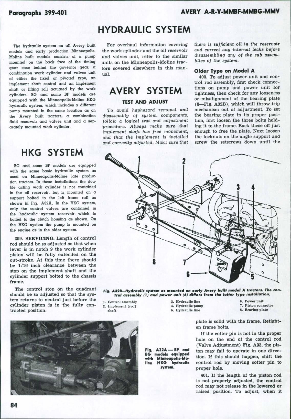
Steering bousing

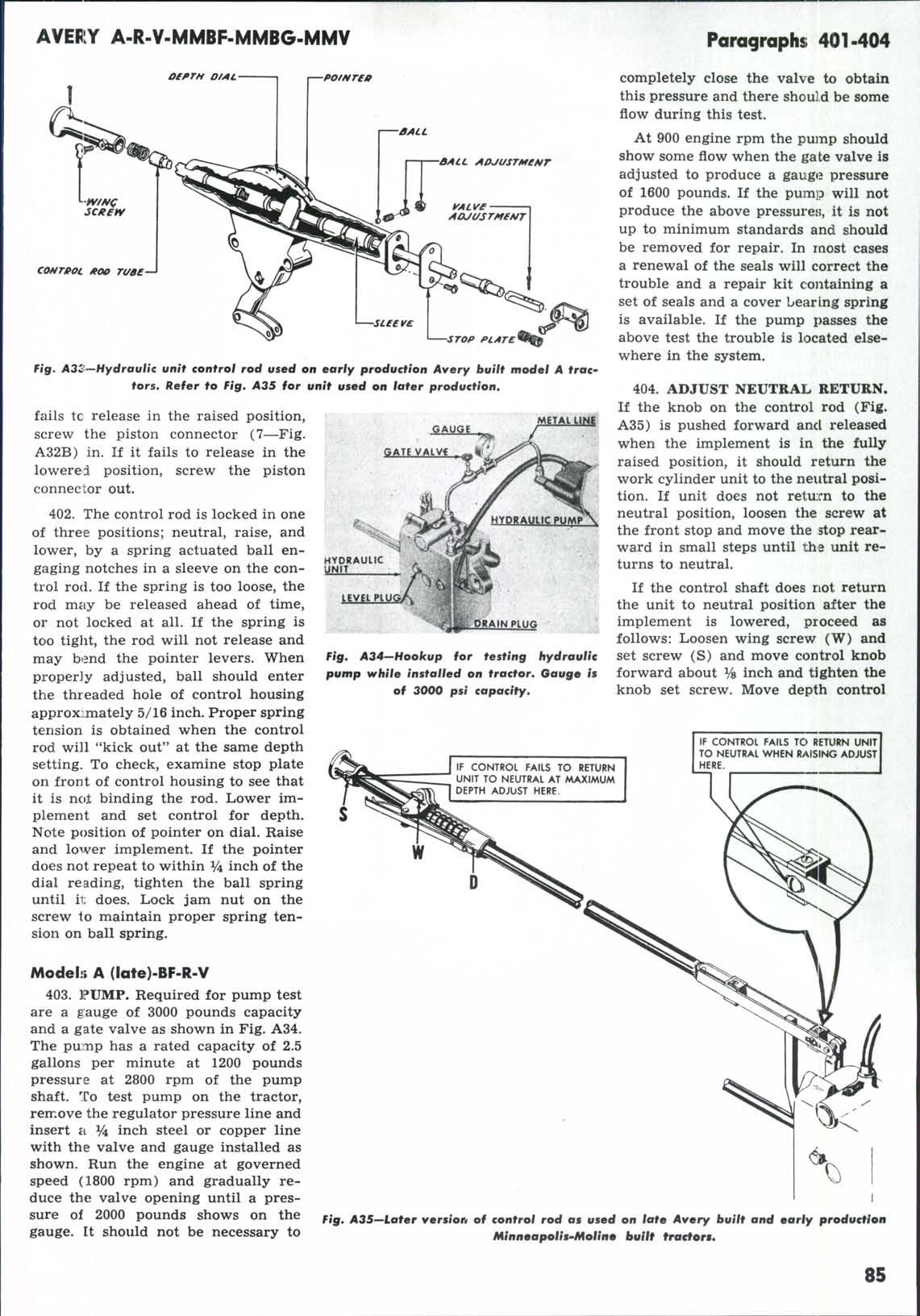
Fig. A41—AII of the seals on the piston rod anti in fhe end cop should be renewed at overhaul.
adjustable but the one under the rear end cap operates only when raising the implement and has a spring which permits the valve to unload at 120-125 psi. The other release valve located under the front end cap operates only when the implement is lowered and has a much ^'heavier" spring which unloads at 1100 psi. Both valves should be removed and inspected for bent or broken springs and condition of valve balls and seats. Care must be exercised when removing the valves to prevent damage to the bores in the case. Renew the small seal ring on each valve seat and do i:he same to the balls if they show signs of not seating properly. Reseat a new ball by a few sharp blows, using a hammer and a brass drift. After resissembling the parts in the order shown, make certain that the small spring in each case is sealed straight in the retainer, the head of which should be flush or slightly within the case uhen fully tightened.
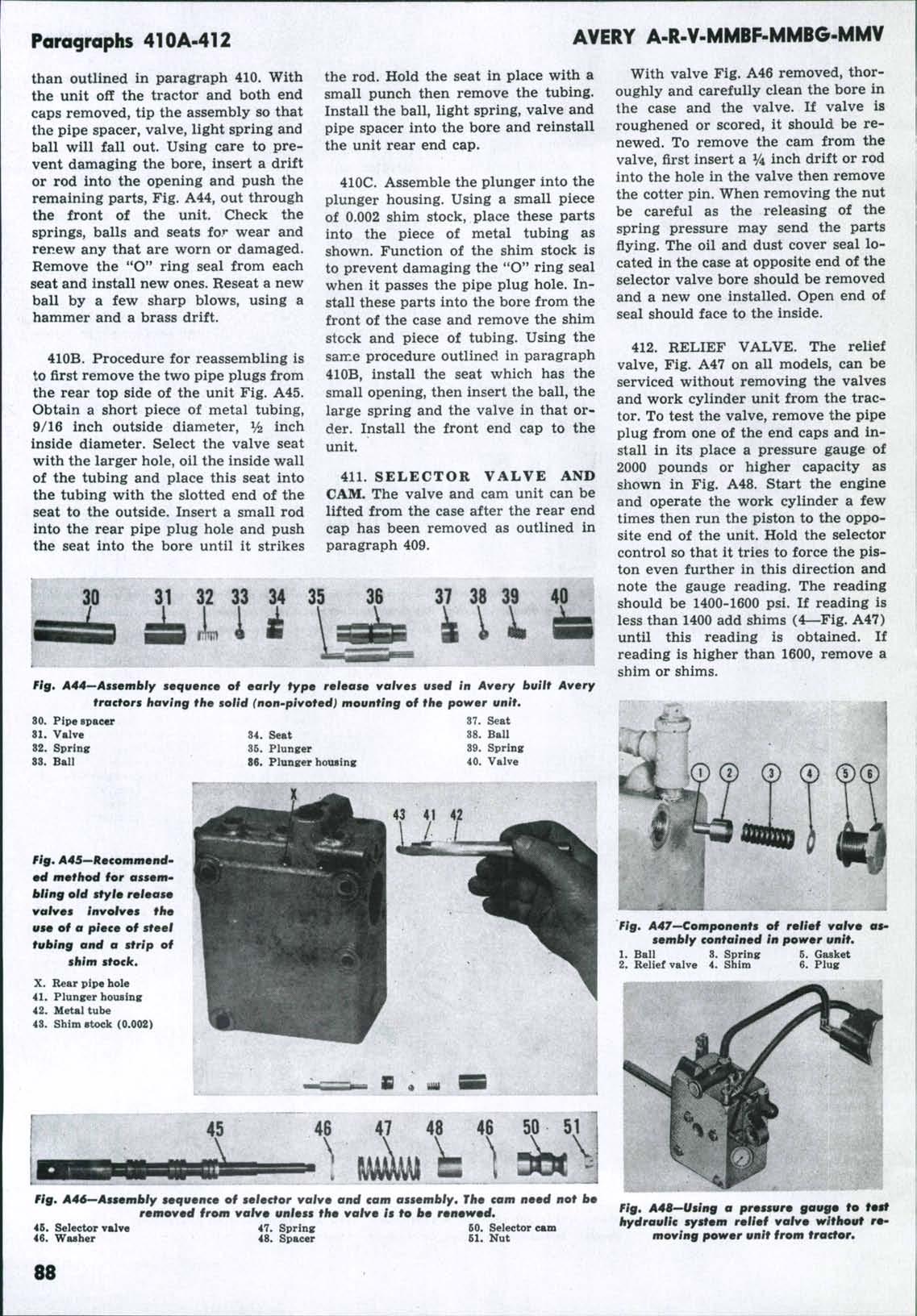
410A. EARLY TYPE RELEASE VALVES. On the older Avery built Avery tractors, the release valves require a different servicing procedure