3 minute read
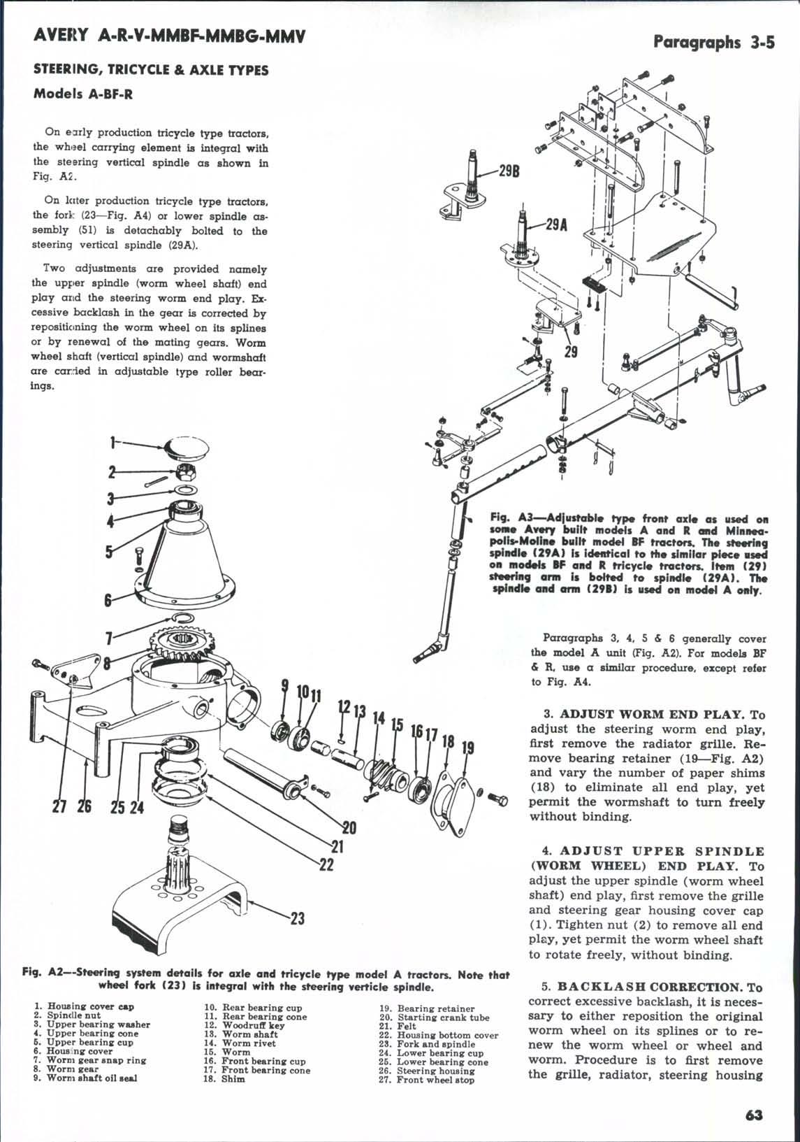
Fork and spindle

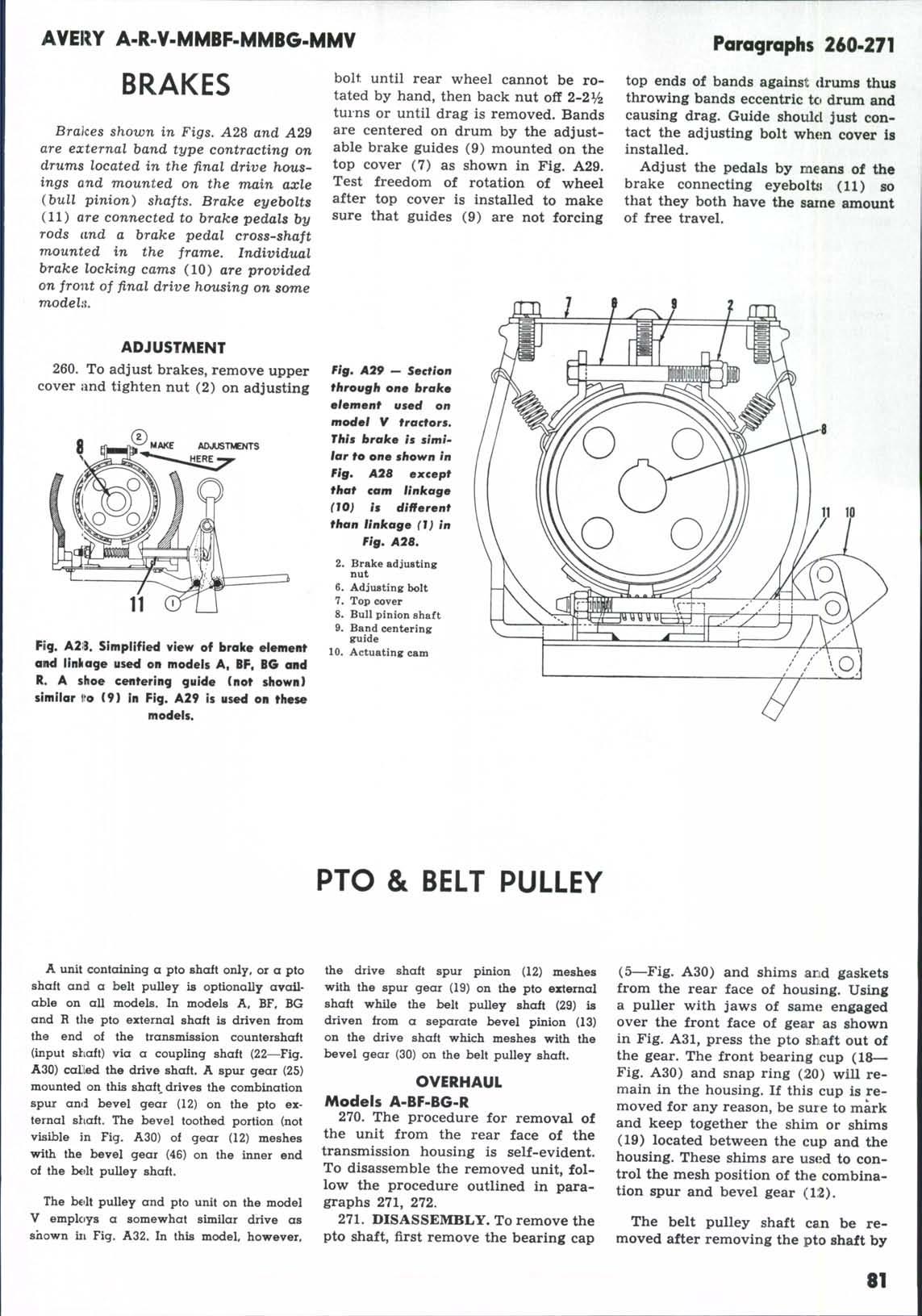
The hydraulic system on all Avery built models and early production MinneapolisMoiine built models consists of a pump mounted on the back face of the timing gear case behind the governor gear, a combination work cylinder and valves unit of either the fixed or pivoted type, an implement shaft control and an implement shaft or lifting roll actuated by the work cylinders. BG and some BF models are equipped with the Minneapolis-Moline HKG hydraulic system, which includes a different pump mounted in the same location as on the Avery built tractors, a combination fluid reservoir and valves unit and a separately mounted work cylinder.
HKG SYSTEM
BG and some BF models are equipped with the same basic hydraulic system as used on Minneapolis-Moline late production tractors. In these installations the double acting work cylinder is not contained in the oil reservoir, but is mounted on a support bolted to the left frame rail as shown in Fig. A32A. In the HKG system, only the control valves are contained in the hydraulic system reservoir which is bolted to the clutch housing as shown. On the HKG system the pump is mounted on the engine as in the older system.
399. SERVICING. Length of control rod should be so adjusted so that when lever is in notch 9 the work cylinder piston will be fully extended on the out-stroke. At this time there should be 1/16 inch clearance between the stop on the implement shaft and the cylinder support bolted to the chassis frame.
The control stop on the quadrant should be so adjusted so that the system returns to neutral just before the cylinder piston is in the fully contracted position.
For overhaul information covering the work cylinder and the oil reservoir and valves unit, refer to the similar units on the Minneapolis-Moline tractors covered elsewhere in this manual.
AVERY SYSTEM
TEST AND ADJUST
To avoid haphazard removal and disassembly of system cornponentSf follow a logical test and adjustment procedure. Always make sure that implement shaft has free movement, and that the implement is installed and correctly adjusted. Mak: sure that there is sufficient oil in the reservoir and correct any internal leaks before disassembling any of the sub assemblies of the system.