8 minute read
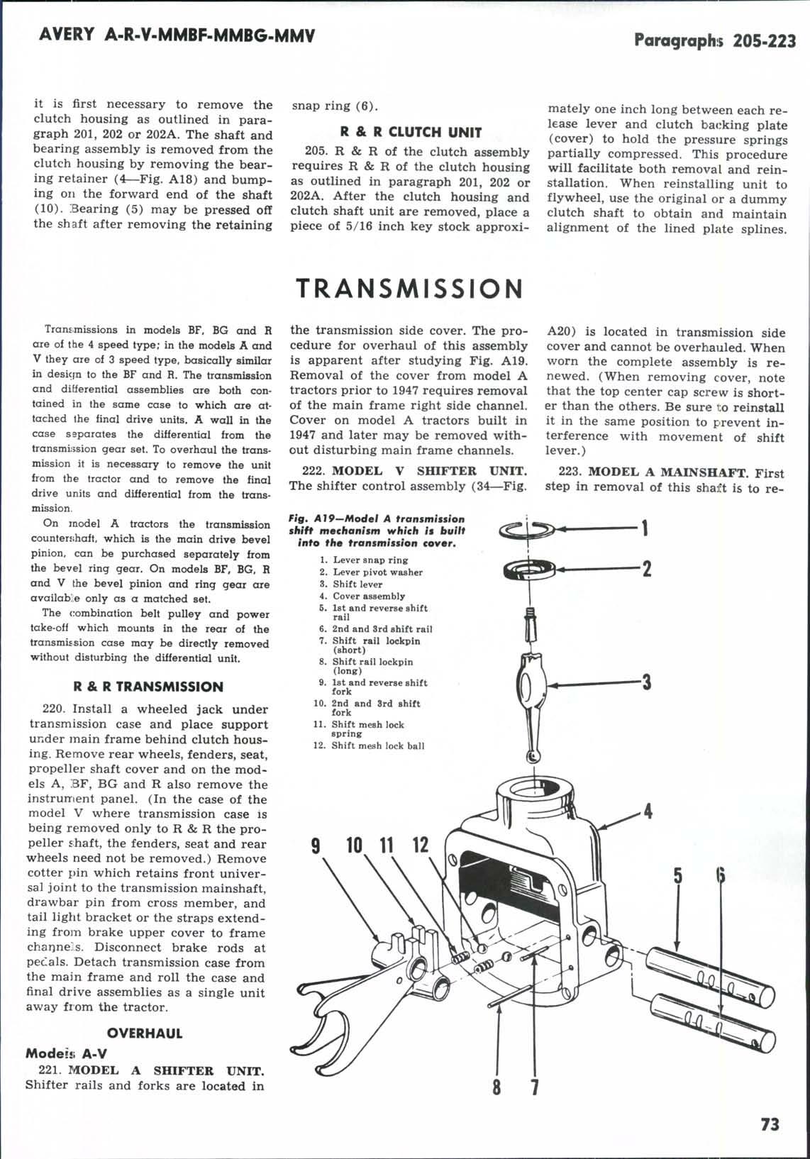
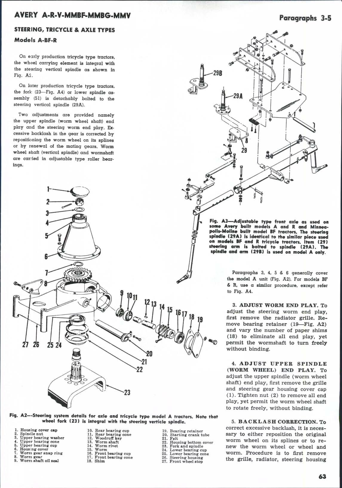
Lower bearing cup

completely close the valve to obtain this pressure and there shoul.d be some flow during this test.
At 900 engine rpm the pump should show some flow when the gate valve is adjusted to produce a gauge pressure of 1600 pounds. If the pum]? will not produce the above pressures, it is not up to minimum standards and should be removed for repair. In most cases a renewal of the seals will correct the trouble and a repair kit containing a set of seals and a cover bearing spring is available. If the pump passes the above test the trouble is located elsewhere in the system.
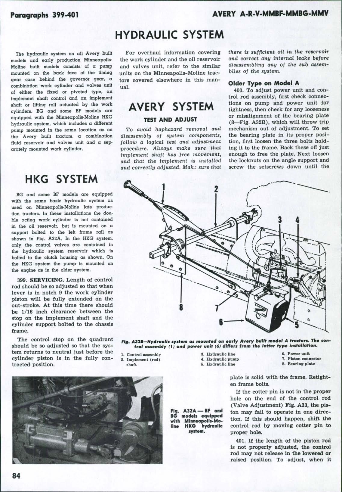
Fig* A3<t—Hydraulic unit control rod used on early production Avery built model A trac tors. Refer to Fig, A35 for unit used on later production, 404. ADJUST NEUTRAL RETURN.
fails tc release in the raised position, screw the piston connector (7—Fig. A32B) in. If it fails to release in the lowered position, screw the piston connector out. If the knob on the control rod (Fig. A35) is pushed forward ancL released when the implement is in the fully raised position, it should return the work cylinder unit to the neutral position. If unit does not return to the 402. The control rod is locked in one neutral position, loosen the screw at of three positions; neutral, raise, and the front stop and move the stop rearlower, by a spring actuated ball enward in small steps until the unit regaging notches in a sleeve on the conturns to neutral. trol rod. If the spring is too loose, the If the control shaft does not return rod may be released ahead of time, the unit to neutral position after the or not locked at all. If the spring is implement is lowered, proceed as too tight, the rod will not release and follows: Loosen wing screw (W) and may bend the pointer levers. When Fig, A34—Hookup for testing hydraulic set screw (S) and move control knob properly adjusted, ball should enter pump while installed on tractor. Gauge is forward about Vs inch and tighten the the threaded hole of control housing of 3000 psi capacity. knob set screw. Move depth control approx:.mately 5/16 inch. Proper spring tension is obtained when the control rod will "kick out" at the same depth setting. To check, examine stop plate on front of control housing to see that IF CONTROL FAILS TO RETURN UNIT TO NEUTRAL AT MAXIMUM it is nc»± binding the rod. Lower imDEPTH ADJUST HERE. plement and set control for depth. Note position of pointer on dial. Raise and lower implement. If the pointer does not repeat to within ^ inch of the W dial reading, tighten the ball spring until ii; does. Lock jam nut on the screw lo maintain proper spring tension on ball spring.
Modelii A (late)-BF-R-V
403. ]?UMP. Required for pump test are a gauge of 3000 pounds capacity and a gate valve as shown in Fig. A34. The pump has a rated capacity of 2.5 gallons per minute at 1200 pounds pressure at 2800 rpm of the pump shaft. To test pump on the tractor, remove the regulator pressure line and insert «i V4 inch steel or copper line with the valve and gauge installed as shown. Run the engine at governed speed (1800 rpm) and gradually reduce the valve opening until a pressure of 2000 pounds shows on the gauge. It should not be necessary to
(D) to the rear as far as possible then tighten the wing screw. If after once repeating this adjustment, the unit does not return to neutral, the control should be checked and reset as outlined in paragraph 405.
405. RESETTING THE CONTROL ROD UNIT. When the minor adjustment of the control rod outlined in paragraph 404 does not correct the failure of the unit to return to neutral, it should be given a major adjustment as follows:
405A. Remove the set screw from the control knob and withdraw the knob and rod unit. If the distance from the nearest face of the knob and the end of the rod is other than 7^5/16 inches as shown in Fig. A36, loosen the rod lock nut and turn the knob on the rod threads until this distance is obtained.
Measure the distance from the depth control rod pin to the farthest face of the rear control stop. If this distance is other than 28 Vs inches on models A, BF and R or 14^4 inches on the model V, the rod must be reset. This usually can be done without completely disassembling the control by first determining the amount that the rod must be shortened or lengthened. Using a long screwdriver, loosen the set screw (O) and remove the pin and the front stop. Allow the depth control rod to move forward until hole in rod aligns with hole in control tube. Insert the previously removed pin through tube and rod. After loosening lock nut, rotate the rear stop the required amount to obtain the 28^ or 14 Ys dimension. If adjustment cannot be obtained in this manner it will be necessary to remove the stop from the rod and withdraw same through rear end of tube. Reassemble the stop to the rod, adjust to correct length, mark the position of stop on rod, then disassemble and reinstall to the marked position.
RESEALING THE PUMP
Pumps used on models A, BF and R are the same Pesco pumps which dif^ fer only in detail from, the unit used on the model V. The tractor manufacturer does not catalog a full line of parts used internally in the pumps. Available are the necessary coupling, attaching parts and a repair kit containing a complete set of seals and a cover hearing spring.
406. After removing unit from tractor, cork the openings and thoroughly wash the pump in a suitable cleaning fluid. Remove the drive coupling and the cap screws securing the cover to the body. Loosen the cover by tapping it carefully with a plastic hammer then slide the cover off the drive gear shaft. Wash the cover assembly in cleaning fiuid. Renew all of the seal rings, shims and the cover bearing spinrg.
If the cover bearings are grooved or otherwise worn, it will be necessary to obtain an exchange pump or a new pump as M-M does not catalog the cover bearings or gears. On model V tractors the shaft oil seal in the pump cover is a metallic cartridge type and should be renewed at this time. The shaft oil seal in the cover of the pumps for models A, BF and R is an **O" ring which should be renewed. Be sure that the small drain holes in the cover are not plugged.
Thoroughly wash the pump body assembly in a suitable cleaning fluid. Carefully remove the gears from the body. Mark the body bearings as to relative location then remove them from the body. If gears are chipped or worn or if body bearings are grooved or otherwise worn, obtain a new or exchange pump as gears and bearings are not catalogued by M-M. Make sure that all parts are spotlessly clean then install a new oil seal ring. Oil all parts installed in the body then assemble the body to the cover. Tighten the
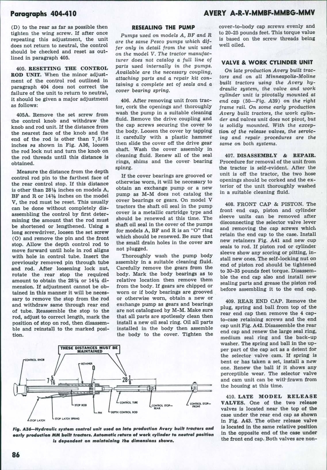
THESE DISTANCES MUST BE MAINTAINED
cover-to-body cap screws evenly and to 20-25 pounds feet. This torque value is based on the screw threads being well oiled.
VALVE & WORK CYLINDER UNIT
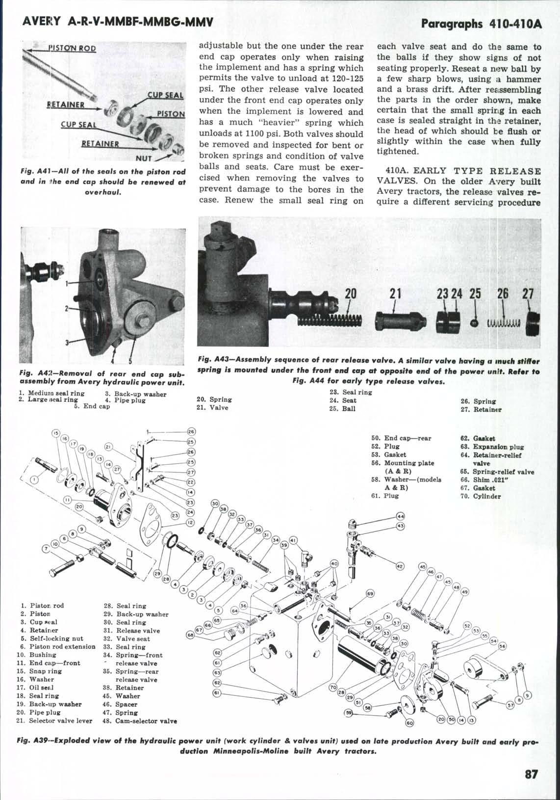
On late produxition Avery built tractors and on all Minneapolis-Moline built tractors using the Avery hydraulic system, the valve and work cylinder unit is pivotally m^ounted at end cap (50—Fig. A39) on the right frame rail. On some early production Avery built tractors, the work cylinder and valves unit does not pivot, but is solidly mounted. With the exception of the release valves, the servicing and repair procedures are the same on both systems.
407. DISASSEMBLY & REPAIR. Procedure for removal of the unit from the tractor is self-evident. After the unit is off the tractor, the two hose openings should be corked and the exterior of the unit thoroughly washed in a suitable cleaning fluid.
408. FRONT CAP & PISTON. The front end cap, piston and cylinder sleeve units can be removed after disconnecting the selector valve lever and removing the cap screws which retain the end cap to the case. Install new retainers Fig. A41 and new cup seals to rod. If piston rod or cylinder sleeve show any scoring or pitting, install new ones. The self-locking nut on end of piston rod should be tightened to 30-35 pounds feet torque. Disassemble the end cap also and install new sealing parts and grease the piston rod before assembling it to the end cap.
409. REAR END CAP. Remove the plug, spring and ball from top of the rear end cap then remove the 4 capto-case retaining screws and the end cap unit Fig. A42. Disassemble the rear end cap and renew the large seal ring, medium seal ring and the back-up washer. The spring and ball in the upper part of the cap act as a detent for the selector valve cam. If spring is bent or has taken a set, install a new one. Renew the ball if it shows any perceptible wear. The selector valve and cam unit can be withdrawn from the housing at this time.
410. LATE MODEL RELEASE CONTROL STOr— VALVES. One of the two release ntONT valves is located near the top of the case under the rear end cap as shown in Fig. A43. The other release valve riff. A3d—HydrouKc ByMfmm control unif vfd on iafm production Avry Itviif troctors oncf oarly production MM buiif fraefors. Automatic rmfurn of work tyiindor to nmufrai position it dopmndmnf on malnfaining thm dimmngiont shown. is located in the same relative position in the opposite end of the case under the front end cap. Both valves are non