www.classicmachinery.net
AVERY A-R-Y-MMBF-MMBG-MMY
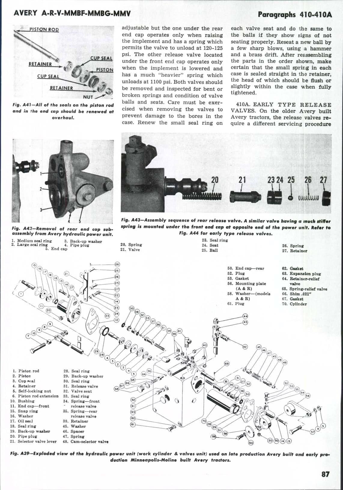
Paragraphs 401-404 completely close the valve to obtain this pressure and there shoul.d be some flow during this test. At 900 engine rpm the pump should show some flow when the gate valve is adjusted to produce a gauge pressure of 1600 pounds. If the pum]? will not produce the above pressures, it is not up to minimum standards and should be removed for repair. In most cases a renewal of the seals will correct the trouble and a repair kit containing a set of seals and a cover bearing spring is available. If the pump passes the above test the trouble is located elsewhere in the system.
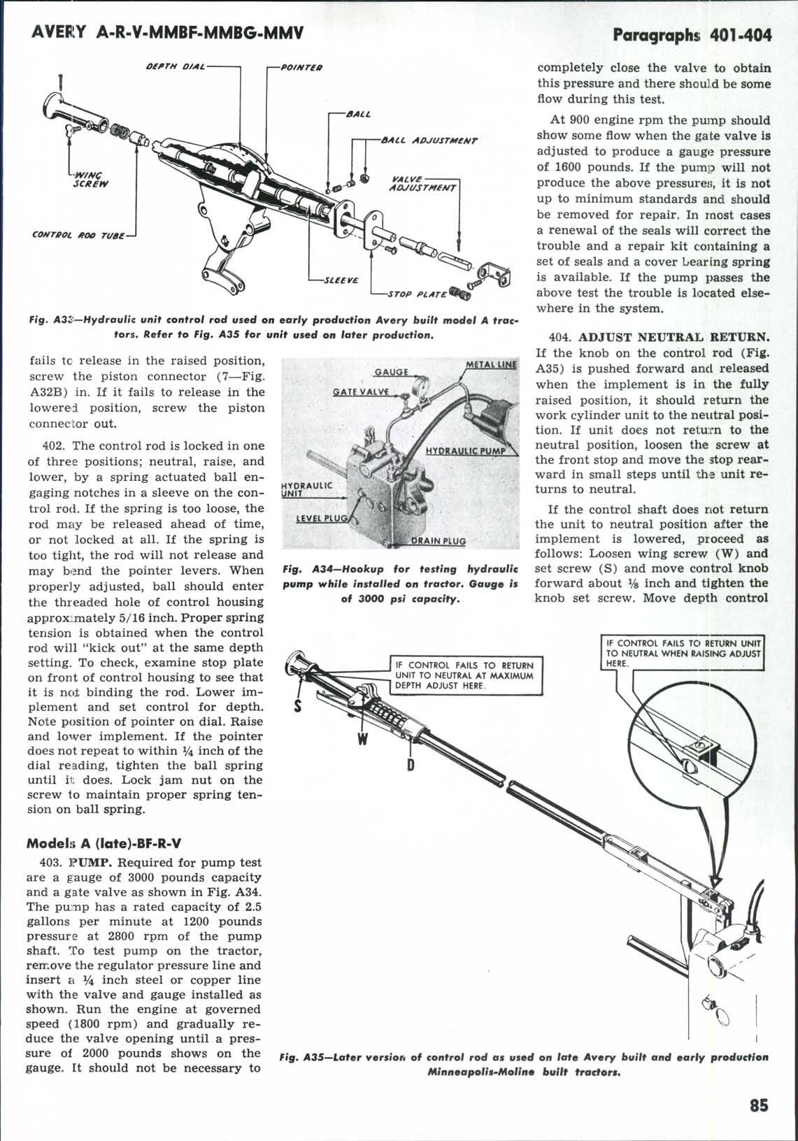
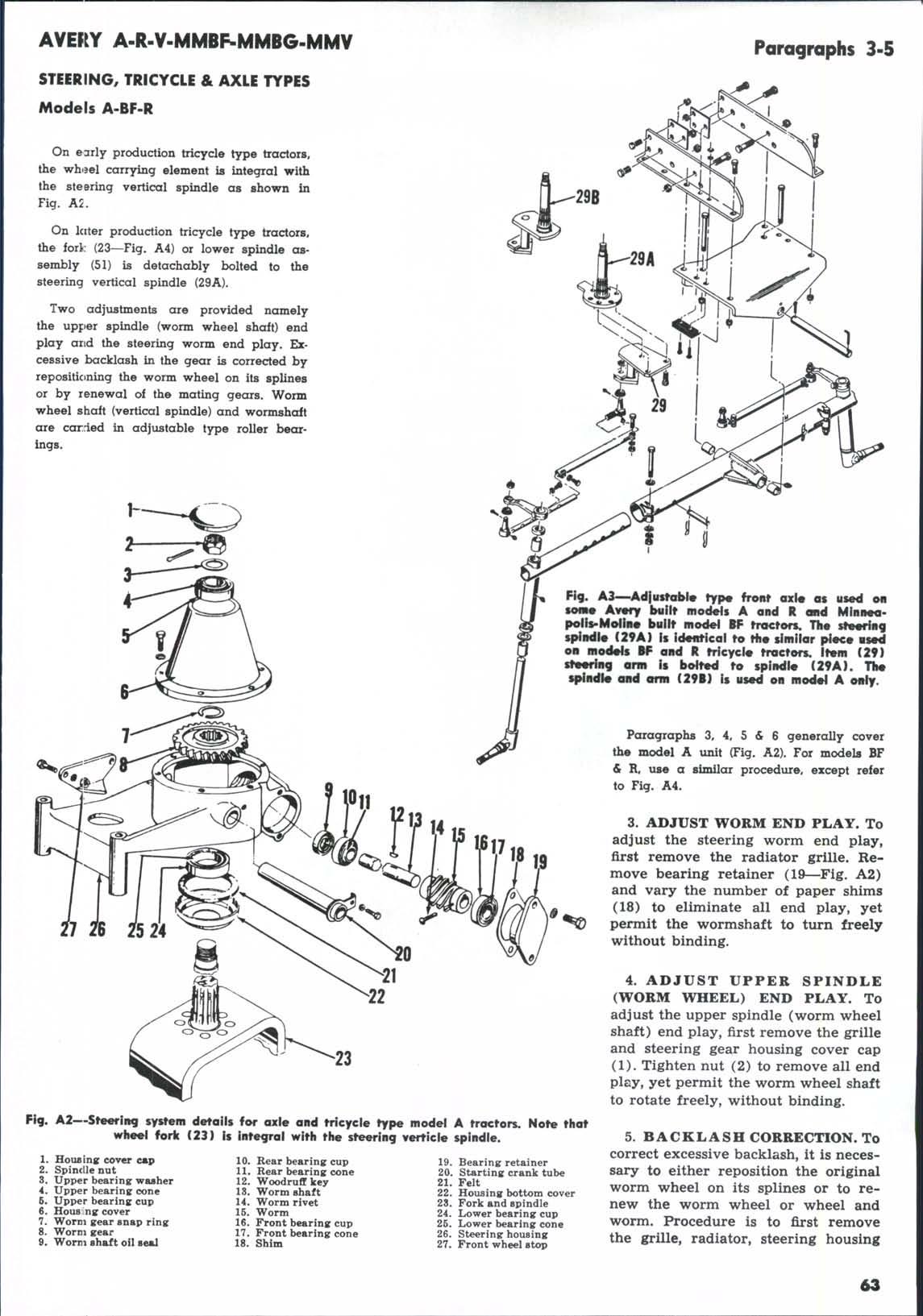
Fig* A3<t—Hydraulic unit control rod used on early production Avery built model A trac tors. Refer to Fig, A35 for unit used on later production,
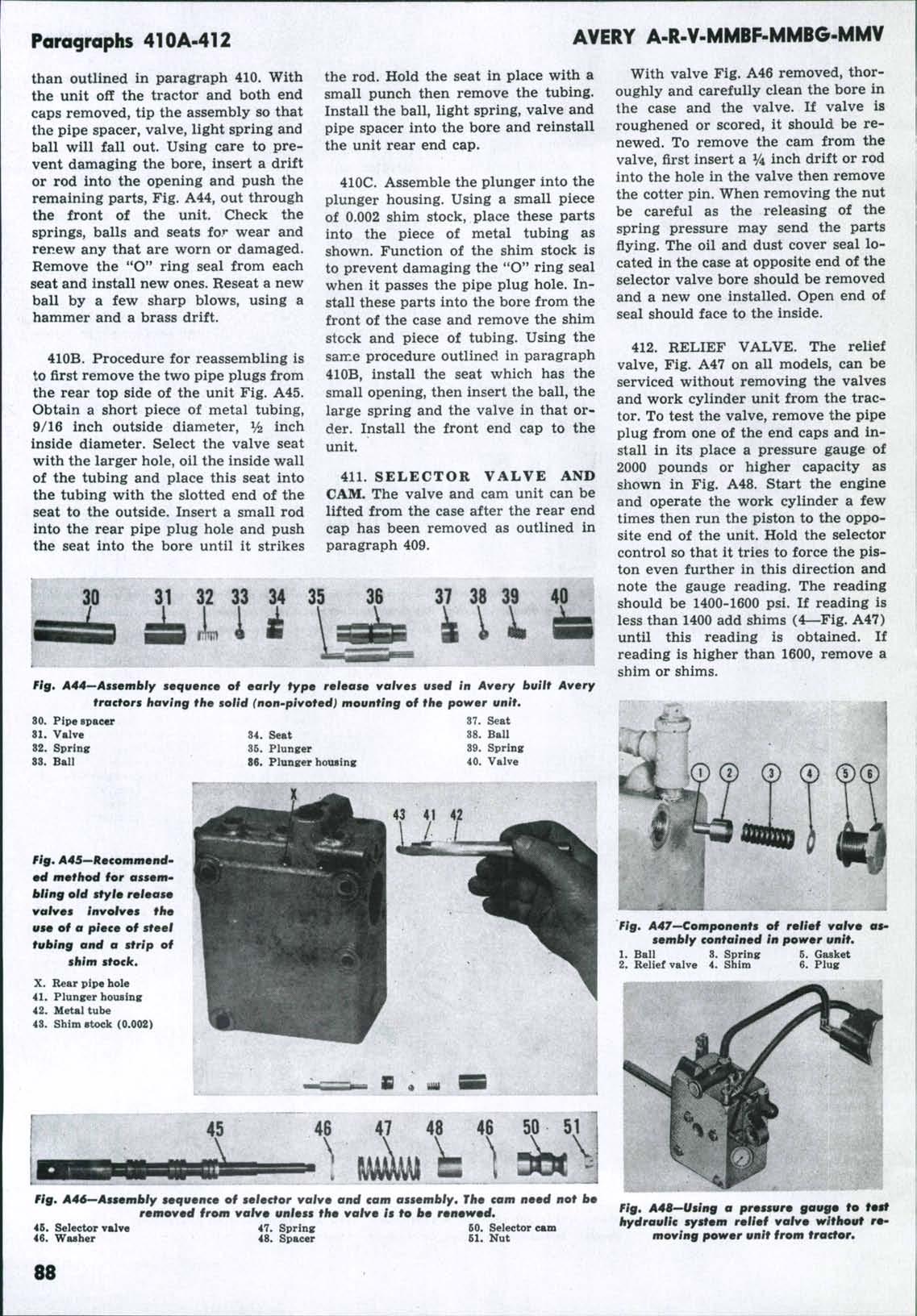
fails tc release in the raised position, screw the piston connector (7—Fig. A32B) in. If it fails to release in the lowered position, screw the piston connector out. 402. The control rod is locked in one of three positions; neutral, raise, and lower, by a spring actuated ball engaging notches in a sleeve on the control rod. If the spring is too loose, the rod may be released ahead of time, or not locked at all. If the spring is too tight, the rod will not release and may bend the pointer levers. When properly adjusted, ball should enter the threaded hole of control housing approx:.mately 5/16 inch. Proper spring tension is obtained when the control rod will "kick out" at the same depth setting. To check, examine stop plate on front of control housing to see that it is nc»± binding the rod. Lower implement and set control for depth. Note position of pointer on dial. Raise and lower implement. If the pointer does not repeat to within ^ inch of the dial reading, tighten the ball spring until ii; does. Lock jam nut on the screw lo maintain proper spring tension on ball spring. Modelii A (late)-BF-R-V 403. ]?UMP. Required for pump test are a gauge of 3000 pounds capacity and a gate valve as shown in Fig. A34. The pump has a rated capacity of 2.5 gallons per minute at 1200 pounds pressure at 2800 rpm of the pump shaft. To test pump on the tractor, remove the regulator pressure line and insert «i V4 inch steel or copper line with the valve and gauge installed as shown. Run the engine at governed speed (1800 rpm) and gradually reduce the valve opening until a pressure of 2000 pounds shows on the gauge. It should not be necessary to
Fig, A34—Hookup for testing hydraulic pump while installed on tractor. Gauge is of 3000 psi capacity.
404. ADJUST NEUTRAL RETURN. If the knob on the control rod (Fig. A35) is pushed forward ancL released when the implement is in the fully raised position, it should return the work cylinder unit to the neutral position. If unit does not return to the neutral position, loosen the screw at the front stop and move the stop rearward in small steps until the unit returns to neutral. If the control shaft does not return the unit to neutral position after the implement is lowered, proceed as follows: Loosen wing screw (W) and set screw (S) and move control knob forward about Vs inch and tighten the knob set screw. Move depth control
IF CONTROL FAILS TO RETURN UNIT TO NEUTRAL AT MAXIMUM DEPTH ADJUST HERE.
W
Fig. A35~-Later versioifa of control rod as used on late Avery built and early production MinneapoliS'Moline built fracfor».
85