www.classicmachinery.net
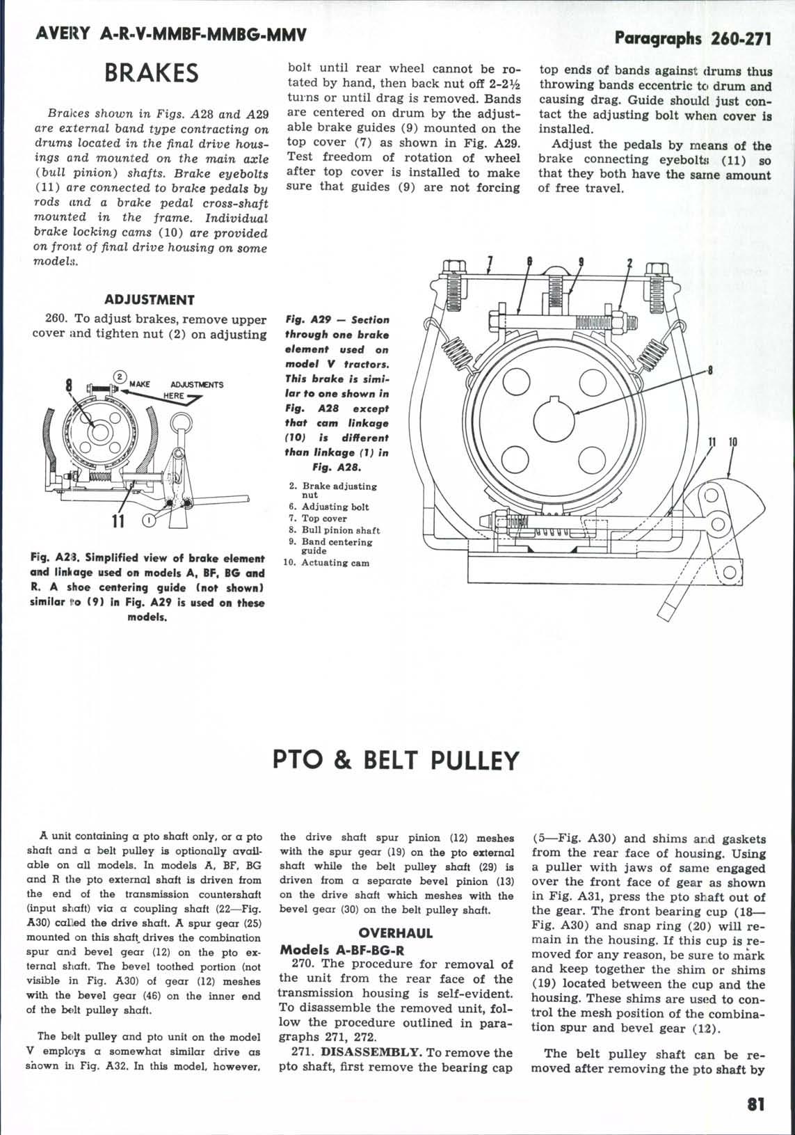
AVERY A-R-Y-MMBF-MMBG-MMY bolt until rear wheel cannot be rotated by hand, then back nut off 2-2 V2 turns or until drag is removed. Bands are centered on drum by the adjustable brake guides (9) mounted on the top cover (7) as shown in Fig. A29. Test freedom of rotation of wheel after top cover is installed to make sure that guides (9) are not forcing
BRAKES Brakes shown in Figs. A28 and A29 are external hand type contracting on drums located in the final drive housings and mounted on the main axle (bull pinion) shafts. Brake eyebolts (11) are connected to brake pedals by rods and a brake pedal cross-shaft mounted in the frame. Individual brake locking cams (10) are provided on front of final drive housing on some TTiodehi, ADJUSTMENT 260. To adjust brakes, remove upper cover and tighten nut (2) on adjusting
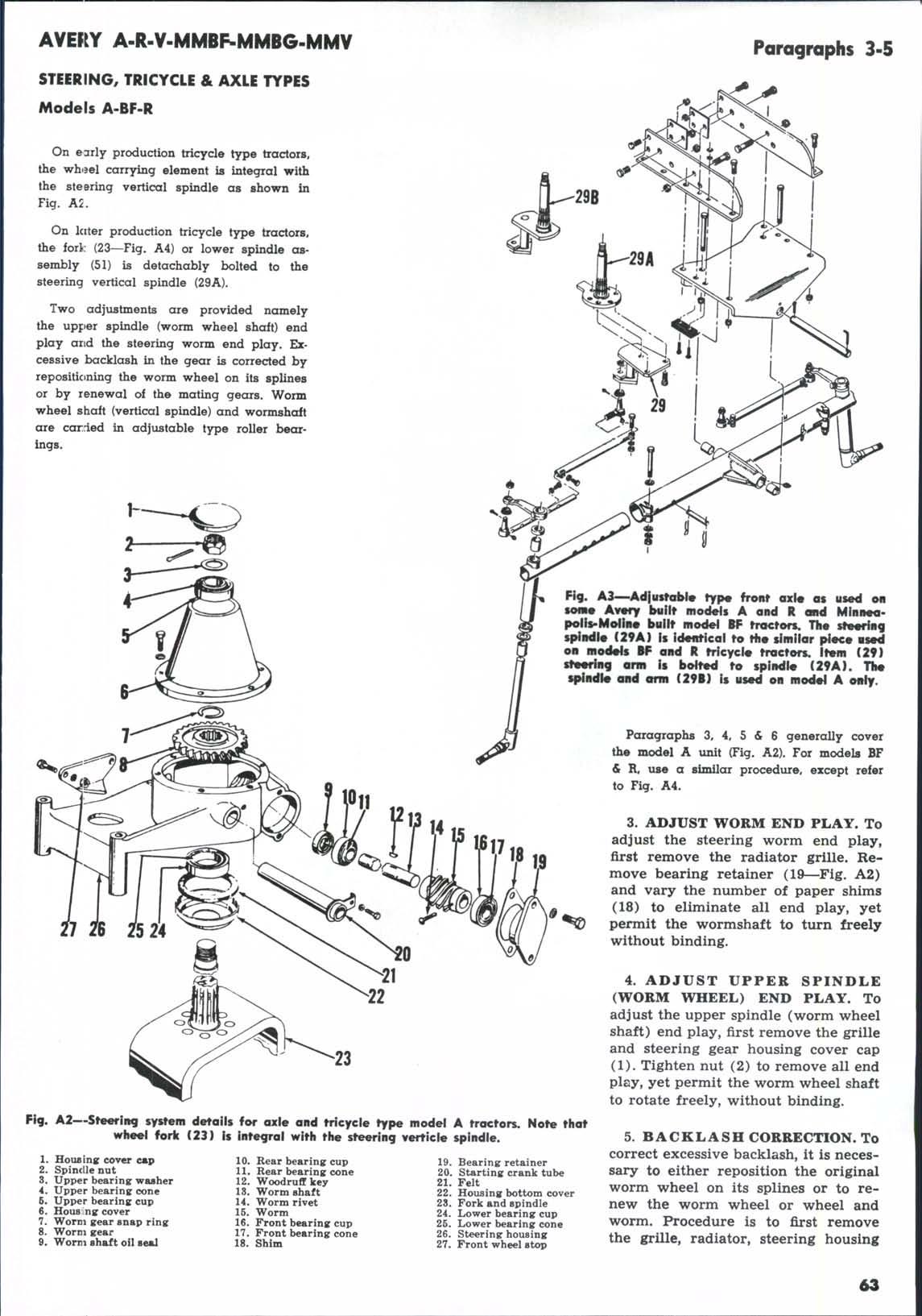
Paragraphs 260-271 top ends of bands against drums thus throwing bands eccentric tci drum and causing drag. Guide should just contact the adjusting bolt when cover is installed. Adjust the pedals by means of the brake connecting eyebolts (11) so that they both have the same amount of free travel.
Fig. A29 - Section ffcrougfi one brakm 0l9m9nf used on model V tractors. This brake is simiiar to one shown in fig. A28 except that cam linkage (10) is different than linkage (1) in Pig. A2B,
AOJUSTMENTS ERE-
2. Brake adjuating nut AdjustinK bolt Top cover Bull pinion shaft Band centering: guide 10. Actuating cam 6. 7. 8. 9.
Fig. A23. Simplified view of brake element ond linliage used on models A, BF, BG ond R. A shoe centering guide (not shown) similor l^o (9) In Fig. A29 is used on these models.
PTO & BELT PULLEY A unit contaimng a pto shait only, or a pto the drive shaft spur pinion (12) meshes shaft and a belt pulley is optionally avaUwith the spur gear (19) on the pto external able on all models. In models A, BF, BG shaft whUe the belt pulley shaft (29) is and R the pto external shaft is driven from driven from a separate bevel pinion (13) the end of the transmission countershaft on the drive shaft which meshes with the (input shaft) via a coupling shaft (22—Fig. bevel gear (30) on the belt pulley shaft. A30) called the drive shaft. A spur gear (25) OVERHAUL mounted on this shaft, drives the combination Models A-BF-BG-R spur anii bevel gear (12) on the pto external shaft. The bevel toothed portion (not 270. The procedure for removEil of visible in Fig. A30) of gear (12) meshes the unit from the rear face of the with the bevel gear (46) on the inner end transmission housing is self-evident. of the bctlt pulley shaft. To disassemble the removed unit, folThe bolt pulley and pto unit on the model V employs a somewhat similar drive as shown ill Fig. A32. In this model, however.
low the procedure outlined in paragraphs 271, 272. 271. DISASSEMBLY. To remove the pto shaft, first remove the bearing cap
(5—Fig. A30) and shims and gaskets from the rear face of housing. Using a puller with jaws of same engaged over the front face of gear as shown in Fig. A31, press the pto shiaft out of the gear. The front bearing cup (18— Fig. A30) and snap ring (20) wiU remain in the housing. If this cup is removed for any reason, be sure to mark and keep together the shim or shims (19) located between the cup and the housing. These shims are used to control the mesh position of the combination spur and bevel gear (12). The belt pulley shaft can be removed after removing the pto shaft by
81