www.classicmachinery.net
AVERY A-R-V-MMBF-MMBG-MMV
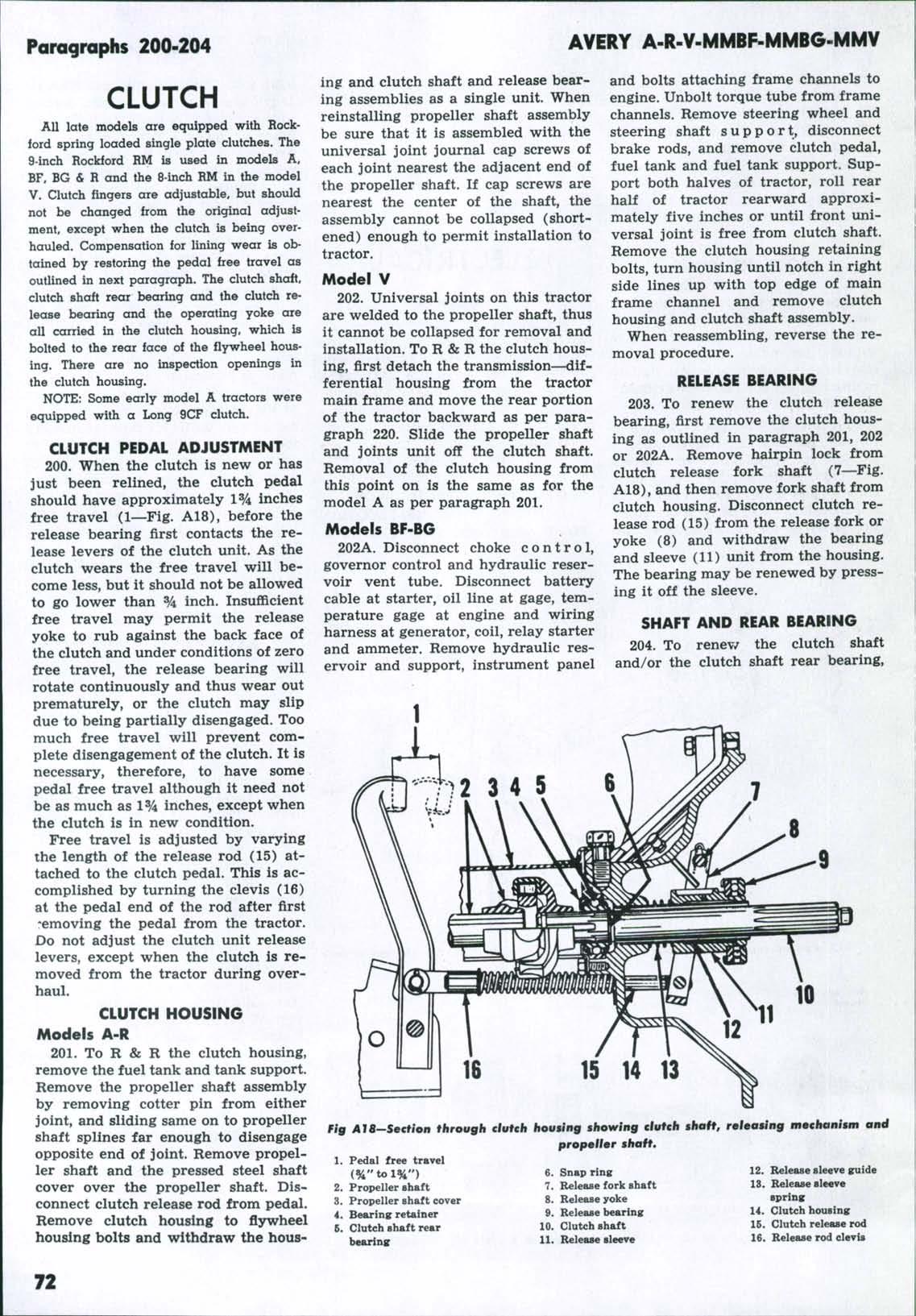
it is first necessary to remove the clutch housing as outlined in paragraph 201, 202 or 202A. The shaft and bearing assembly is removed from the clutch housing by removing the bearing retainer (4—Fig. A18) and bumping on the forward end of the shaft (10). Bearing (5) may be pressed off the shaft after removing the retaining
ParagraphiS 205-223
snap ring (6). R & R CLUTCH UNIT
205. R & R of the clutch assembly requires R & R of the clutch housing as outlined in paragraph 201, 202 or 202A. After the clutch housing and clutch shaft unit are removed, place a piece of 5/16 inch key stock approxi-
mately one inch long between each release lever and clutch backing plate (cover) to hold the pressure springs partially compressed. This procedure will facilitate both removal and reinstallation. When reinstalling unit to flywheel, use the original or a dummy clutch shaft to obtain and maintain alignment of the lined plate splines.
TRANSMISSION Transmissions in models BF, BG and R ore oi the 4 speed type; in the models A and V they are oi 3 speed type, basically similar in design to the BF and R. The transmission and differential assemblies are both contained in the same case to which are attached the final drive units. A wall in the case separates the differential from the transmission gear set. To overhaul the transmission it is necessary to remove the unit from the tractor and to remove the final drive units and differential from the transmission. On raodel A tractors the transmission countenihaft. which is the main drive bevel pinion, can be purchased separately from the bevel ring gear. On models BF, BG, R and V the bevel pinion and ring gear are avallabie only as a matched set. The combination belt pulley and power take-off which mounts in the rear of the transmission case may be directly removed without disturbing the differential unit.
R & R TRANSMISSION
220. Install a wheeled jack under transmission case and place support under main frame behind clutch housing. Remove rear wheels, fenders, seat, propeller shaft cover and on the mod* els A, BF, BG and R also remove the instrument panel. (In the case of the model V where transmission case is being removed only to R & R the propeller shaft, the fenders, seat and rear wheels need not be removed.) Remove cotter pin which retains front universal joint to the transmission mainshaft, drawbar pin from cross member, and tail light bracket or the straps extending from brake upper cover to frame channels. Disconnect brake rods at pecals. Detach transmission case from the main frame and roll the case and final drive assemblies as a single unit away from the tractor.
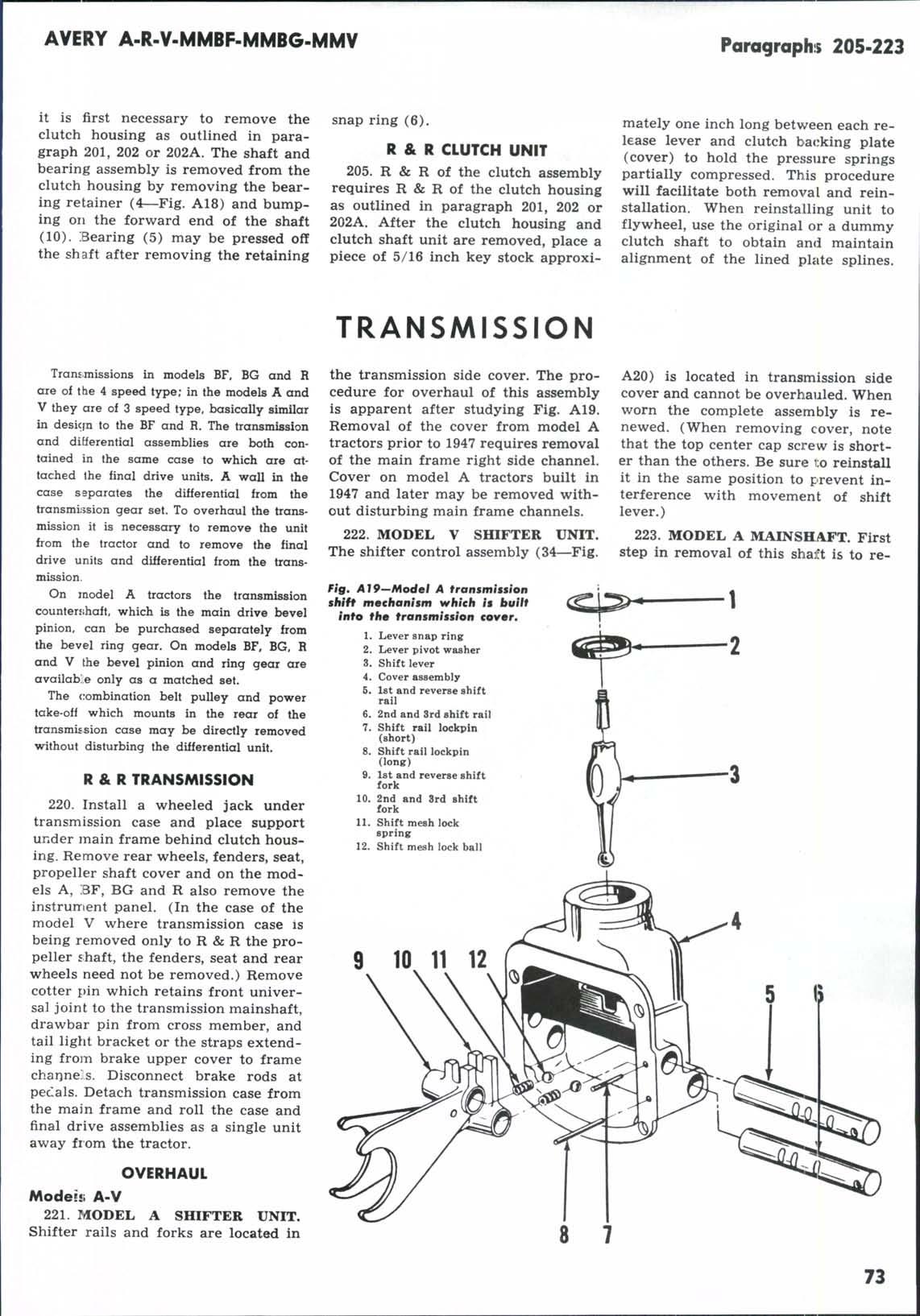
the transmission side cover. The procedure for overhaul of this assembly is apparent after studying Fig. A19. Removal of the cover from model A tractors prior to 1947 requires removal of the main frame right side channel. Cover on model A tractors built in 1947 and later may be removed without disturbing main frame channels. 222. MODEL V SHIFTER
UNIT.
A20) is located in transmission side cover and cannot be overhauled. When worn the complete assembly is renewed. (When removing cover, note that the top center cap screw is shorter than the others. Be sure to reinstall it in the same position to prevent interference with movement of shift lever.) 223. MODEL A MAINSHAFT. First step in removal of this shaft is to re-
The shifter control assembly (34—Fig. Fig, Al9—Model A tronsmissfon shift mechanism which is built into the transmission cover, 1. Lever snap ring 2. Lever pivot washer 3. Shift lever 4. Cover assembly 5. 1st and reverse shift rail 6. 2nd and 3rd shift rail 7. Shift rail lockpin (short) 8. Shift rail lockpin (long) 9. 1st and reverse shift fork 10. 2nd and 3rd shift fork 11. Shift mesh lock spring 12. Shift mesh lock ball
OVERHAUL Mode!!i A-V 221. T4ODEL A
SHIFTER
UNIT.
Shifter rails and forks are located in
8
7 73