www.classicmachinery.net
AVERY A-R-V-MMBF-MMBG-MMY CRANKSHAFT OIL SEALS 47. Front oil seal (4—-Fig. A8) is located in oil pan and timing gear cover. Refer to paragraph 29 for removal procedure. 48. Rear oil seal assembly is installed in bell housing (flywheel housing) and contacts a flange on front face of flywheel. Renewal of seal requires removal of clutch and flywheel. When installing seal in bell housing (Fig. AlO) be sure seal is concentric with flywheel flange and flywheel flange is true and smooth.
OIL PUMP 49. Oil pump is located in oil pan and driven by helical gear from the center of the camshaft. To remove oil pump, remove oil pan and cap screws retaining oil pump to cylinder block. On mcdel V tractors remove also the oil line connecting oil pump to engine oil passage. (On models A, BF, BG & R tractor engines, oil is discharged from pump directly to main oil passage through pump body and flange gasket.) To disassemble pump,remove screws retaini]ig cover to pump housing and remove; cover and idler gear and shaft assembly. Drive riveted pin out of driving gear and remove gear and thrust washer. Oil pump body drive gear ar d shaft unit can be withdrawn from E"ump housing. To remove oil pump body drive gear and idler gear from tlieir shafts, press gears farther onto sh afts to expose snap ring in shaft groove. Remove snap rings and press gears from shafts. Reassembly is reverse of disassembly. Backlash between oil pump body gears is 0.0080.010 inch and drive shaft end play 0.0015-0.003 inch. Gear cover plate is a lapped flt on the pump housing and no gasket is required. Cover retaining cap scrtjws should be locked by cen-
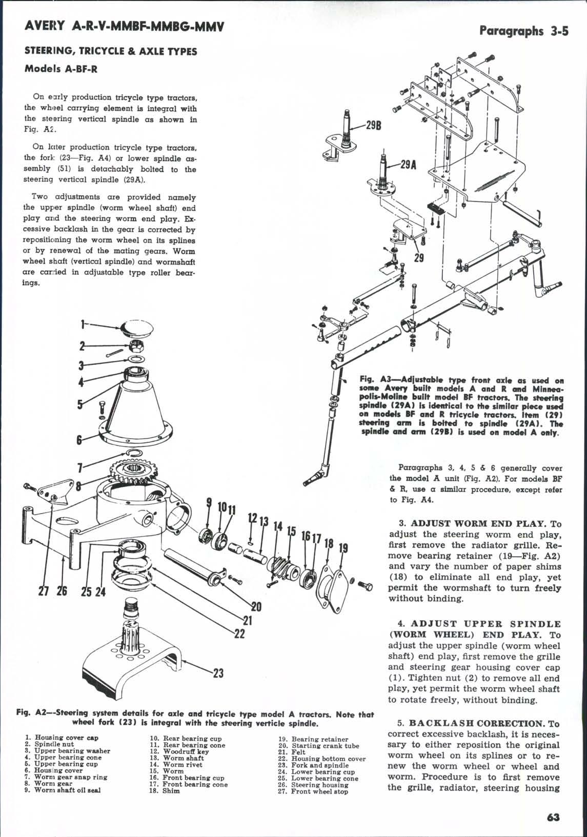
Poragraphs 47-69
ter-punching cover into slots. NOTE: Oil pump from IXA3 or IXK3 engines cannot be used on IXB3 engine as body of pump will not clear main bearing cap screw. PRESSURE RELIEF VALVE 50. Oil pressure relief valve (3— Fig. A8) is located externally on left side of engine just to the rear of the timing gear cover. Remove cover, loosen locknut and turn adjusting screw to adjust oil pressure. Oil pressure should be 15 pounds at 1000 rpm, with engine and oil completely warmed.
OIL FILTER 51. This unit is of the partial flow, replaceable element type. Cartridge type element may be renewed after flrst removing tractor hood, NOTE: Some model A tractors were equipped with the Michiana screw base type filter and removal of hood for renewal of cartridge is not necessary on these models.
CARBURETOR 60. Model A tractors are equipped with model YC2A, YC2B or YCIOA Tillotson carburetor; model V tractors with Tillotson YC6A; models BF, BG & R with Marvel-Schebler TSX400. Adjustment procedures are conventional. Float setting is 1 5/64 inches for Tillotson, ^ inch for MarvelSchebler.
GOVERNOR ADJUST
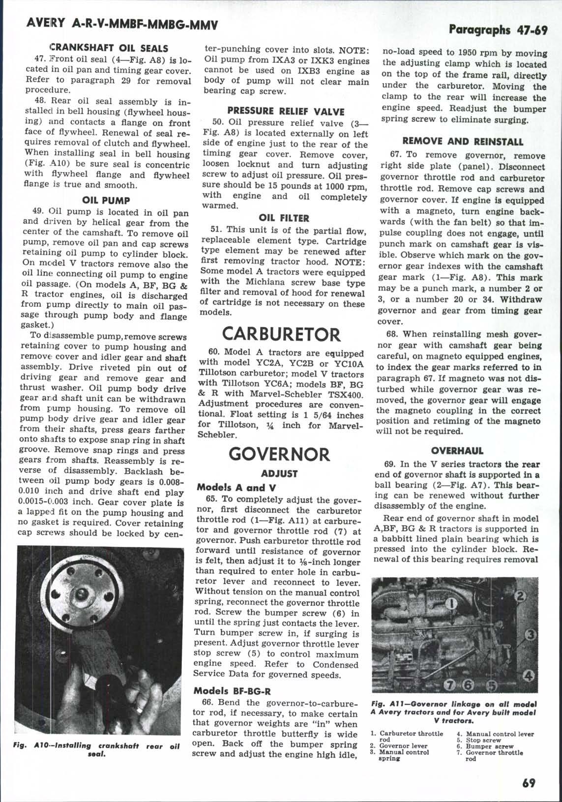
Models A and V 65. To completely adjust the governor, flrst disconnect the carburetor throttle rod (1—Fig. A l l ) at carburetor and governor throttle rod (7) at governor. Push carburetor throttle rod forward until resistance of governor is felt, then adjust it to %-inch longer than required to enter hole in carburetor lever and reconnect to lever. Without tension on the manual control spring, reconnect the governor throttle rod. Screw the bumper screw (6) in until the spring just contacts the lever. Turn bumper screw in, if surging is present. Adjust governor throttle lever stop screw (5) to control maximum engine speed. Refer to Condensed Service Data for governed speeds.
no-load speed to 1950 rpm by moving the adjusting clamp which is located on the top of the frame rail, directly under the carburetor. Moving the clamp to the rear will increase the engine speed. Readjust the bumper spring screw to eliminate surging. REMOVE AND REINSTALL 67. To remove governor, remove right side plate (panel). Disconnect governor throttle rod and carburetor throttle rod. Remove cap screws and governor cover. If engine is equipped with a magneto, turn engine backwards (with the fan belt) so that impulse coupling does not engage, until punch mark on camshaft gear is visible. Observe which mark on the governor gear indexes with the camshaft gear mark (1—Fig. A8). This mark may be a punch mark, a number 2 or 3, or a number 20 or 34. Withdraw governor and gear from timing gear cover. 68. When reinstalling mesh governor gear with camshaft gear being careful, on magneto equipi>ed engines, to index the gear marks referred to in paragraph 67. If magneto was not disturbed while governor gear was removed, the governor gear will engage the magneto coupling in the correct position and retiming of the magneto will not be required. OVERHAUL 69. In the V series tractors the rear end of governor shaft is supported in a ball bearing (2—Fig. A7). This bearing can be renewed without further disassembly of the engine. Rear end of governor shaft in model A,BF, BG & R tractors is supported in a babbitt lined plain bearing which is pressed into the cylinder block. Renewal of this bearing requires removal
Models BF-BG-R
fig.
Ato—Installing crankshaft roar oil
66. Bend the governor-to-carburetor rod, if necessary, to make certain that governor weights are "in" when carburetor throttle butterfly is wide open. Back off the bumper spring screw and adjust the engine high idle.
Fig, All—Governor linkagm on all mocfol A Avery tractors and for Avmry huilt modml V tractors. 1. 2. 3.
Carburetor tiirottle rod Governor lever Manual control spring
4. 6. 6. 7.
Manual cont^al lever Stop screw Bumper screw Governor throttle rod
69