France Gasum bunkers first LNG-fuelled cruise vessel built by Chantiers de l’Atlantique
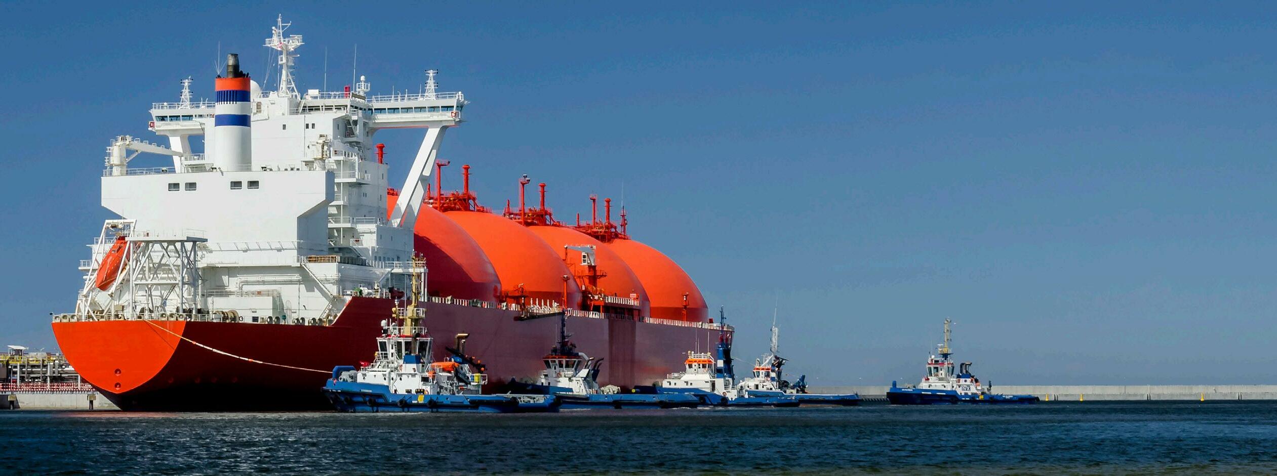
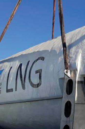
Chantiers de l’Atlantique has chosen Gasum as expert supplier of LNG bunker fuel and technical adviser to perform the initial bunkering of the first LNG-fuelled cruise vessel built in its premises. This first LNG bunkering took place on the 10 September 2022 in the French port of La Rochelle, for which it was also the first LNG bunkering operation. The choice of Gasum as partner in the preparation and performance of this delivery recognises Gasum’s unique expertise in supporting shipyards performing initial bunkerings of new-build LNG-fuelled cruise vessels.
Gasum has successfully performed the initial bunkering of the first LNG-fuelled cruise vessel to be completed by Chantiers de l’Atlantique. The LNG was delivered by Gasum’s LNG bunker vessel, Kairos
In addition to delivering LNG, Gasum has supported Chantiers de l’Atlantique in the technical preparation of the delivery, including obtaining the relevant permits and authorisations. This delivery marks a new milestone in the extension of the Gasum LNG bunkering network and underlines its ambition to grow geographically, offering its expertise to customers wherever such is requested.
Gasum and Chantiers de l’Atlantique share the ambition to improve the environmental performance of the shipping industry by promoting and demonstrating the technical and commercial availability and reliability of alternative fuels, of which LNG is undoubtedly the most mature.
8 October 2022 LNGNEWS 31 October – 03 November 2022 ADIPEC Abu Dhabi, UAE www.adipec.com 29 November – 02 December 2022 22nd World LNG Summit & Awards Athens, Greece www.worldlngsummit.com 16 November 2022 Global Hydrogen Conference 2022 Online Conference www.globalhydrogenreview.com/ghc22 14 – 16 March 2023 StocExpo 2023 Rotterdam, the Netherlands www.stocexpo.com Germany RWE and ADNOC agree
LNG delivery to
LNG import terminal
R WE
01 – 04 November 2022 Americas LNG & Gas Summit & Exhibition Louisiana, USA www.worldlngamericas.com 06 – 07 March 2023 9th International LNG Congress Düsseldorf, Germany www.lngcongress.com
BY DES IG N ®

CLEAN & SUSTAINABLE C O OLE R
C ha r t is at t he fo re f ro nt of t h e t ra nsitio n to a low carbon future through technology, equipment and ser vices delivering hydrogen, LNG and biogas for energy and transpor tation. Our carbon capture technology also removes harmful pollutants including SOx, NOx and mercur y w w w.Char tIndustries.com LNG@Char tIndustries.com
hen it comes to the movement of LNG and other energy commodities around the world, there are many sources of information that are used by organisations to ensure they have an accurate picture of the markets.
Traditional traders, for example, will typically rely on conventional market indicators and data from the likes of Bloomberg, as well as projections and official quotas released by industry bodies, such as OPEC. But they are always on a quest to find more data to gain an edge over their competitors, which is fuelling an increasing interest in alternative data.
Alternative data unlocks the ability to receive insights in real time so that market trends can be derived in advance of official data. For many energy commodities, a number of alternative data sources must be analysed to this end. Coal consumption can be ascertained by increased activity from mines, power stations, and transport operations. With regard to crude oil, global shipping movements and social media activity in Arabic – which accounts for 90% of all social media conversations on crude oil – can be analysed. Of course, tracking energy commodities flows that are largely transported through pipelines beyond what is released by
operators is impossible. However, it is possible to track the movement of oil tankers and LNG carriers, which can be used to provide significant insights on global imports and exports.

The value of shipping data
For LNG, a number of data sets can be used to deliver timely information on global shipping movements. An example of this includes automatic identification system (AIS) shipping data, which allows companies, such as QuantCube, to pinpoint the exact location of vessels at sea and track where they, and other commodities vessels, end up across the globe.
When it comes to identifying vessels, a key benefit of LNG carriers is that they are unique from a design perspective, as they typically have 4 – 6 distinctive tanks and many more features specifically designed for the storage, transportation, and delivery of LNG. For example, LNG is typically stored at a temperature of -126˚C, so the tanks are designed to ensure that the LNG remains cold enough to stay in a liquid state. By using satellite imagery, these vessels can be easily identified. For tankers, however, these vessels might just as easily be carrying
Joao Macalos, QuantCube Technology, France, explores the value of alternative data for delivering real-time insights on LNG and other energy commodities.
10
diesel as crude oil, so other data points must be used to determine what the cargo is.
Of course, tracking ships through AIS data only works when the systems are operational. In most cases, they are, as investment in the transportation of expensive commodities must be safeguarded to provide stakeholders with assurances that cargos will reach their destinations safely. However, some countries, particularly those that might be subject to sanctions, such as Iran, as well as companies operating in these countries, may choose to hide their movements. Conversely, other countries and organisations are eager to show that they are capable of exporting large quantities of LNG to increase investment and confidence in their output. In these cases, shipping-based information may be used to provide a more accurate picture of their exports.

Adapting to crises with alternativedata
Using alternative data to gain real-time insights is crucial for staying a step ahead and mitigating the effects of geopolitical and macroeconomic events. In recent months, the combination of the war in Ukraine and Europe’s deepening energy crisis has caused global LNG prices to skyrocket. Some supply chains have been severely disrupted and the lack of official data from major exporters, such as Russia, has made the situation increasingly difficult for traders, economists, and leading market analytics providers to predict. However, one thing that is certain when it comes to determining investment strategies and commodities trends is that the more data an organisation has, the better equipped it will be. The value of real-time insights on variations in the commerce of LNG, that reveal movements between the world’s leading importers and exporters, cannot be understated.
AIS data, for example, is particularly useful for detecting novel movements of LNG and other commodities as new movements between countries may reveal the opening of new routes, that may in turn reveal wider macroeconomic trends. For example, a significant increase in arrivals of LNG shipments to Italy from Algeria between April and July 2022, compared to the same period last year, reveals that the country is not just stockpiling for winter, as might be expected from many European countries at this time of year, but protecting against future scarcity. Similarly, if imports of energy commodities and, most significantly, iron ore, are seen to increase in a country, it is reasonable to assume that an increase in economic activity and growth will follow, as iron ore is the key raw material used in the production of steel, which is chiefly used in construction.
Combining alternative data sets can also reveal wider economic and political trends. Since the implementation of massive sanctions by Western countries against Russia, AIS shipping data has revealed a significant drop in import-export activity at northern-Russian ports, which are mainly used for trade between Russia and northern-European countries. Looking at the wider picture and bringing in other alternative data sets also helps understand the effect of sanctions among the population. For example, QuantCube was able to determine economic anxiety among the Russian people through examining a number of data sources, such as social media platforms, using cutting-edge natural language processing algorithms to determine economic sentiment. Using these techniques, the company discovered that economic anxiety increased by 250% in March (following the invasion of Ukraine) compared to the level recorded in January. It also found that sentiment relating to emigration spiked significantly in this period, further revealing the wider impact of the conflict.
11
Building in agility
Ultimately, long-term investment strategies cannot be based on real-time insights alone. For this purpose, they must be used in combination with traditional methods of market analysis and indicators. However, the value of alternative data for gaining immediate insights on contemporary events, and adjusting investment strategies accordingly, is significant, as they can provide additional insights to enable investors to anticipate market movements and act before their competitors.
It is no secret that the COVID-19 pandemic severely disrupted supply chains. Again, analysis of real-time AIS shipping data revealed how congestion at the largest ports in the world, including Long Beach (the US), Rotterdam (the Netherlands), and Shanghai (China) between the months of August and September 2021, affected global movements of LNG, dry bulk commodities, liquid bulk commodities, and container ships. Following the congestion, tensions in the gas market became a main driver for the increase in global gas prices, which precipitated an increase in crude oil consumption – particularly in China, as the country sought to maintain economic growth.
When the Freeport LNG facility in Texas, the US, closed due to an explosion at the beginning of June 2022, the fall in US exports was immediately clear from AIS data. Wider analysis of the global market in the immediate aftermath of


the plant’s closure was also intriguing, as US gas prices fell due to a surfeit of the resource within the country. As might be expected, the price of gas in Europe, one of the US’s export markets, rose dramatically (Figures 1 and 2).
Similarly, Russia’s invasion of Ukraine – and the subsequent sanctions it incurred – triggered an energy war between Russia and Western countries that has disrupted the energy markets. By tracking the deliveries of LNG in real time, the EU strategy of stockpiling natural gas ahead of the winter and before the full impact of the sanctions was realised was immediately obvious.
These examples reveal how alternative data can be used to predict the impact of future disruptions to supply chains around the world. The consequences of the fire in the Freeport LNG liquefaction facility should serve as a reminder of the fragility of global LNG supply chains. As recent years have shown, black swan events severely impact global supply chains. A similar crisis in the Middle East or APAC regions could have a much more disruptive effect on the global movement of LNG and other energy commodities. With real-time insights, organisations will be much better equipped to adjust their investment strategies and operations in the face of such events.
Making alternative data work forthe LNG industry
With the global alternative data market expected to reach US$143.3 billion by 2030, growing 54.4% annually from 2022 to 2030, organisations across industries are seeking to harness this resource to uncover insights that might give them an edge over competitors with their investment strategies.1
From QuantCube’s work in the commodities space, it knows investors are eager to tap into new sources of information and expects to see a rapid increase in collaboration with alternative data providers in the coming years. Real-time insights on LNG movements are a compelling example of what can be achieved through the utilisation of alternative data, and its potential to create further value and insights across the LNG industry is considerable.
References
1. ‘Alternative Data Market Size, Share, & Trends Analysis Report By Data Type (Card Transactions, Mobile Application Usage, Social & Sentiment Data), By Industry, By Region, And Segment
Forecasts, 2022 – 2030’, Grand View Research, (2017 – 2020), www.grandviewresearch.com/ industry-analysis/alternativedata-market
12 October 2022
Figure
1.
Natural gas prices in Europe and the USA.
Figure
2.
QuantCube Commodity Indicator – USA LNG exports.

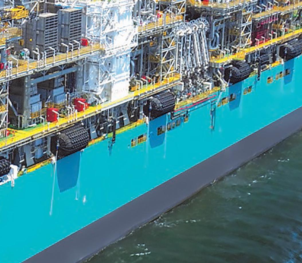
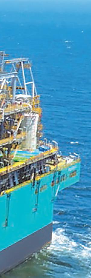
 Figure 1. FSRU Toscana aerial view.
14
he conflict in Ukraine has been a turning point in the European energy market. The issue of energy independence from Russia, in fact, immediately acquired centrality, prompting the European institutions and the member states of the Union to study effective solutions to achieve a rapid diversification of supply sources. The RePowerEU plan, launched in March 2022 by the European Commission, takes on great significance. The Italian government, for its part, has faced the reduction of supplies from Moscow, Russia, by increasing energy links with other supplier countries and at the same time accelerating the storage capacities deriving from its own resources.
In this complex and rapidly evolving scenario, LNG can certainly play a key role. The European Commission estimates that it will be able to replace two-thirds of Russian gas imports within the next year by mainly using LNG. Proof of this is the agreement signed in March with the US, through which Washington undertook to increase supplies to European countries, guaranteeing 15 billion m 3 in 2022, with future increases of up to 50 billion m 3
The FSRU Toscana terminal, managed by OLT Offshore LNG Toscana – a company controlled by Snam and Igneo Infrastructure Partners – can make a decisive contribution to Italian energy independence. Among the main infrastructures of national interest for the import

Giovanni Giorgi, OLT Offshore LNG Toscana, Italy, considers the role of LNG for Italian and European energy independence.
15
of LNG, the terminal currently has a maximum authorised capacity of 3.75 billion m 3/y commercially offered with 41 slots of 155 000 liquid m 3 each.
The regasification capacity is offered on annual and multi-year allocation processes in the months of May and July. If there is still available capacity in the current gas year, the latter is offered monthly during the infra-annual allocation processes through capacity product auctions, monthly and spot auctions, and first come first served (FCFS) in order to maximise the regasification capacity allocation by meeting the ever-changing needs of the energy market.
It should be noted that the auctions held last June for the gas years 2022/2023 – 2032/2033 have shown remarkable results. OLT has allocated, in fact, the entire capacity for the gas years 2022/2023 and 2023/2024. 83% of the capacity per year was then allocated until 2026/2027, which is equivalent to approximately 3.2 billion m 3/y, as well as 5% of the capacity for the gas years 2027/2028 and 2028/2029.
Faced with the energy needs that emerged as a result of the Ukrainian conflict, the authorisation for an increase in the terminal’s regasification capacity would certainly constitute an important step in the implementation of the Italian energy strategy. The studies carried out have shown that the terminal’s capacity could be expanded up to 5 billion m 3 /y in a short time. This increase, which does not involve plant modifications but only an efficiency of logistics, would help to achieve the goal of guaranteeing the security and diversification of the country’s energy supply.
OLT’s commitment is also aimed at the issue of sustainability to make the growth in company activities compatible with protecting safety and safeguarding the environment. During 2021, for example, the climate-changing emissions related to the terminal’s activity were reduced by 7%, not to mention the initiatives to offset carbon dioxide (CO 2) emissions taken by OLT in 2021, such as reforestation interventions through the recovery of woodland areas and the creation of new peri-urban green areas. Furthermore, in support of the fight against climate change, OLT is planning to define a GHG reduction plan with subsequent development of decarbonisation projects.
A key resource in the energytransition process
The changes in the energy scenario caused by the war in Ukraine have contributed to enrich the Brussels agenda with new priorities. The quick breakaway of the EU from Russian energy dependence has joined the broader goal of the energy transition, which sees its milestone in the New Green Deal of 2019. The EU has therefore outlined a clear development strategy. The goal is to become the first climate-neutral continent through total decarbonisation by 2050.
The EU’s objectives are certainly ambitious, but at the same time needed, as also highlighted by the heat and drought of the Summer of 2022. To make them credible, adequate strategic planning and the allocation of significant investments in the energy and mobility sector will have to be envisaged.
In this perspective, natural gas (gaseous or liquefied) can play an essential role, especially in the mobility sector. The gas infrastructures could be converted, in the long term, into the transport and storage of new generation gases, such as biogas or bio-LNG, synthetic methane, or be used for the transport and reception of hydrogen, in the liquid state or mixed with other gases.
LNG, in addition to providing support to the energy system stability when the low production of electricity from renewable sources occurs, thanks to its environmental performance, is one of the fuels that can guarantee the low emissions required for the reduction of CO 2 emissions, sulfur oxides, nitrogen oxides, and particulate in the maritime and heavy land transport sectors, envisaged by the new regulations that will come into force to achieve the zero-emissions targets by 2050.
In the continental context, Italy is at the centre of this change, not only from a geographical point of view. On the one hand, the country has the largest European network of LNG fuel stations for road transport; on the other hand, there are three important regasification terminals allowing to receive LNG from all over the world, providing a key contribution to the security and diversification of supplies.
After the inaugurations of the first two coastal LNG deposits in 2021, which marked a defining moment in the consolidation of the Italian small scale LNG supply chain, 2022 will be the year of the completion of the Italian supply chain: OLT will be the first Italian terminal to provide the small scale LNG service; this service means that small LNG carriers can load LNG directly at the regasification and storage terminal to refuel LNG ships or to deliver it to coastal deposits inside the Mediterranean ports.
Following the authorisation process started in March 2019, in October 2020 OLT received authorisation to implement the modifications to the terminal necessary to launch the service. Following a study on logistics that has deepened the reception capacity of the terminal, confirming the possibility of receiving a greater number of small LNG carriers than the authorised one, OLT has decided to increase the flexibility and efficiency of the terminal by undertaking a new authorisation path, in progress at the moment, to allow the berthing of up to 122 small scale LNG carriers a year.

16 October 2022
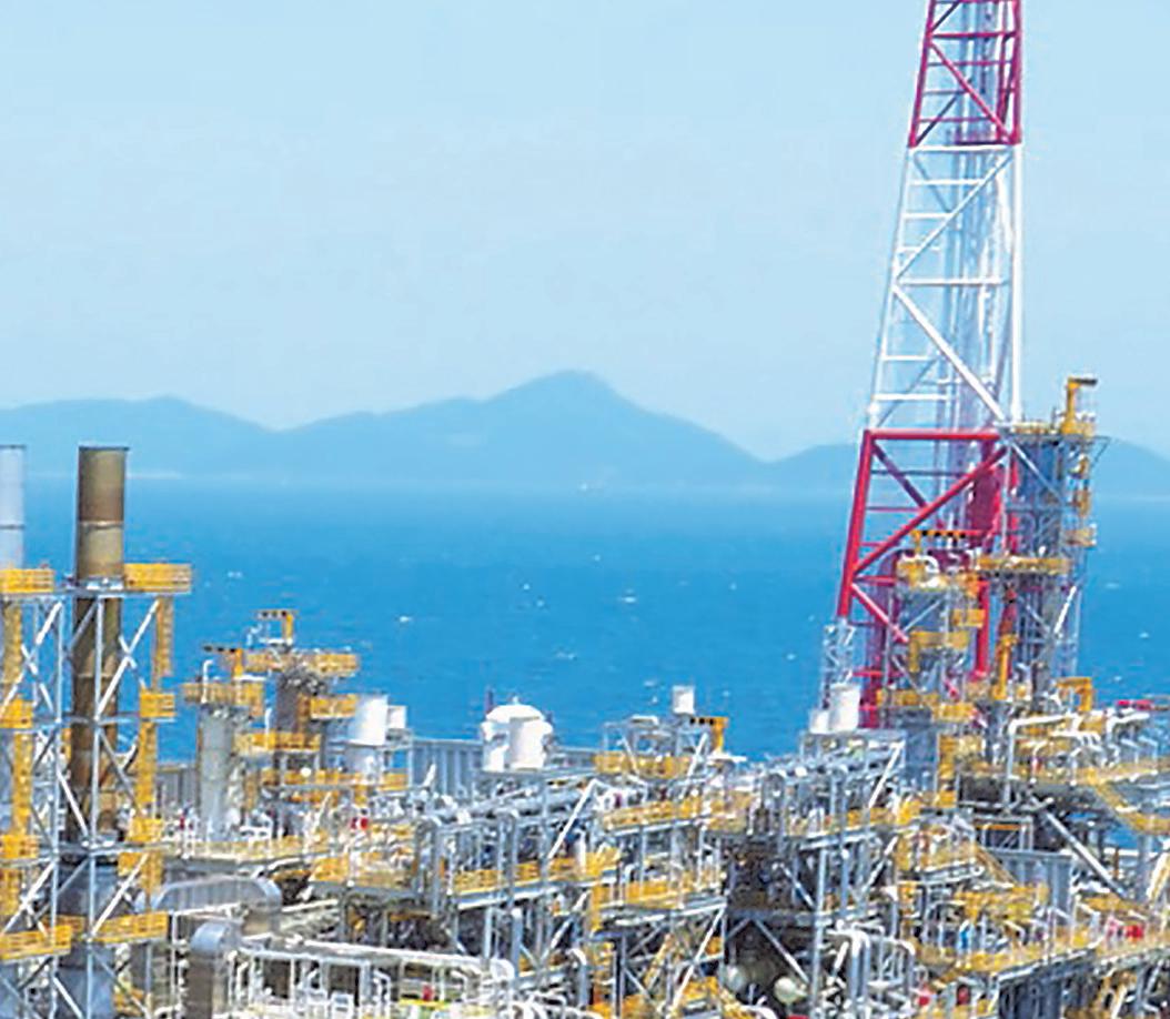
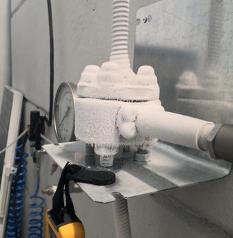
Figure 2. Ship-to-ship operations at
FSRU Toscana
Of the LNG marine expansion
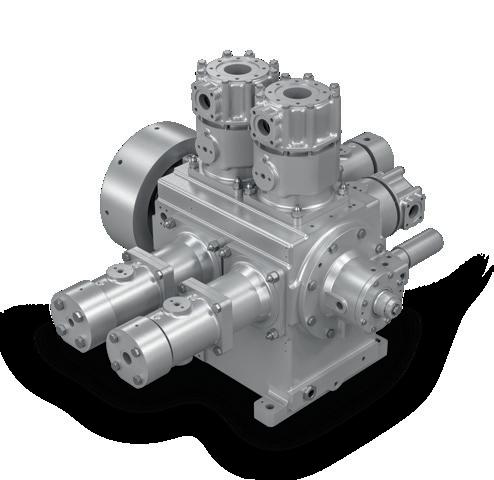
All the key role players in the marine industry have started to invest in LNG technology and infrastructures, as well as in new dual fuel or gas only engines for ships and new LNG bunkering vessels too. Vanzetti Engineering ARTIKA Series submerged pumps and VT-3 Series reciprocating pumps are the default choice for low and high pressure marine engine fuel gas systems, stripping and spray applications, booster, ship to ship bunkering, cargo and more.
VANZETTI
ENGINEERING. Widening the horizons of LNG sustainability. www.vanzettiengineering.com
FSRU Toscana will be able to receive small scale carriers with a maximum length of 120 m, corresponding to a capacity of approximately 7500 liquid m 3. The mooring system, the manifolds, and ESD will be in accordance with OCIMF and SIGTTO recommendation.
From a commercial point of view, the service will be offered, as soon as the works are completed, in a non-discriminatory manner and on an auction basis via the regasification capacity allocation platform (PAR) managed by Gestore Mercati Energetici (GME).
This service is of fundamental importance, considering that the LNG currently used in the Italian small scale LNG logistics chain is totally imported from abroad. This will allow the completion of the supply chain of LNG as a fuel, not only for maritime transport but also for land transport, as well as for civil and industrial uses in areas not supplied by the national gas grid.
The centrality of LNG in the transition towards a sustainable society therefore rests on three areas: marine, road transport, and distribution. In the marine sector, the use of LNG is compliant with the limits imposed by the International Maritime Organization (IMO) in the ‘SECA’ sulfur emission control areas; from 1 January 2020, the North Sea, the Channel, and the Baltic Sea have become part of these areas, while it has already been proposed that the Mediterranean Sea will also be part of them as soon as possible (it is expected that this proposal will come in force on 1 January 2025). The fuels used today in those areas by container ships, ferries, cruise ships, and other
merchant vessels must comply with a sulfur emission limit of 0.5%, a significant step forward compared to the previous maximum allowed value (3.5%). In land transport, the use of LNG allows considerable savings in terms of climate-changing emissions, as it does not contain particulate and contributes to noise reduction. The vehicles, as well as ships, that choose this type of power supply also have an important advantage for the future: being able to use the renewable option of LNG (bio-LNG), and not only the fossil one.
Main features of the terminal
The FSRU Toscana floating terminal, through which OLT guarantees the storage and regasification of LNG, is one of the main infrastructures of national interest for the import of LNG serving the development and autonomy of the Italian energy system.
Permanently anchored approximately 22 km off the coast between Livorno and Pisa in the Tuscany region, the terminal, which entered into commercial operation in December 2013, contributes substantially to the Italian gas system, guaranteeing the security and diversification of the country’s energy supply with approximately 5% of the national requirement covered.

The terminal is energetically self-sufficient, using the boil-off gas (BOG) to produce the energy needed for operations.
OLT is authorised to receive approximately 90% of the current LNG carrier fleet, in particular those with a cargo capacity between 65 000 m 3 and the new panamax class (approximately 180 000 m 3); Wobbe Index system installed on board, which makes it possible to correct the quality of LNG in terms of calorific value, adapting it to the specific requests of the national network, allows the reception of most of the LNG produced in the world. The contribution that FSRU Toscana provides to the diversification of supply is confirmed by the receipt of LNG cargoes arriving from the main exporting countries such as Algeria, Cameroon, Egypt, Equatorial Guinea, Nigeria, Norway, Peru, Qatar, Trinidad and Tobago, and the US.
Furthermore, users of the regasification service can take advantage of additional services such as flexibility ones. Specifically, nomination and renomination service, virtual liquefaction service, and extended storage service.
The nomination and renomination service allows the user of the regasification service to modulate, even within the same day, the quantity of LNG regasified and redelivered at the entry point of the national grid or at the virtual exchange point (PSV), according to the timing and procedures set out in the regasification code.
The virtual liquefaction service allows the users to deliver natural gas at the PSV by receiving an equivalent quantity of LNG inside the terminal tanks. Such LNG can be either received, as liquid, into small scale carriers or, as natural gas, at the entry point of the national grid.
The extended storage service consists in providing to the regasification users a temporary storage service for a quantity of LNG inside the terminal tanks, which could be redelivered as liquid onto small LNG carriers or regasified and sent into the national grid in a period other than the one in which such LNG was discharged into the terminal.

18 October 2022
Figure 3. FSRU Toscana T16.
Figure 4. Simulation of a small scale LNG carrier approaching the terminal.
here is a growing demand across the energy industry to reduce greenhouse gas (GHG) emissions, prompting governments, utilities, and consumers to seek out cleaner energy alternatives.1
Hydrogen is quickly gaining interest as a substitute for fossil fuels since its combustion produces only water with no carbon emissions. Green hydrogen is produced from water using an electrolyser with renewable electricity as the power source. Renewable electricity is often generated from solar, wind, hydropower, or even nuclear power, which is also considered a green power source.
One method to quickly integrate green hydrogen into the power grid is by displacing a percentage of natural gas in the existing natural gas distribution network with hydrogen. If the percentage of hydrogen is kept to an appropriate level, there is minimal impact to gas consumers. Utilising the existing gas infrastructure also provides a significant environmental benefit as it relates to construction
requirements associated with implementation.
CB&I recently completed a green hydrogen production and pipeline injection project in Howell, New Jersey, the US. In that particular case, green hydrogen is produced from water, an electrolyser, and solar power. The hydrogen displaces a limited percentage of the natural gas in the gas distribution network, resulting in a cleaner hybrid fuel without significant impact to the operation of standard household gas appliances.
For now, these projects are limited to smaller, locally isolated networks, but as the concept is proven, more widespread hydrogen displacement into natural gas pipelines will occur with concentrations potentially as high as 20%.

Hydrogen impacts to LNG peak shavers
Though the limited presence of hydrogen in natural gas has minimal effects on residential appliances and
Jeffery J. Baker and Randall W. Redman, CB&I, USA, detail how hydrogen can impact LNG peak shavers, outlining the solutions to keep LNG peak shavers operational.
19
industrial burners, even a small percentage of hydrogen in the feed gas to LNG peak shaving facilities will affect the liquefaction process.
Hydrogen in natural gas will change the load on the liquefier and may even limit the liquefier’s production availability. Gas utilities need to be mindful of the impacts that hydrogen injection into the natural gas grid can have on their peak shaver liquefaction operation.
This report outlines the impacts caused by hydrogen in the feed gas and what facility modifications may be required if the natural gas feed contains hydrogen. When possible, it is highly recommended that hydrogen injection be located downstream of an LNG peak shaving facility to avoid issues with liquefaction. However, given the widespread interest in the hydrogen displacement concept, it is possible that hydrogen will become a common constituent in natural gas.
Typical composition of natural gas
A typical natural gas pipeline will have a composition similar to that shown in Table 1. A phase diagram for this composition is shown in Figure 1. A standard LNG peak shaver will liquefy the natural gas at pressures between 30 atm and 55 atm (440 psia and 800 psia). Figure 1 shows

Table 1. Typical natural gas composition
Component Mole fraction
Methane 0.9381
Ethane 0.024
Propane 0.0065
i-Butane 0.0005
n-Butane 0.0005
i-Pentane 0.0002
n-Pentane 0.0002
Nitrogen 0.02
Carbon dioxide 0.01
that as a natural gas stream is cooled to 212˚K (-78˚F) at 40 atm, the gas stream begins to condense with the heavier components in the natural gas condensing first. As the stream continues to cool, more liquid is formed. At approximately 188˚K (-121˚F), the gas stream is fully condensed. A standard LNG liquefier will continue to cool the stream to a sub-cooled condition as cold as 111˚K (-260˚F).
Natural gas with varioushydrogen concentrations
Hydrogen in the natural gas stream will have a dramatic effect on the phase diagram. Figure 2 shows a natural gas stream with an increasing hydrogen content from 2% to 20% hydrogen. With an increasing amount of hydrogen in the mixture, the point where the mixture can be fully condensed occurs at lower temperatures. This alone means a liquefier requires more energy to condense a mixture containing hydrogen. However, another effect is also present.
As the temperature is lowered, the dew point line for the mixture begins to turn upwards. This means that as the mixture gets colder, it may fully condense, but continuing chilling may create vapours again at lower temperatures. This is unusual for typical liquefaction processes. Typically, once a stream is fully condensed, any further cooling will sub-cool the liquid. However, the hydrogen causes vapour to form and the mixture becomes two-phase again at lower temperatures.
As seen with a 3% hydrogen mixture in the natural gas, at the 40 atm pressure, the mixture starts to condense at a similar temperature to the typical natural gas composition of 212˚K. However, this mixture needs to be chilled to 168˚K to become fully condensed. This is much colder than the 188˚K of the typical natural gas mixture. Note from the curve that if the mixture is further chilled to 105˚K (-270˚F), vapour starts to reform. Typically, LNG peak shavers would not operate at this low of a temperature, therefore the 3% mixture should remain liquid.
Now, consider a 5% hydrogen mixture in the natural gas at the 40 atm pressure. Condensation begins at 212˚K. As this mixture is cooled, more vapour is condensed; however, regardless of how cold the mixture is, it will never achieve full condensation. In other words, there will always be vapour present at 40 atm. The mixture would need to be at a pressure of 50 atm to reach full condensation, but then at temperatures colder than 135˚K (-216˚F), vapour will form again.
At hydrogen concentrations of 20% in the feed gas, there is no pressure where this mixture will be fully condensed. There will always be vapour present.
The data in both Figures 1 and 2 has been generated using AspenTech’s HYSYS with a GERG-2008 Equation of State (EOS). The results for the low temperature effects generated by this EOS correlates with published data in the paper, ‘A Phase-Equilibrium Apparatus for Gas-Liquid Systems and the Gas Phase of Gas-Solid Systems: Application to Methane-Hydrogen From 66.88˚K to 116.53˚K and up to 125 Atmospheres’ by B. S. Kirk and W. T. Ziegler from the Georgia Institute of Technology, Atlanta, Georgia, the US. 3
20 October 2022
Figure 1. Phase diagram for natural gas.2
Challenges with hydrogen inLNG liquefiers

This inability to fully condense the hydrogen-natural gas mixture can have dramatic effects on existing natural gas liquefiers. If the process was originally designed for full liquid interfaces within the existing liquefaction equipment, then the equipment may not have the capability to handle two-phase conditions with vapour present in the streams.
For example, the fins in a brazed aluminium heat exchanger are designed for the liquid transition of the natural gas stream load curve matching the refrigerant curve. If the mixture remains two-phase at the temperature expected for full condensation, a pinch within the heat exchanger may occur that cannot be overcome. A pinch is where the load stream temperature approaches the refrigeration stream temperature such that temperatures further down the exchanger will not be as cold as originally designed. The result is that production rates may be compromised.
The presence of two-phase fluids at the bottom of the exchanger will change the heat transfer co-efficients, which will further reduce the heat transfer for the fixed sized exchanger, compounding the effects. In addition, downstream piping and valves that were designed for single-phase liquid will have large pressure drops due to two-phase flow and may not function as designed.

This indicates that for a liquefier to reach full liquid formation, the hydrogen content needs to be less than approximately 3% in the natural gas. However, even with the hydrogen content reduced to this lower value, there still may be issues with the boil-off gas (BOG) from the storage vessel.
Process simulations performed by CB&I show that an LNG mixture with 3% hydrogen will have up to 16% hydrogen in the BOG due to flash and storage vessel heat leak. This high hydrogen content in the boil-off may cause problems with BOG equipment, such as boil-off compressors or reliquefaction of the BOG. If the BOG is returned to the natural gas distribution system, the resultant tail gas may encroach on pipeline component concentration limits.
BOG compressors will be affected if the BOG contains high percentages of hydrogen. If the gas contains 16% hydrogen, then the mass flow through a compressor will be reduced for compressor volume flow due to the lower density created by the inclusion of hydrogen. For centrifugal machines that operate at a defined head, the presence of hydrogen will lower the discharge pressure. For positive displacement machines that operate at a defined pressure ratio, the discharge temperature and power will increase.
BOG compressor oil and shaft seals will need to be reviewed for compatibility with hydrogen. Due to the low mole weight of hydrogen, these seals may allow the hydrogen molecules to pass through easier than the larger methane molecules. The compressor oil may not be compatible with hydrogen. Material specifications for the compressor and downstream equipment, including piping, will need to be reviewed to ensure that the hydrogen does not cause hydrogen embrittlement or stress corrosion issues.
If it is found that the hydrogen in the BOG gas prevents the BOG compressor equipment from operating properly, then a reduction of the feed gas hydrogen to less than 3% may be required, even though the liquefaction process can

VACUUM JACKETED VPIPE ACUUM JACKETED PIPE We provide a comprehensive component offering to complete our system design, manufacture, and installation capability. www.ACMECRYO.com www.ACMECRYO.com 8800.422.2790 00.422.2790 Our application-specific accessory product lineup offers the optimum system solution for any application. Including Liquid Nitrogen, Oxygen and Cryo Liquid Piping.
handle the higher hydrogen content. Alternatively, an additional separation process will need to be added to the BOG to remove hydrogen.
If the BOG is used as fuel gas within the facility, the hydrogen will change the heating value and density of the fuel gas. Storage tank pressure relief valves will need to be checked for proper sizing with a high hydrogen content in the tank vapour space.
The effect of hydrogen on the risk of LNG rollover in the LNG tanks is not well known. Additional studies will be required to determine if the small amount of hydrogen remaining in the LNG can increase rollover effects in stratified LNG tanks.
Solutions to keep LNG peak shavers operational
The simplest solution, of course, is to avoid having hydrogen in the feed gas to a peak shaving facility when possible. Gas utilities that are considering adding hydrogen displacement into the distribution systems should carefully assess the location of the injection point to avoid the inlet of the peak shaving facility, as was done at the Howell facility.
Over time, it is possible that hydrogen will become prevalent in many of the pipelines feeding peak shaving facilities. This will require mitigations to keep these important facilities operational.
For existing liquefiers, hydrogen removal is recommended prior to the liquefaction process. The simplest arrangement may be to install a separation process prior to the gas pre-treatment system (Figure 3). A solution for an existing LNG facility is membrane separation.
With this process, the mix of hydrogen and natural gas will enter a membrane vessel where the natural gas would pass through while the hydrogen is separated and exits as a low-pressure stream. While 100% separation is not achievable, suitable separation required for LNG liquefaction to continue is likely for a properly designed and installed system.

New facilities may be able to include a separation process within the LNG liquefaction process. This may be a distillation process extracting the hydrogen gas from the liquid LNG stream. However, the refrigeration system would need to be designed for this separation within the liquefaction process. This would preclude such modifications to existing LNG peak shaver facilities.
Handling extracted hydrogen
After the hydrogen has been extracted from the natural gas, there are many ways to handle the hydrogen gas. The easiest method is to vent or flare the gas. For the membrane separation option, the separated hydrogen is at a low pressure and can be easily sent to a low-pressure flare. Hydrogen is not considered a GHG and therefore does not have the same effects on the environment as carbon dioxide or methane.
Alternatively, the hydrogen could be compressed and returned to the pipeline, provided there is enough flow-by in the pipeline so that the hydrogen does not recirculate back into the feed stream of the facility.
Depending upon the quantity of hydrogen separated, the hydrogen by-product may be a useful commodity. Hydrogen may be compressed for storage or liquefied and then sold as a revenue stream. It may also be beneficial to capture the hydrogen for resale or consume it on site as fuel gas. Other options for the hydrogen are to produce green electrical power or fuel for hydrogen vehicles. Depending on the hydrogen’s intended purpose, additional equipment may be necessary to purify the hydrogen extracted by the separation process.
Additional considerations and consultation
Figure 2. Phase diagram for natural gas with various concentrations of hydrogen.2

Although this article summarises the challenges and potential solutions to mitigate the presence of hydrogen in feed gas for peak shaving facilities, specific conditions must be evaluated before recommendations can be developed for implementation.
Companies, including CB&I, offer consultations based on the design parameters of the facility and can make recommendations that take into consideration the specific concerns of the owner and/or operator.
References
1. ‘Global Methane Initiative – Importance of Methane’, U.S. Environmental Protection Agency, (30 June 2021), www.epa.gov/gmi/importance-methane.
2. Curve data by AspenTech HYSYS Process simulation software for values from Table 1 using GERG 2008 Equation of State.
Figure 3. Diagram of hydrogen separation from natural gas feed into an LNG peak shaver.
3. KIRK, B. S., and ZIEGLER, W. T., ‘A Phase-Equilibrium Apparatus for Gas-Liquid Systems and the Gas Phase of Gas-Solid Systems: Application to Methane-Hydrogen from 66.88˚K to 116.53˚K and up to 125 Atmosphere’, International Advances in Cryogenic Engineering, Vol. 10, Part 2, Timmerhaus, (1965).
22 October 2022
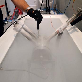
While the current focus is on the decarbonisation of maritime transport, the protection of marine biodiversity remains a major environmental challenge for all stakeholders in the maritime sector.


Even if ballast water is critical to safe and efficient shipping operations, it can pose serious ecological, economic, and health challenges. According to the latest 2017 report The GoBlast Story, co-ordinated by the International Maritime Organization (IMO), the Global Environment Facility (GEF), and United Nations Development Programme (UNDP), more than 7000 organisms are transferred in ballast water every hour of every day.
Every year, 10 billion t of ballast water are transported around the world, dramatically increasing the risk of invasion of unwanted organisms during discharge in the arrival port. The preservation of marine biodiversity is one of the 17 sustainable development goals adopted by the United Nations.
Although the Ballast Water Management Convention (BWM Convention) has set criteria for ballast water treatment to limit the risk of unwanted invasions, these requirements entail significant investments in onboard systems and additional costs for operation and maintenance of ballast tanks.
However, the best pollution is the one humans do not produce. The operator then becomes 100% compliant without any treatment or investment; a ballast-free solution.
Based on this assumption, GTT studied several concepts before presenting a totally reliable and operational solution. The basic idea is to obtain a somewhat higher draft in the design load case, and by that, maintain also a sufficient draft for safe navigation, even when empty.
To overcome these issues, GTT considers that the most suitable form is a V-shaped hull design and has conducted extensive tests on a ballast free bunker vessel. This design takes full advantage of the specific geometry of the membrane: the hull
Lorenz Claes, GTT, France, discusses the possibility of LNG carriers operating without ballast water, highlighting how this would be beneficial both from a technical perspective, as well as the preservation of marine biodiversity.
23
lines and the incorporated membrane tanks are designed to fit perfectly, and the free surface effects of LNG are reduced when the vessel is partially loaded.
A long story of development
For several years, GTT has continued to innovate by offering new solutions to the maritime world. Several projects have been developed in conjunction with various designers and shipbuilders to propose LNG carriers able to operate without ballast water.
Two major studies have led to sloshing test campaigns in GTT’s R&D centre, and some of them have obtained approval in principal (AiP) from classification companies, proving the feasibility of such a concept. These successful results have confirmed the company’s commitment to propose a safe ship concept. The results also confirmed GTT’s decision to choose the containment system

Mark III Flex. The insulation foam density is standard 130 with partial 150 kg/m3. The design boil-off rate with the above values is 0.165%vol./d.
GTT developed a new concept for a vessel through building on the experience gained on the previous ballast-water-free projects, as well as the recently constructed membrane-type LNG bunker vessels. The vessel may serve either as an LNG bunker vessel or as a regional feeder.
The design proposes numerous advantages, such as reduced investment and operating costs, simplified operations, reduced corrosion, and a prolonged lifetime.
The general dimensions are:
Length x beam x draft = 141 x 25 x 7.25 m
For a cargo volume of 18 700 m3 at a design speed of 14 knots.
Two identical cargo tanks are provided for simplified operations, and a very effective anti-roll tank (ART) system is provided in the vessel’s fore part.
The vessel uses a twin-screw azimuth propulsion system, increasing the manoeuvring performance and providing a high-power reserve in harsh conditions when empty.
The ship produces reduced emissions than a conventional vessel, as it has a lower level of consumption. On average, there is a power reduction of over 10% versus a conventional vessel.
Specific issues such as pilot boarding, trim regulation, and dry docking were identified, investigated, and solutions validated by the design.
In coastal trades, with frequent calls to major rivers, the benefits are substantial.
Ship design general aspects
Trim-management is one of the important design issues for such a vessel: careful longitudinal distribution of weight and buoyancy is made by design, and a genuine trim-water system is provided, using some dedicated fresh-water that is permanently on board. The trim can always be managed in a satisfying, rule-compliant way. The vessel is designed in fully loaded condition at zero-trim and in empty condition with some aft-trim, which improves the propeller immersion. In this respect, the use of a bulbous bow shape was not beneficial, also with regard to often changing drafts when operating as an LNG bunker vessel.
The cargo tank filling can be at any level without restriction, as demonstrated by the liquid motion campaign. The operator simply has to ensure the vessel trim is in the required range –from zero-trim to approximately 1.5 m aft or possibly 1 m forward – and compliant with visibility rules.

Roll-motions are effectively reduced by substantial bilge-keels and further by the ART. The installation in the forward part is ‘ideal’, as the space is available without any cargo loss. The ART design is made for the vessel in empty conditions, but it may also be used in loaded conditions with somewhat reduced effect. The operation of the ART is optional, not mandatory, and it uses the onboard trim-water without losing cargo-deadweight.
The question of parametric rolling was assessed by HSVA, the Hamburg ship model basin, and can be totally excluded due to the specific hull shape.
Effective construction is kept in mind for easy assembly and inspection of the hull structure. The full double structure (bottom, sides, and also the upper deck) is mainly composed of void spaces giving substantial advantages compared to a ballasted structure.

24 October 2022
Figure 1. 18 700 m3 LNG feeder and bunker vessel Shear-Water.
Figure
2.
Shear-Water mid-ship section vs conventional vessel.
Figure
3.
Incorporated model tank on board. (Source: HSVA).
Passion for innovation and technological excellence serving a sustainable world

With almost 60 years of experience, GTT is the partner of choice to design cutting-edge technological solutions for an improved energy efficiency. We bring our passion for innovation and our technical excellence to the service of our customers, in order to meet their transformation challenges both for today and tomorrow.

Our expertise goes from LNG ships to LNG-fuelled ships. We support all your LNG related operations, train and assist your crews to optimise your vessel economics. As shipping is turning digital, GTT Digital proposes Shipping Solutions, combining our experiences and skills to offer a wide range of digital services to the maritime industry.
The GTT teams are at the heart of our mission. Committed and united, we are determined to contribute to building a sustainable world.
gtt.fr
Docking is made in the same way as any ship: even in empty condition, the vessel can be put in even keel to avoid hazard, and the provided large keel plate with supporting side girders assures the required transverse stability even when dry, without further side supports.

The vessel outfitting is proposed on a state-of-the-art basis. Latest knowledge from other LNG bunker vessels is considered for user benefit.
The propulsion system is chosen with dual-fuel electric power generation based on three identical gensets and two azimuth propellers (design provided by Schottel) driven by electric motors. Such a configuration gives the best flexibility, high redundancy, and best economics for all operations.
The Shear-Water design is evaluated, based on the present propulsion system, to be EEDI compliant for ordering the vessel before 2030. Further improvements may be incorporated over the detailed design process, in close co-operation with the chosen classification society.
How to address the key concepts for a ballast water free vessel
Some of the key design aspects are the hydrodynamics and in-tank liquid motions (sloshing).
On behalf of GTT, an extensive test-campaign was made by HSVA. It validated the ship’s behaviour in calm-water and the vessel seakeeping in severe sea-states. The membrane system was validated in GTT’s laboratory for worldwide conditions without any filling restrictions.

Both of the campaigns showed results ranging from good to excellent.
Hydrodynamics
The tests were made with a self-propelled model in a scale of 1:18, a length of 7.75 m, and a laden weight of 2.8 t.
Classical calm water tests covered speed-power and manoeuvring. The outcome showed a power reduction of
10 – 15% for the range 10 – 14 knots, when considering average values between fully loaded and empty conditions. All of these were compared with a same size and same function conventional vessel.
Manoeuvring tests showed results exceeding IMO requirements and expectations. The design shows perfect course keeping, combined with excellent manoeuvring capabilities.
Seakeeping performance was tested in selected sea-states up to NATO Sea-State 7 (Hs 7.5 m). No unusual, excessive, or dangerous behaviour in the selected sea-states has been observed. Observations were similar to other ships in such conditions.
Tests and investigations covered motions and accelerations, rolling, including parametric excitation, slamming, propeller immersion, green water, and speed loss in waves.
Course keeping in waves is considered good, and the ship was never found to be out of control.
Further tests were made for pilot transfer operations. Comparative tests with and without ART showed a roll reduction of approximately 60%.
Additional separate tests were made with the incorporated (single) LNG tank, investigating coupling effects between tank liquid motions and external wave excitation.
Cost reductions go with betterenvironment
First estimates show a cost reduction of approximately 5% in terms of CAPEX, as there is no ballast water system (pumps, valves, and pipes, smaller sea-chests) nor treatment system (BWTS) and a reduction of air vents and sounding pipes control.
On the operational side, an annual reduction of approximately US$100 000 – US$200 000 can be expected thanks to fuel savings due to power reduction when empty (smaller displacement), and a reduction of energy consumption with the lack of ballast water system, no pump power consumption, consumables, and spares. Maintenance costs are also reduced by eliminating ballast tank coatings, ballast tank anodes, ballast tank paint, and no more maintenance due to sediments. This saves a lot of time and savings due to less cleaning work during dry-dock. Emissions are also reduced by 10 – 15% compared with a conventional vessel.
Conclusion and outlook
The tests conducted by GTT have shown the feasibility of the concept. In the near future, there will be more and more ships sailing without ballast water. This is great progress from a technical perspective, as well as for the preservation of marine biodiversity.
GTT believes that this concept is completely replicable in other market segments, and the company are convinced that it will see tankers, container ships, and other merchant ships without ballast water in the coming years.
Several classification societies have issued AiP’s, including China Classification Society, Det Norske Veritas, and Bureau Veritas. This development project has demonstrated that this kind of ship is more efficient, more environmentally-friendly, and less expensive to build and operate.
26 October 2022
Figure 4. Side view of the concept design. Figure 5. Test model in the HSVA pool.
Geir Moholt, Høglund Marine Solutions, addresses the importance of system integration as the adoption of new fuels, such as LNG, increases complexity on board ships.
ooking back on 2022, one of the overriding themes when it comes to the future of the global shipping fleet will be ‘keeping options open.’ With a lack of certainty when it comes to the eventual fuel mix of the future, but plenty of pressure to switch away from fossil fuels, the shipping industry is a college student waiting until the last minute to pick their major. And rightly so – after all, it is still far too early to predict how a radically different fuel supply chain will evolve over the lifetime of a vessel. The answer to this dilemma, overwhelmingly, is the option to handle LNG, which keeps the door open for bio- or synthetic LNG, ammonia, or even hydrogen, with some modification. Earlier in 2022, Clarkson Research Services reported that 63% of orders in gt terms have been for alternative fuel-capable units. LNG remains the leading choice of fuel, and many owners are also opting for dual-fuel options.
Managing these fuels effectively will be a challenge in itself. These fuels will require dedicated automated fuel management and supply systems that are far more complex than the current standard shipping is used to, which is based around managing heavy fuel oil (HFO). How shipowners, yards, and equipment

27
suppliers specify and then subsequently use these systems will have a major impact on the overall reliability and performance of future vessels, both newbuilds and those retrofitted to use future fuels. The same goes for LNG carriers and bunkering vessels.
Retrofits of dual-fuel systems can partially de-risk the choices of today and future-proof the investment decisions made amid ongoing fuel uncertainty. By considering how energy can be transferred, stored, and used on board a vessel today and in the future, as well as identifying the similarities and compatibilities across different energy carriers, shipowners can equip their vessels with a multiple use dual-fuel system and eliminate the need for immediately choosing between LNG, ammonia, and methanol from a fuel handling perspective.
A vessel equipped with a dual-fuel system where one fuel system is designed for handling a low vapour pressure combustible liquid at ambient pressures and temperatures, and the other to handle a cryogenic, pressurised combustible and toxic energy carrier – both feeding into an internal combustion engine – will most likely cover any option the future might bring.
With a standard dual-fuel system that can manage HFO/diesel and LNG, the diesel fuel handling side can also be eventually converted to handle synthetic or biofuels, with relative minor impact as long as this is considered from the start. Meanwhile, the other part of the dual fuel system – the one typically handling the LNG – can be made to handle ammonia and hydrogen in the future.
Choosing an integrated automation system (IAS) is more important today than it has been in the past because the number of subsystems with their own control system is increasing and creating huge operational challenges for shipowners. Additionally, system upgrades are becoming especially challenging.
Choosing the right level ofintegrated automation
Modern IAS on board LNG vessels consist of thousands of input and output signals with widespread signal interfaces and functions. The system solves many tasks, which alone can be trivial, but, put together, become complex.
Many onboard systems – such as fuel gas supply systems (FGSS) – are delivered as turn-key solutions that come with their own proprietary control system, which can either become integrated into a vessel’s IAS or run in parallel to it, where only the interface between the two has to be specifically tested on installation. This is a low-risk option for shipyards as it avoids many potential problems during commissioning.
However, using a default control system may not be the best option. Yards and owners can choose a dedicated IAS supplier that provides input/output modules, processing power, and user interfaces. All control functions are delivered within this system, making it easier to fix problems and implement modifications. This can require more effort on the shipyard’s part, as it needs to define the scope of the system – but, ultimately, it can be worth the effort in the long run.
With an updated integrated automation and control system, detailed information from different subsystems is available on a single screen; data logging and storage is simplified, and the crew can access the data banks that detail the day-to-day operations of the ship’s critical systems. Consequently, they can analyse and identify the root cause of faults and make decisions that will improve reliability. One person can debug a problem all the way down to input/output level, rather than finding that a bug exists within a proprietary control system which they cannot access, and needing to await support form the company that supplied it.
In addition, it means that just one company is responsible for the IAS, and there is a single point of contact for all automation concerns in the event that further support is needed – there is no need to work with multiple suppliers to fix a problem that might exist in any of their products. Hardware, spare parts, and user interfaces are also consistent, which makes replacements and upgrades easier, and training is simplified.
Unexplained events
When a ship is sailing, troubleshooting and repair capabilities depend on the training and tools available to the crew. Systems reliant on programmable logic controllers can experience unexplained events from within various sub-systems, and it can be difficult for crews to recreate problems and fix them.

With outdated automation systems, expensive engineer callouts are often required to mend periodic system faults. The engineers will ‘patch’ the system, but will often not find the root cause of the problem because the data outputs from system logs are outdated, unreliable, and inaccessible.
Even more modern subsystems may appear to be working, but there is no guarantee they are operating properly or optimally. Crews may accept this if they cannot find the problem but can find a workaround.
Having invisible unreliability within an automation system can be a significant financial burden for shipowners, often without them even knowing about it. With time, the cost
28 October 2022
Figure
1.
Høglund engineers at work.


of maintaining an old system will outweigh the expense of an entirely new automation system on board.
Update with care
Shipowners looking to update their automation system should consider their approach carefully or risk spending more money on a method that initially seems cost-effective but ultimately comes with considerable overheads. One suggested measure is to start with an upgrade of the ‘top-system’, which includes operator stations and graphics. Then, at the next yard stay, providers upgrade the ‘bottom-system’, including major hardware components such as computer processing units and input/output cabinets.
While this approach may seem reasonable as the cost is spread over a number of years, owners can effectively pay twice for automation refits and get locked into contracts with hardware suppliers with no flexibility on upgrade options. The complete refit of an overarching integrated automation and control system will amount to approximately 60 – 80% of the cost of the step-by-step approach.
By combining the automation systems into an overarching integrated automation and control system, owners also get the financial benefits of automation in much the same way they would by buying a modern newbuild. Complexity is reduced, reliability is increased, and day-to-day maintenance is made significantly easier. Owners and crew are then also able to leverage other cost-saving benefits through improved energy management performance.
Efficiency gained from integrated automation provides a gateway to big data utilisation. Many onboard systems need to interact with each other and generate huge amounts of data while doing so. This information can either be a burden for crew or shoreside teams to manage or a source of valuable operational insights. If handled correctly, it can be used to optimise operations, diagnose faults, and ensure more reliable operations.
Teamwork is critical
Due to the specific regulatory requirements for LNG as a fuel, it is more important than ever that designers, yards,
engineers, automation experts, and system integrators understand the benefits of working together to meet the high safety and reliability standards that shipping demands. There are considerable engineering challenges to effectively integrating automation and gas handling systems on gas newbuilds, for example. Without properly considering automation and integration, the vessel is at risk of becoming difficult to operate and maintain.
Overcoming technical challenges
LNG bunkering vessel design has presented a series of technical challenges that have required specialist expertise. Høglund Marine Solutions delivered the IAS to the MV Cardissa, an LNG bunkering vessel operating for Shell Western LNG. 1 Back in 2017, this was a new type of small scale LNG vessel, and it was necessary to change many details from initial specifications as Høglund worked with its clients to develop the best solutions for this emerging segment.
While most of the components installed on board were standard, the way they were to be used differentiated from typical operation principles. Høglund used its software knowledge to customise the system to give the operators an overview of the plant while also ensuring control loops were working as intended. In this instance, Høglund’s playback functions were particularly important, which allowed crew and operators to analyse events on the level of individual inputs and outputs. On such a complex vessel, this was essential.
Another challenge was how to measure and report fuel consumption from boilers, engines, and gas combustion units when calculating delivered LNG fuel for bunkering LNG-powered vessels. Since the custody transfer system was a standard delivery, it was not that easy to add another calculation to the system, but the equation was known, and the IAS had the data – therefore, the function was implemented there.
Better performance
A large part of the world’s fleet sails with non-optimal systems when it comes to automation and control. Driven by environmental regulation, the number of systems on board modern vessels is rapidly increasing and becoming more diverse and complex. By giving more care and attention to the fields of integration and automation, owners and operators will be able to more effectively drive fuel savings, improve environmental performance, and provide owners and operators with a more accurate overview of a ship’s performance and operational data in compliance with regulations.
References
1. ‘Høglund forges new partnerships in LNG and chemical tanker automation’, Ship&Offshore, (2017), www.shipandoffshore. net/news/shipbuilding/detail/news/ hoeglund-forges-new-partnerships-in-lngand-chemical-tanker-automation.html

30 October 2022
Figure
2. Høglund designs, develops,
and delivers integrated marine
solutions for all types of vessels worldwide.
Cryogenic


Valves Standard and special materials SS 316/316L Nace XM-19 Inconel 718 Monel Others on demand rev.02021 E xcellence in Performance & Reliability www.indra.it indra@indra.it Test All tests are carried out in house Magenta MILANO 4000 sqm of which 3000 sqm of production area Headquarters SAMPLING & INJECTION DBB VALVES MONOFLANGE CUSTOMIZED COMPANY CERTIFICATIONS UNI EN ISO 9001:2015 BS OHSAS 18001:2007 Health & Safety Management UNI EN ISO 14001:2015 Environmental Management CONNECTIONS From NPT, RATING 6.000 SCH. BONNET Screwed, Extended CONNECTIONS From 1/2” to 8” Threaded Flanged Welded (BW or SW) Hub RATING ASME Class – 150lb to 2500lb API 3000 / 5000 / 10000 / 15000 DESIGN Single or Double Block with optional Bleed (SB-SBB-DB-DBB) Integral Ball Design: Soft & Metal Seat BONNET Screwed, O.S.&Y. Bolted, Antitamper, Extended Locking device, Cryogenic service These DBBs are used for sampling & Injection purpose and for further analysis of the process. Valves are designed with Integral Body and Integral Sampling Probe (Not Welded). Probe length is defined in acc. to the application requirements and the pipeline diameter - upon indication. Indra can supply Wake Frequency and Bending Stress Calculations to ensure the correct selection of the Probe Length and the valve optimum performance in time. CONNECTIONS Inlet: Outlet: RATING ASME API BONNET Screwed, Extended Cryogenic BALL & DBB SPLIT BODY FLOATING, TRUNNION & ACTUATED VALVES INTEGRAL ONE PIECE FLOATING BALL & DBB VALVES INSTRUMENTATION CONSTRUCTION NORMS REGULATIONS PRODUCT CERTIFICATIONS Fire Safe ISO 10497–API 607–API 6FA Fugitive Emission EN ISO 15848-1 EN ISO 15848-2 PED 2014/68/EU ATEX 2014/34/EU CRN for Canada EAC-CU-TR 010/2011 For EAC Countries EAC-CU-TR 012/2011 For EAC Countries EAC-CU-TR 032/2013 For EAC Countries Engineering Manufacturing 3D Checking NDT Testing • ASME Class – 150lb to 2500lb • API 3000 / 5000 / 10000 • Low Temperature on demand SAMPLING & INJECTION DBB VALVES MONOFLANGE VALVES CUSTOMIZED CONFIGURATION COMPANY CERTIFICATIONS UNI EN ISO 9001:2015 BS OHSAS 18001:2007 Health & Safety Management UNI EN ISO 14001:2015 Environmental Management CONNECTIONS From 1/8 ” to 2” NPT, BSPP, BSPT, BW, SW RATING 6.000 - 10.000 PSI (threaded types) SCH. 40, 80, 160, XXS (BW-SW BONNET Screwed, O.S.&Y. Bolted, Antitamper, Extended Locking device, Cryogenic CONNECTIONS From 1/2” to 8” Threaded Flanged Welded (BW or SW) Hub RATING ASME Class – 150lb to 2500lb API 3000 / 5000 / 10000 / 15000 DESIGN Single or Double Block with optional Bleed (SB-SBB-DB-DBB) Integral Ball Design: Soft & Metal Seat BONNET Screwed, O.S.&Y. Bolted, Antitamper, Extended Locking device, Cryogenic service These DBBs are used for sampling & Injection purpose and for further analysis of the process. Valves are designed with Integral Body and Integral Sampling Probe (Not Welded). Probe length is defined in acc. to the application requirements and the pipeline diameter - upon indication. Indra can supply Wake Frequency and Bending Stress Calculations to ensure the correct selection of the Probe and the valve optimum performance in time. CONNECTIONS Inlet: 1/2” to 4” flanged Outlet: Threaded & Flanged RATING ASME Class – 150lb to 2500lb API 3000 / 5000 / 10000 BONNET Screwed, O.S.&Y. Bolted, Antitamper, Extended Optional locking device, Cryogenic service SPLIT BODY FLOATING, TRUNNION & ACTUATED VALVES INTEGRAL ONE PIECE FLOATING BALL & DBB VALVES INSTRUMENTATION VALVES CONSTRUCTION NORMS & REGULATIONS ASME/ANSI ASME/ANSI ASME/ANSI ASME ASME PRODUCT CERTIFICATIONS Fire Safe ISO 10497–API 607–API 6FA Fugitive Emission EN ISO 15848-1 EN ISO 15848-2 PED 2014/68/EU ATEX 2014/34/EU CRN for Canada EAC-CU-TR 010/2011 For EAC Countries EAC-CU-TR 012/2011 For EAC Countries EAC-CU-TR 032/2013 For EAC Countries Bunker “High PressureManufacturing 3D Checking NDT Testing 150lb to 2500lb 10000 (FB & RB) Metal Seated Actuated Range -46°C to +240°C on demand on demand SAMPLING & INJECTION DBB VALVES MONOFLANGE VALVES – SLIM LINE SB - SBB - DB - DBB CUSTOMIZED CONFIGURATION UNI EN ISO 9001:2015 BS OHSAS 18001:2007 Health & Safety Management UNI EN ISO 14001:2015 Environmental Management CONNECTIONS From 1/8 ” to 2” NPT, BSPP, BSPT, BW, SW RATING 6.000 - 10.000 PSI (threaded types) SCH. 40, 80, 160, XXS (BW-SW version) BONNET Screwed, O.S.&Y. Bolted, Antitamper, Extended Locking device, Cryogenic service CONNECTIONS From 1/2” to 8” RATING ASME Class – 150lb to 2500lb API 3000 / 5000 / 10000 / 15000 DESIGN Single or Double Block with optional Bleed (SB-SBB-DB-DBB) Integral Ball Design: Soft & Metal Seat BONNET Screwed, O.S.&Y. Bolted, Antitamper, Extended Locking device, Cryogenic service These DBBs are used for sampling & Injection purpose and for further analysis of the process. Valves are designed with Integral Body and Integral Sampling Probe (Not Welded). Probe length is defined in acc. to the application requirements and the pipeline diameter - upon indication. Indra can supply Wake Frequency and Bending Stress Calculations to ensure the correct selection of the Probe Length and the valve optimum performance in time. CONNECTIONS Inlet: 1/2” to 4” flanged Outlet: Threaded & Flanged RATING ASME Class – 150lb to 2500lb API 3000 / 5000 / 10000 BONNET Screwed, O.S.&Y. Bolted, Antitamper, Extended Optional locking device, Cryogenic service INTEGRAL ONE PIECE FLOATING BALL & DBB VALVES INSTRUMENTATION VALVES & MANIFOLDS CONSTRUCTION NORMS & REGULATIONS MATERIALS SS 316/316L, Duplex F53/F55, A105, LF2, Monel, Alloy 625/Incoloy Titanium, 6MO, Others ASME/ANSI B16.34 ASME/ANSI B1.20.1 ASME/ANSI B16.5 ASME VIII ASME B16.10 API 598 API 6D API 602 NACE MR 01-75 / MR 01-03 Norsok PRODUCT CERTIFICATIONS Fire Safe ISO 10497–API 607–API 6FA Fugitive Emission EN ISO 15848-1 EN ISO 15848-2 PED 2014/68/EU ATEX 2014/34/EU CRN for Canada EAC-CU-TR 010/2011 For EAC Countries EAC-CU-TR 012/2011 For EAC Countries EAC-CU-TR 032/2013 For EAC Countries Bunker “High Pressure Test”3D Checking NDT Testing 100% Pressure Testing SAMPLING & INJECTION DBB VALVES MONOFLANGE VALVES – SLIM LINE SB - SBB - DB - DBB CUSTOMIZED CONFIGURATION UNI EN ISO 9001:2015 OHSAS 18001:2007 Health & Safety Management UNI EN ISO 14001:2015 Environmental Management CONNECTIONS From 1/8 ” to 2” NPT, BSPP, BSPT, BW, SW RATING 6.000 - 10.000 PSI (threaded types) SCH. 40, 80, 160, XXS (BW-SW version) BONNET Screwed, O.S.&Y. Bolted, Antitamper, Extended Locking device, Cryogenic service CONNECTIONS From 1/2” to 8” RATING ASME Class – 150lb to 2500lb API 3000 / 5000 / 10000 / 15000 DESIGN Single or Double Block with optional Bleed (SB-SBB-DB-DBB) Integral Ball Design: Soft & Metal Seat BONNET Screwed, O.S.&Y. Bolted, Antitamper, Extended Locking device, Cryogenic service These DBBs are used for sampling & Injection purpose and for further analysis of the process. Valves are designed with Integral Body and Integral Sampling Probe (Not Welded). Probe length is defined in acc. to the application requirements and the pipeline diameter - upon indication. Indra can supply Wake Frequency and Bending Stress Calculations to ensure the correct selection of the Probe Length and the valve optimum performance in time. CONNECTIONS Inlet: 1/2” to 4” flanged Outlet: Threaded & Flanged RATING ASME Class – 150lb to 2500lb API 3000 / 5000 / 10000 BONNET Screwed, O.S.&Y. Bolted, Antitamper, Extended Optional locking device, Cryogenic service INTEGRAL ONE PIECE FLOATING BALL & DBB VALVES INSTRUMENTATION VALVES & MANIFOLDS CONSTRUCTION NORMS & REGULATIONS MATERIALS SS 316/316L, Duplex F51, F53/F55, A105, LF2, Monel, Alloy 625/Incoloy Titanium, 6MO, Others on demand ASME/ANSI B16.34 ASME/ANSI B1.20.1 ASME/ANSI B16.5 ASME VIII ASME B16.10 API 598 API 6D API 602 NACE MR 01-75 / MR 01-03 Norsok PRODUCT CERTIFICATIONS Fire Safe ISO 10497–API 607–API 6FA Fugitive Emission EN ISO 15848-1 EN ISO 15848-2 PED 2014/68/EU ATEX 2014/34/EU CRN Canada EAC-CU-TR 010/2011 For EAC Countries EAC-CU-TR 012/2011 For EAC Countries EAC-CU-TR 032/2013 For EAC Countries Bunker “High Pressure Test”3D Checking NDT Testing 100% Pressure Testing SAMPLING & INJECTION DBB VALVES MONOFLANGE VALVES – SLIM LINE SB - SBB - DB - DBB CUSTOMIZED CONFIGURATION Management Management CONNECTIONS From 1/8 ” to 2” NPT, BSPP, BSPT, BW, SW RATING 6.000 - 10.000 PSI (threaded types) SCH. 40, 80, 160, XXS (BW-SW version) BONNET Screwed, O.S.&Y. Bolted, Antitamper, Extended Locking device, Cryogenic service CONNECTIONS From 1/2” to 8” RATING ASME Class – 150lb to 2500lb API 3000 / 5000 / 10000 / 15000 DESIGN Single or Double Block with optional Bleed (SB-SBB-DB-DBB) Integral Ball Design: Soft & Metal Seat BONNET Screwed, O.S.&Y. Bolted, Antitamper, Extended Locking device, Cryogenic service These DBBs are used for sampling & Injection purpose and for further analysis of the process. Valves are designed with Integral Body and Integral Sampling Probe (Not Welded). Probe length is defined in acc. to the application requirements and the pipeline diameter - upon indication. Indra can supply Wake Frequency and Bending Stress Calculations to ensure the correct selection of the Probe Length and the valve optimum performance in time. CONNECTIONS Inlet: 1/2” to 4” flanged Outlet: Threaded & Flanged RATING ASME Class – 150lb to 2500lb API 3000 / 5000 / 10000 BONNET Screwed, O.S.&Y. Bolted, Antitamper, Extended Optional locking device, Cryogenic service INTEGRAL ONE PIECE FLOATING BALL & DBB VALVES INSTRUMENTATION VALVES & MANIFOLDS CONSTRUCTION NORMS & REGULATIONS MATERIALS SS 316/316L, Duplex F51, SuperDuplex F53/F55, A105, LF2, Monel, Alloy 625/Incoloy 825, C-276, Titanium, 6MO, Others on demand ASME/ANSI B16.34 ASME/ANSI B1.20.1 ASME/ANSI B16.5 ASME VIII ASME B16.10 API 598 API 6D API 602 NACE MR 01-75 / MR 01-03 Norsok PRODUCT CERTIFICATIONS Fire Safe ISO 10497–API 607–API 6FA Fugitive Emission EN ISO 15848-1 EN ISO 15848-2 PED 2014/68/EU ATEX 2014/34/EU CRN for Canada EAC-CU-TR 010/2011 For EAC Countries EAC-CU-TR 012/2011 For EAC Countries EAC-CU-TR 032/2013 For EAC Countries Bunker “High Pressure Test”3D Checking NDT Testing 100% Pressure TestingEngineering Manufacturing 3D Checking NDT Testing Cryogenic test 100% Pressure Testing Application LNG
ased on the International Maritime Organization’s strategy, the world will have the opportunity to reach the goal of decarbonisation in the future through green fuels. However, to date, the sustainable production of these green fuels is still under development, and thus natural gas remains the most solid solution available to be used in the near term to address the issue of emissions. Both from a logistical, flexible, and geopolitical point of view, the transport of LNG is deemed the most efficient type of supply. In this context, the containment on board ships plays a fundamental role for the supply of LNG: tanks must be built in such a way as to guarantee the best performance from the point of view of weights and dimensions, where the basic material has a key role. Thanks to their performance, the type of steel widely used for this application are those of the nickel steel and 300 series austenitic steel; however, due to their high nickel content, these materials are not economically advantageous.
The most popular steel is the 9% nickel (Ni). It has been used from the very beginning of the LNG transportation as an alternative material to aluminium.
This material shows the following peculiarities:
� There is no parent welding material available in the market; thereby the only chance to weld it is to use 625 alloy.
�
Plates and welding materials are very expensive and subject to an unpredictable price volatility due to the high percentage of Ni.
� Due to the plate’s high mechanical values of the plates, the head sectors forming is a lengthy and expensive process, which is to be performed only by very experienced suppliers.
� Welding of 9% Ni plates may result in magnetic susceptibility, which makes it very difficult to perform the welding bath. A de-magnetisation system must then be used to weld again.
Alternative material in the codes
The codes for the LNG minimum carriage design temperatures also accept some specific austenitic materials such as 304, 316, and 321.
Looking at the mechanical properties of these austenitic steels, it can be easily realised that they are very weak, resulting in a large thickness increase compared to 9% Ni. These grades are also very expensive and susceptible to Ni price fluctuation. Therefore, it is not the ideal material for this use.
Alternative material out of the codes
The search for an alternative material out of the codes took into consideration that a special grade austenitic steel having a lower percentage of Ni and higher percentage of manganese (Mn), would better fit the carriage conditions.

The innovative material ensured the following peculiarities:
� Good deformation under pressing (tank heads).
32
Marco Di Nicola, Sara Evangelisti, and Alessandra Isetto, Gas and Heat, Italy, detail the use of special grade austenitic steel for LNG and alternative fuels tank applications.
� Plates availability in such sizes to perform the most efficient tank construction.
� Good mechanical properties.
� Welding material availability.
� Plates and welding material price competitiveness.
� Low-susceptibility to magnetism.
Because of its mechanical performance and low nickel content, this material allows for both a reduction in the thickness of the containment system, and therefore a considerable reduction in weight and in the cost of materials compared to other alternative austenitic materials listed in the code.

In the design and manufacturing of a tank, the first step is the selection of the base material and welding procedure; these two inputs are very important as they will define the rest of the tank manufacture.
In order to perform the welding on a material such as this special grade austenitic steel, it is important to consider the following features:
� The base material characteristics.
� The consumable material.
� Weldability characteristic.
The base material characteristic
This special grade is a fully austenitic matrix with an addition of nitrogenous. The chemical characteristic of this alloy is a low percentage of nickel (between 4 – 5%) that is compensated in quantity with manganese that produces the austenitic matrix. This type of material was developed in the 1950s in order to have a fully austenitic stainless steel with a lower quantity of nickel, during a time when these materials faced sourcing problems worldwide. This type of material is common to use in in place of AISI 304 because it has a corrosion resistance that it similar, but at a lower prices. Forming capacity is similar with series 300, so one of the more common applications is for cooking furniture, structural application, and many mechanical components.
The addition of nitrogenous is used to increase the mechanical characteristic in order to have a higher tensile stress than AISI 316L. This application was born in the 1970s on austenitic stainless steel, such as AISI 304 and AISI 316, in order to increase mechanical characteristics for nuclear application. The lower quantity of carbon and a controlled quantity of nitrogenous is necessary to reach the mechanical performance and a suitable weldability and cold forming of the material. This means that the steel manufacturer will need to have advanced technologist equipment knowledge and experience.
33
The consumable material
The choice of the consumable material is very important to reach the continuity of the mechanical characteristic.
In general, due to the austenitic matrix, the applicable consumable material is the same as the ones used in the welding of austenitic materials such as AISI 304 and AISI 316: the goal is to reach the mechanical performance of the base. For this reason, the choices of the consumable material must be decided only after a preliminary test. One factor that can help to reach the mechanical characteristics of the base metal is the dilution ratio, or the quantity of the base material which mixes with the consumable material. Managing this factor, is necessary when studying a suitable joint design and welding sequence. For this reason, to compare the better consumable material, it is necessary to make a test campaign with different suitable consumable materials with the same joint configuration and welding sequence.
Weldability characteristic
Austenitic stainless steel also of this special grade also has the problem of hot cracking. This issue increases with the presence of nitrogenous, so the parameters to control are the following:
� Interpass temperature.
� Heat input.
� Filler metal deposit rate.
In addition, the presence of nitrogenous causes porosity due to the release of this gas during the welding. To reduce this problem, the welding position and torch position during welding as well as the right gas mixture, the welding sequence, must be controlled.
The material can also cause magnetism after and during welding that can cause specific defects during the application of automatic welding; another factor to take into consideration is the fit-up of the welding that can avoid any specific and directional stress that can be one of the common causes of the hot cracking.
The innovative material used also for ammonia
Upon request of Bureau Veritas, the compatibility testing of this material with ammonia has been proven by permforming a specific stress corrosion cracking test whose specification was previously set forward by Gas and Heat and then reviewed by Bureau Veritas.
A well-referenced laboratory was appointed to perform the test, with special attention to all safety devices and relevant certifications mandatory to handle ammonia for testing purpose. 12 specimens (three taken in base material and nine taken transverse to the weld, including weld area, base material, and H.A.Z.) were prepared in accordance with ISO16540. The deflection corresponding to the elastic stress desired was calculated from the following relationship according to ASTM G39-99 (2021):
σ = 12Ety(3H2−4A2)
Throughout the test duration, the specimens were loaded as four-point-bend (FPB) to the specified minimum yield strength of the base material. The test was performed in three different conditions (at ambient temperature, -20˚C, and -33˚C) in an environment of pure ammonia. In each condition, one base material specimen and three welded ones, FPB loaded, were kept in the test room for 720 hrs. After the test completion, each single specimen was visually examined at x10 magnification by stereoscopic microscope and subjected to fluorescent liquid penetrant examination to detect any visible surface crack. An additional tomographic scan was performed to examine the inner material: no crack was found.
Gas and Heat has filed a patent request for the use of this special grade austenitic steel with ammonia.
Conclusion
In order to perform a good welding with this special grade austenitic steel, it is necessary to find the correct parameters and welding modality through an adequate test campaign that has to be defined in a specific welding procedure qualified, WPS, through proper tests. Following the WPS strictly is essential to obtain the final result with continuity. For this reason, the manual welding process will be monitored continuously during the work. Finally, suitable consumable material is essential for reaching mechanical test requirements: the choice of it depends also on the requirements and use of the product welded.
In current times, flexibility and diversification are important concepts. Flexible containment systems allow for the transportation of different products and the ability to adapt to the demand and needs of the market. In this period of transition towards decarbonisation, a special grade austenitic material certified for both LNG and ammonia is a valuable asset ready to be used for present projects.
Following this philosophy, the next challenge will be to find a new material which will be able to transport more fuels/products and also can have competitive weight and volumetric performance.

34 October 2022
Table 1. Comparing the weights of a generic LNG tank with the following characteristics Input tank data MARVS 4 barg. Heads Hemispherical Internal diameter 10.75 m Overall length 37.25 m Volume 3055 m3 Table 2. Percentage of variation of the weight of the tank according to the material Grade % (in % weight includes shell, heads, sump, dome) Special grade austenitic steel +14 316L +39 304L +49 9% Ni Reference weight 304 LN +28 Figure 1. Bilobed tank with the capacity of 2500 m3 in transit towards the Port of Livorno. The tanks have embarked at the Armon yard of Gijon.
Rene Laursen, ABS Global Sustainability, Denmark , identifies how new baseline standards and a gradual tightening of permitted carbon emissions pose challenges for the LNG carrier fleet.
The impact of the International Maritime Organization’s Energy Efficiency Existing Ship Index (EEXI) is already being felt across the industry, and is posing significant challenges to both ship owners and operators.
In simple terms, the EEXI represents the application of the Energy Efficiency Design Index (EEDI) to existing ships, rather than newbuildings. Most existing ships do not have an EEDI value, so the EEXI needs to be calculated. This should ideally be below a certain limit.
EEXI calculation is challenging since it must be based on the available data for each vessel. This data is only
partly available for older vessels; guidelines are still under development in order to address this lack of data, and ensure a level playing field and common interpretations.
To achieve EEXI compliance, adjustments to a vessel’s power rating will be the first choice for most vessels, while investment in energy efficiency technologies (EETs) – for which the power savings need to be quantified and verified – seems the preferred alternative.
However, compliance with EEXI is a technical measure requiring one-time certification. More challenging is the Carbon Intensity Indicator (CII), which is an operational measure mandating y/y operational efficiency improvement.

35
The CII creates a downward trajectory for a ship’s carbon intensity, which is the value of carbon emissions generated by a unit of transport work, equivalent to one nominal tonne of cargo carried over a nautical mile. The CII assigns an ‘energy efficiency’ rating to all ships (from A to E).
Vessels in the D and E categories will have to demonstrate improvement annually, moving progressively towards category C. Ships that spend three consecutive years in category D, or one year in category E, will be subject to a mandatory review of the Ship Energy Efficiency
Management Plan (SEEMP), and a plan of corrective actions must be made to achieve the Required Annual Operational CII.
Higher performance
What is unclear at present is the sanction mechanism for vessels that fail to satisfy the regulation – how a sanction will be imposed and then lifted, as well as the exact calculation method, since potential exclusions and correction factors are still being discussed.
With these regulations due to come into force from January 2023, owners and charterers will need to demonstrate that the vessels they buy and operate are high performers, and that less efficient ships are subject to performance improvements.
Operators will face challenges, since even relatively young vessels will have to compete with newer vessels that are able to operate more efficiently at higher speeds.
Being forced to significantly reduce operating speeds across a fleet can also mean lower utilisation, which could result in less income for the operator. At the same time, the operators need to be satisfied that they can reduce the available propulsive power without compromising the safety margins of the vessel. With a vessel operating at lower power levels for prolonged periods due to propulsion power limitation, there is a potential increase in machinery maintenance costs per voyage.
Figure 1. The CII prediction shows that 100% of steam turbine vessels will have a hard time complying with the CII and will sit in category D and E in 2030.


Flexible designs
Today’s LNG carrier designs need to be flexible enough to take the impact of the EEXI and CII into account. Large ‘unknowns’ remain, but the aim is carbon neutrality at some point; whether that is 2050 or 2070 in a best or worst case scenario depends on an individual viewpoint. The reality remains that ship designers and owners need to design and operate ships that could meet such requirements.
Figure 2. Some 40% of DFDE LNG carriers will be in category D and E by 2030.

LNG carriers have undergone a tremendous change in design over the last two decades, including several different propulsion solutions and tank arrangements. The required power to propel an LNG carrier has dropped by more than 30% over recent decades, while engine efficiencies have also improved in the same period. The gains have been achieved by implementing two-stroke engines in LNG carriers, combining this with improvements to the hull and propeller, developing more compact ship designs with more efficient reliquefaction and gas handling systems and by reducing boil-off gas (BOG).
The industry should not expect to see a similar reduction in power in the future, but there is the option to incorporate systems such as air lubrication system or wind assisted propulsion. Such systems will result in a reduction of fuel consumption, improving both the EEDI and the CII, but may result in a reduction in installed power.
New LNG carriers are designed for 25 – 30 years of operation, meaning that ships ordered now will probably need to fulfil the carbon requirements of 2045 – 2050. But before then, there will be well-to-wake accounting of greenhouse gas emissions implemented in the regulation, so these ships will most likely need to use carbon neutral or carbon-free fuel.
Figure 3. Some 25% of LNG carriers equipped with two-stroke engines will be in category D and E in 2030.
The logical carbon neutral fuel choice for LNG carriers would be either bio-LNG or e-methane blended into conventional LNG. For the design of the LNG carrier, this will
36 October 2022
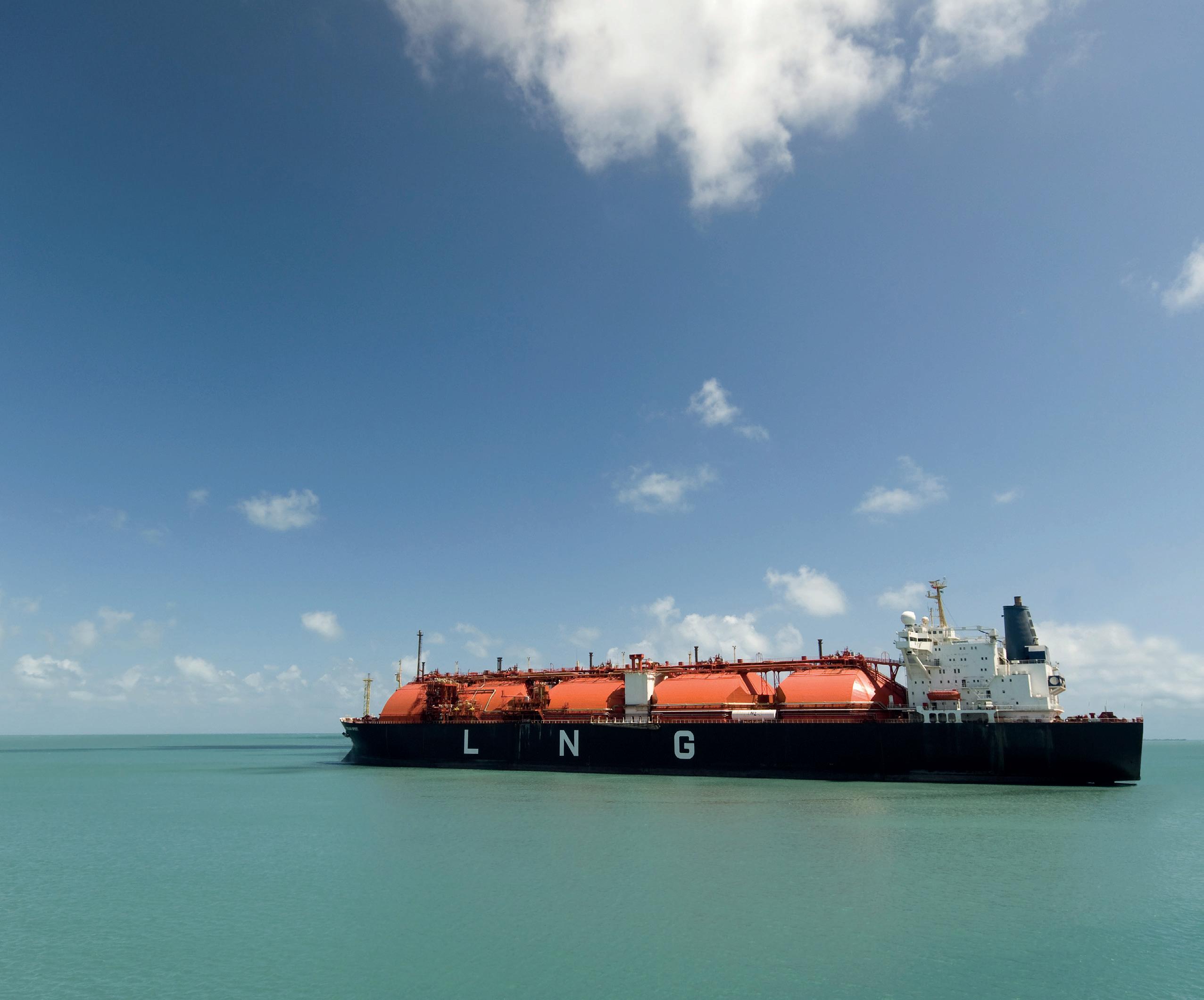


LNG Industry magazine Register for your free subscription at: www.lngindustry.com Global coverage of the entire LNG value chain
require full separation between cargo handling of BOG and fuel for propulsion. This can be done by installing full reliquefaction on deck, including a dedicated LNG fuel tank where the bio-LNG/e-LNG used as fuel can be stored.
CII reporting
When specifically considering the requirement to report CII data by LNG carriers already in operation, reliance on gas will be even more important than it is today. Fall-back operation on fuel oil will give a carbon dioxide (CO2) penalty when CII data is reported.
A small number of LNG carriers feature newer two-stroke dual fuel engines and have implemented increased redundancy with gas use, though only one engine maker has introduced this to date. With a cylinder cut-out in gas fuel mode, the uptime on gas can be maintained, so such solutions will probably be implemented for other engine makers in the future.
Besides redundancy within the engine itself, there has been additional redundancy in the fuel supply system, especially LNG pumps, BOG compressors, gas sensors, and gas fuel filters, to secure an uninterrupted operation on gas. Over the last decades, this redundancy has seen full implementation in almost all new LNG carriers.
For the CII reporting, BOG burnt in the gas combustion unit will also need to be reported. If a failure happens in the gas system, the result will be that the engine system will fall back into fuel oil operation, resulting in higher volumes of BOG sent to the GCU and further increasing the CII carbon penalty.
For older LNG carriers which do not have the luxury of full redundancy, it will be a daily challenge to stay continuously in operation on gas. A well-trained crew with enough spare parts will be a must for keeping those ships within CII compliance.
Engine types
To help owners understand the impact of CII, ABS has created a compliance scenario based on the LNG carrier fleet equipped with steam turbines (Figure 1), equipped with dual fuel diesel electric (Figure 2), and equipped with two-stroke engines (Figure 3).
The CII prediction in Figure 1 shows that 100% of steam turbine vessels will have a hard time complying with the CII and will sit in category D and E in 2030. Steam LNG carriers – which represent one-third of the LNG fleet (27 m3 out of 86 m3 in total) are the least efficient of the ships operating in the gas fleet today. To become compliant with EEXI regulations, steam-powered LNG carriers will have to reduce their engine MCR by roughly 50% using a Shaft Power Limitation (SHaPoLi).
However, these ships already operate with approximately this power level. Therefore, applying SHaPoLi and reducing speed is not a practical solution, both due to the operational requirements of the LNG trade, but also due to the performance of the steam plant, which becomes very inefficient at reduced power/speed levels.
The EEXI regulations as proposed cannot be met as steam vessels do not operate the same way as the diesel vessels (for which the main concepts of EEXI have been developed) and there is no simple technical fix that can change them to make them compliant.
To do so would require major changes to those ships, requiring either:
� Carbon capture: at present, there is no proven technology for marine applications available and no ports are equipped to receive CO2. There are carbon pre-capture technology options, that turns CO2 into solid carbon, which might be easier to handle in port. It will, however, require that hydrogen can be blended into gas and burned in the steam boiler. The expectation is that this is technically feasible, but it will require testing to verify it.
� Installation of reliquefaction systems: this may help in managing BOG, but it will take energy to run and will not improve the overall fuel efficiency of the steam plant or reduce emissions. But this solution could be combined with the use of either ammonia or hydrogen blended into the gas going to the boilers.
� Re-engine to convert to a dual fuel diesel vessel: this would, however, cost double digit millions and is not foreseen as an economic solution. Adding a single two-stroke dual fuel engine seems to be the cheapest of the options, but it is a bigger conversion, and it is not without financial and technical risk to complete such a project.
Some 40% of dual-fuel diesel electric LNG carriers (Figure 2) will be in category D and E by 2030. These ships constitute a little less than one-third of the LNG carrier fleet, and what is evident from the reporting is that many operate on fuel oil during the ballast voyage leg.
Achieving a better CII rating will require the amount of gas used to be maximised. If this does not have enough effect, DFDE carriers will also need to reduce speed during the ballast leg to save fuel. Reducing speed during the laden leg is not practical as DFDE carriers already operate solely on BOG and a reliquefaction system is typically not installed on those ships.
If they reduce speed further, the BOG will instead have to be burned in the GCU, so lowering the speed will have the opposite effect, in that more carbon will be emitted.
Four-stroke engines burn natural gas using the Otto cycle, and they have relative high methane slip levels that most likely will be penalised in the CII. Methane oxidation catalysts designed to reduce methane slip from the exhaust gases are under development from several manufacturers, and it is possible that such a system will be available and possible to retrofit.
Some 25% of LNG carriers equipped with two-stroke engines (Figure 3) will be in category D and E in 2030. These LNG carriers are the latest standard, and while they are the most efficient of the three segments, they constitute a little more than one-third of the fleet – though this share is growing rapidly.
Many of those ships are equipped with full reliquefaction, which means it is possible for them to reduce speed without burning additional BOG in the GCU. Many of them are operating on fuel oil instead of gas, so improving the CII rating becomes easy as most are dual fuel, so they can simply just switch to natural gas. Many of the two-stroke engines burn natural gas using the Otto cycle so also suffer from relatively high methane slip levels that most likely will be penalised by the CII.
38 October 2022
he number of LNG-fuelled vessels entering into operation in the next few years is exponential as operators turn to LNG to reduce the environmentally and climate-harmful emissions. Typically cheaper than fuel-oil, LNG prices are high right now, but when the LNG-vs-fuel-oil market returns to normal, demand for LNG to fuel merchant vessels will follow.
The final price for LNG as fuel delivered on board has a surcharge that originates from the ‘last-mile’ delivery cost, meaning the cost from using LNG tanker trucks or LNG bunker vessels (LBVs).

Whilst LNG truck-to-ship activities will still be available going forward, LNG sea-based deliveries will eventually dominate the supply for merchant LNG-fuelled vessels.
And as demand for LNG grows, the required infrastructure will follow.
Schulte Group has used its experience as an LNG bunker vessel owner and operator to design the next generation LBV which will fulfil present and future demand and reduce last-mile costs.
The LNG industry has an enviable and robust safety record, and the pioneers of LNG bunkering created the technical designs for the LNG fuelling and service
vessels currently in service. These vessels continue to be successful, and will be in operation for the foreseeable future.
When Schulte Group examined the market’s current requirements, however, the company recognised the need for a straightforward LNG fuelling ‘work horse’ that reduces the cost of last-mile delivery for vessel operators. Schulte Group has gone back to the drawing board and defined the operational requirements and corresponding specifications of what the ideal LBV should offer, doing away with any additional or unnecessary gear and cumbersome operations.
Schulte Group has therefore developed an inherently safe design for an LBV, with an intuitive human/machine interface that is easy to handle and operate and straightforward to understand.
Key features include an outrigger system that works with any vessel type, gas freeing and aeration equipment to prepare LNG-fuelled vessels for drydock, and flexible design options so that the LBV can be tailored to requirements. The vessel can also be operated by a smaller crew whilst still enabling high safety levels.
All of these components are geared towards reducing the CAPEX and OPEX costs for owners and operators,
Johan Lillieskold, Gas Solutions Specialist, Schulte Group, Germany, examines how LNG bunker vessels can reduce last-mile costs for ship operators.
39
and, ultimately, will achieve low last-mile costs for the LNG-fuel industry, including the LNG-fuelled client vessels.
Compatibility
One example of how this design can favourably affect the OPEX of a client vessel’s (or LNG-fuelled vessel’s) operations is the innovative outrigger system that can accommodate any vessel type.

Usually, the rigging of fenders on board a seagoing LBV takes 1 – 2 hrs with the engagement of a substantial deck crew. Schulte Group’s LBV does away with the use of a spacer pontoon, and avoids manually shifting, deploying, and mooring the typically heavy inflatable fenders alongside the LBV. With the outrigger system, it takes approximately 5 mins. with the single push of a button. Furthermore, due to the increased distance between the vessels, the more favourable, less steep angles achieved with the mooring ropes to a client vessel with high freeboard results in safer and easier moorings.
Schulte Group’s LBV work horse has been designed to maximise compatibility with existing and known future LNG-fuelled tonnage, including:
� Vessels with protruding structures from the hull, such as those typically found on cruise liners with protruding lifeboats, deck structure, and balconies (see Figure 2). One solution is the outrigger and fendering system, which is safe and fast to deploy.

� Vessels with short, usable parallel bodies, for example, large, high-speed, slender container vessels with bunker ports located forward or aft. For this type of vessel, the LBV’s forward manifold will provide reach into or up to bunker stations.
� Vessels with high freeboard, for example, very large crude carriers (VLCCs), large bulkers, large container vessels, large heavy lift vessels as semi-submersible crane vessels. The LBV’s long-reaching telescopic crane extends over 40 m over the water. It is compatible with all known and soon-to-come LNG-fuelled vessels.
� Vessels with bunker stations located low down, for example, some cruise liners, Ro-Pax, and some container vessels. Such vessels can have bunker ports situated as low as 3 m above water line. This causes challenges if the LBV has a large, fixed-reaching crane. A large crane can still be compatible but usually slows operations when safely transferring the LNG transfer system to a client vessel. The telescopic crane on the company’s LBV can be adjusted to any required reach. Consequently, the manoeuvring of the LNG transfer system (hoses, release couplings, quick connectors, and release system) can be undertaken faster, smoother, and in a more accurate and safe manner.
Figure 1. The LBV’s patented outrigger fendering system deployed.
� Vessels with bunker manifolds located extremely forward or aft of the ship’s length. The LBV’s forward manifold will ensure compatibility with this type of vessel and still maintain a safe mooring pattern.
� Large scale LNG terminals with loading arms typically located 14 – 16 m above water. The LBV can be equipped with a high manifold, making the vessel compatible with large scale loading arms. This can be advantageous in areas where an operator is a ‘first mover’, where no other means of loading an LBV is available. Regardless, if the LBV was not initially fitted with a high manifold, the vessel is similarly prepared, with scantling, stability, routing of piping, penetrations, for example, all incorporated into the design. A high manifold can be fitted later with limited modification and incurred off-hire time.
Scaleable design
Schulte Group has designed the LBV with a series of selectable options, so that it can be tailored to requirements. Operators can choose from the following:
� Outrigger vs normal Yokohama type fendering system.
Figure 2. The LBV alongside a cruise ship, looking towards the hull, with lifeboat protruding. The deployed outrigger system keeps the LBV a safe distance from the ship without the need for pontoons. The dashed U-shaped line to the right represents the safety boundaries around the valves/gas mast, with port side mast in use.
� Sub-cooler vs no sub-cooler.
� High manifold vs no high manifold.
� Forward manifold vs no forward manifold.
� Battery hybrid vs no battery hybrid.
40 October 2022
� Cargo tanks 304L (ammonia ready) vs 9% nickel steel (LNG only).
Reduced OPEX


Schulte Group’s new LBV has been designed and built with the crew, work space, and the human/machine interface in mind. This, for example, applies to the trunk deck covering cargo lines, cabling, and instruments. Not only does this reduce OPEX through reduced maintenance, but, equally importantly, it serves as the LNG transfer system preparation and maintenance workshop deck. Further, the company has introduced mooring stations with a clean design that is safe to work and easy to maintain.
When this design is applied, the crew required to operate and maintain the vessel can be reduced, and consequently so is the OPEX and the last-mile surcharge for the LNG fuel.
Drydock background and challenges

Many more LNG-fuelled vessels are scheduled to enter the market in the next few years, and this in turn will increase the number of LNG-fuelled vessels requiring repair and routine drydocking.
Depending on the type of the LNG-fuelled vessel’s fuel gas tanks and/or required repairs, in most cases, the fuel gas tanks are required to be liquid freed and, at least inerted, if not aerated (gas free), prior to entering a repair site or dockyard.
There will further be occasions where LNG-fuelled vessels are required to undergo unplanned repairs, often on a commercially urgent basis to avoid off-hire.
Typical examples are after a hard steel frame indent from a tugboat, or a berthing incident requiring small to semi-major hot work.
At present, LNG-fuelled vessels and LBVs are dependent on external service providers to support all operations to condition a cold and gassed up LNG tank to become a warm aerated gas-freed tank that can safely enter a repair site or drydock.

Further, it is unacceptable, and will become increasingly less acceptable, to vent methane (CH4) to the atmosphere, other than in emergency situations, and LNG-fuelled vessels are almost never equipped with onboard gear to handle CH4 and burn the same during a gas freeing operation. Nor are they equipped with large capacity inert gas plants to handle inerting of own fuel tanks or aeration fans for aeration (final gas freeing).
As such, gas-freeing operations today are quite cumbersome and time consuming. The LNG-fuelled vessel or LBV needs to find a berth or terminal where such an operation is allowed and possible. After which, if the operation uses gear supplied solely from the shoreside, a large amount of different gears will be required, as well as portable hot flare/gas combustion unit (GCU), propane tanks, liquid nitrogen tank(s) and/or trucks, vaporisers, heaters, and cryogenic hoses. Not forgetting the considerable time required for co-ordination, authority permits, and planning.
It is against this background that Schulte Group set about developing an LNG tank conditioning system and including it within the company’s LBV work horse design.
Advanced Asset Condition Monitoring and Analytics in the LNG Industry Using a Historian-Based Solution


After more than 20 years in the LNG industry, Brüel & Kjær Vibro has built a solid foundation in condition monitoring, diagnostics technology and services, and we want to share that with you.


The data management portion of our solution is vital to this industry, and we strive to deliver transparent, non-proprietary data to other systems and historians such as OSIsoft® PI System® All relevant users can now have unhindered, cyber-safe access to raw data, historical data, and PI-based analytics. This dramatically improves the reliability and speed of making operation and maintenance decisions. Contact us to find out how our comprehensive, non-proprietary monitoring solution can benefit you.
Scan the Code to Learn More

BKV-software-halfpage-ad.pdf 1 9/26/22 7:38 AM
Drydocking solutions
The solution to the above challenges and the key characteristics of the company’s conditioning system are:
� High warming-up capacity through the circulation of hot CH4 from LBV to the LNG-fuelled vessel, i.e. the cold vapour return from the LNG-fuelled vessel will be re-heated and sent back to the vessel’s tanks. As and when the tanks warm up and gas expands, it is combusted in the LBV’s high-capacity GCU.
� When tanks are warmed-up, the LBV produces and sends dry nitrogen (N2) inert gas to the LNG-fuelled vessels tanks and returns increasingly N2-rich vapour. This vapour return is efficiently and sustainably combusted in the LBV’s GCU, regardless of its N2 content.
� When the tanks are fully inerted, aeration of the same is undertaken by the LBV by supplying clean dry air to the tanks.
All capacities and operation flows are designed to reach above-ambient temperatures in order to allow technical best practice and safe entrance to the tanks on aeration completion. The best calculations for a 6700 m3 tank demonstrate that Schulte Group’s new LBV can carry out this full operation – from cold tanks with CH4 to gas-freed, ready-to-enter tanks, or obtain gas a free certificate to enter a repair site, within 5 – 8 days.
The warm-up operation of the same tank would normally take 20 days without the support from the company’s LBV’s conditioning system. Add to that inerting and aeration, the full operation would take an estimated 25 – 30 days, without accounting for deviation to a suitable berth to undertake a similar operation supported from ashore.
Schulte Group’s conditioning system reduces LNG-fuelled vessels’ off-hire periods and avoids the time and cost of finding a suitable LNG terminal or berth where the above outlined operation can be environmentally and safely undertaken.
LBV mooring operations
LBV vessels are expected to undertake numerous mooring operations each day. Therefore, Schulte Group has invested
The Schulte Group LBV
Key features:
� Outrigger system that enables bunker operation with any type of LNG-fuelled vessel, including cruise ships. The unique patented design does away with spacer pontoons and inflatable fenders. The outrigger system can be launched in approximately 5 mins. by the push of a button.
� Flexible design options so that they can be tailored to requirements to ensure minimal CAPEX.
� Smaller crew complement whilst still maintaining high safety levels made possible through an intuitive human/machine interface and rationalised deck based on best practice operations for safe and easy mooring operations.
� Gas freeing and aeration equipment to prepare any LNG-fuelled client vessels for drydock.
particularly in designing effective and safe mooring stations, and incorporated experience and know-how from over 100 Optimoor studies into the mooring station design of the company’s new vessels.
The LBV workh horse is therefore equipped with a sufficient number of mooring stations and mooring drums, all of which are clear of other deck gear and equipment that could interfere with safe and efficient operations.
The forward mooring station is semi enclosed – with windlasses located on a different deck – hence nicely protected from weather, clean, and roomy.
Further, logical features such as free sight of mooring ropes during operations has been designed into the mooring decks and stations. This makes operations safe and at the same time reduces manning to the minimum without being unsafe.
These accumulated factors enable the LBV to be compatible with any LNG-fuelled vessel, to facilitate fast, safe, and efficient mooring operations, meaning more bunkers can be delivered overall per day.
Eco-sustainability
Schulte Group’s LBV has been developed in accordance with the International Code for Safety for Ships Using Gases or other Low-Flashpoint Fuels (IGC) Code and other International Maritime Organization (IMO) regulations. It is also required to comply with new and future decarbonising incentivising rules and regulations, among those IMO’s Carbon Intensity Index (CII) and the EU’s Fit-for-55 programmes.
The better prepared the vessel is to tackle any decarbonisation requirements, the more likely its residual value will be maintained.
Measures built into the design and available for future upgrade:
�
The battery hybrid solution saves energy and reduces carbon emissions, delivering an initial good Energy Efficiency Design Index (EEDI) and CII rating.
� The battery hybrid solution allows normal LNG-fuelling operations (bunkering) to be undertaken using battery power only with zero carbon emissions. Moreover, it reduces noise-pollution – important where noise can impact bunker permit applications.
� The hull has been designed to increase tonnage mile efficiency. Even if an LBV is normally not required for extensive sea voyages, the vessel has been built with a slender and efficient hull for good EEDI and CII ratings.
� The vessel has capabilities to be connected to shore power. In combination with the battery hybrid solution and ‘green’ shore power, depending on the operation profile, the vessel could operate largely carbon-emissions free.
� The basic design has even taken into consideration future retrofit for hydrogen power. Operation range will be limited if all operations are undertaken using hydrogen (H2), but 2 – 3 days of operation is feasible between H2 bunkering.
Overall, Schulte Group’s next generation LBV work horse brings safety, compatibility, eco-sustainability, easy inerting, and warm up for repair and maintenance, low CAPEX and OPEX, and a scaleable and future-proofed vessel design that will meet the needs of the burgeoning LNG-fuelled vessel fleet.
42 October 2022
ltrasonic gas detectors improve process safety with faster, more reliable detection of high-pressure natural gas leaks. Process and plant engineers tasked with improving the safety of natural gas industry production and distribution operations are today employing a variety of gas leak sensing technologies. Mapping engineers need to design gas detection systems to protect people, equipment, and facilities by increasing the probability of detection and alarming. The consequences of not detecting gas leaks early can be disastrous and, depending on when they are detected, will determine the outcome, as can be seen in the event tree in Figure 1.
The traditional sensor technologies for methane gas leak detection within the LNG industry are: catalytic bead and infrared (IR) point detectors, and either IR or laser-based open path

gas detectors. They are all well-known technologies with decades of proven performance in the field.
All of them have their unique advantages depending on the target gas, application, and environment. They also have their limitations, and to be able to detect the gas leak, they rely on the gas cloud migrating to the sensor. Due to a variety of reasons, these gas detectors may fail to detect a gas leak. This could be due to inadequate fire and gas mapping – either an insufficient quantity of sensors or their incorrect placement, the selection of gas detectors which are not fail-safe and when the sensor dies it does not go into fault, or the most likely scenario, which is the wind blows the gas away from the detector (Figure 2) or strong winds dilute the concentration below the alarm level. Truly dangerous pressurised gas leaks can be a challenge to detect
Andrzej Janowski, MSA Safety, Poland, outlines how ultrasonic gas leak detectors provide an additional layer of protection in LNG facilities, and how pairing this with artificial neural network technology can contribute towards more reliable detection of a gas leak.
43
reliably by anyone using any of the conventional catalytic bead, point IR, and open path gas sensing technologies. Although some gas leak releases make a jet-like noise, operators may not be nearby to hear the escaping gas. Given the challenges that conventional gas sensors face in detecting high-pressure gas releases in outdoor environments, it is not surprising that ultrasonic gas leak detectors (UGLDs) are becoming more widely specified. Along with the conventional gas detectors, UGLDs are being used as part of the new design concept, which incorporates ‘multiple layers of protection’. The optimal design for high-risk applications incorporates point, open path, and ultrasonic gas detectors.

UGLDs offer a number of advantages including immunity to gas dispersion from wind, which is a serious limitation with point and open path sensing solutions. Instead, UGLDs detect the gas release as soon as it starts by instantly hearing the sound the leak makes. As UGLDs do not have to wait for the gas cloud to reach the sensor and then reach a high enough concentration to activate the first alarm, this saves valuable time in alerting the control room of the gas leak. This could be a few seconds or a few minutes faster than conventional gas detectors, which in some cases may never detect the gas leak.
Ultrasonic leak detection in natural gas applications
UGLDs are used today on offshore platforms, onshore processing plants, and compressor and metering stations along pipelines, including various LNG facilities. Due to the nature of LNG and low storage pressure, UGLDs are recommended for installation at the point of regasification, within gas turbine skids and enclosures, and during the LNG liquefaction process where pressurised refrigerants are used.
They are highly effective in protecting compressor stations which carry essential tasks in the natural gas network after the regasification stage, as they transport greater volumes of the raw material from the LNG terminal to the domestic or commercial gas transmission network. Compressor stations are placed strategically within the gathering and transportation pipeline network to help maintain the pressure and flow of gas to end users. Their strategic importance for the correct functioning of the entire network requires the best safety solution for the early detection of dangerous compressed gas leaks.
Variable background noise problem
Being non-contact measurement devices, UGLDs protect against both combustible and toxic gas releases, and their detection
range can be verified by using inert gases with similar molecular weight and heat ratio as those of the gases of interest.
In ultrasonic gas detection, a sound wave is simply a pressure pulse in the air that is detected by the human ear the same way that it is detected by a microphone. The human ear can only perceive acoustic sound waves in the frequency range between 20 – 20 000 Hz (20 kHz), and that is why this frequency range is called the audible frequency range. Acoustic sound frequencies above 20 kHz are called ultrasound.
When pressurised methane is released through a leak, the hissing noise produced is called broadband acoustic noise, ranging from the audible frequency range into the ultrasonic frequency range. Earlier generations of UGLDs only ‘listened’ for the gas leak noise in the ultrasonic frequency range from approximately 25 kHz and above.
UGLDs measure the sound pressure produced by the escaping gas. As the sound pressure exceeds a pre-set level normally produced by background noise, the detector indicates an alarm condition. Such threshold-crossing devices essentially record deviations from baseline conditions early enough to detect dangerous leaks of pressurised gases and to initiate appropriate warnings.
Despite the advantages of threshold monitoring, the performance of today’s conventional ultrasonic gas leak detector depends on an assumption of a fixed background ultrasound level at a particular installation. Likewise, the alarm delay setting on such devices is based on a presumption of intermittent ultrasonic sources (false positives) that are fixed in duration. In any industrial environment, such background conditions may vary in terms of both magnitude and duration. Furthermore, as operators seek to avoid frequent changes to configured devices, pre-set sound pressure thresholds and alarm delays significantly limit the instruments’ detection range and speed of response.
Real gas leak detection
To overcome these limitations, more advanced UGLDs have been developed and incorporate artificial neural network (ANN) intelligence. This new UGLD design distinguishes the broadband ultrasound produced by pressurised gas releases from other artificial and natural sources. Such a design can be implemented with or without a threshold-crossing scheme, enhancing the scaleability of gas leak detection.
For convenience, the detector can operate with the threshold-crossing scheme or one of several enhanced modes that rely on ANN to classify ultrasound signals. Furthermore, testing results show that the UGLD with the ANN algorithm achieves a longer detection range (radius approximately 28 m) and a shorter response time in the presence of ultrasonic background noise.
An ANN operates in a manner very similar to how the human brain handles the constant flow of information. When meeting a person, the brain receives a massive amount of visual information through the eyes, and, over time, this substantial amount of information is used to recognise this person years later or even to identify further family members.
In other words, the more the brain is trained to recognise familiarity, the better a person will be able to recognise or deny another person’s face. The brain does not look for an exact match, it looks for familiarity, and so does the ANN.
44 October 2022
Figure 1. Gas release event tree.

ENERGY GL BAL Sign up to receive a digital copy of the magazine www.energyglobal.com/magazine The future is looking clean and green
Like the brain, however, the neural network needs to be trained first. The UGLD needs to be trained to recognise the sound signature from a gas leak effectively while at the same time rejecting sound signatures from acoustic background noises that are not related to gas leaks.
Acoustic noise from a real gas leak source normally ranges from 10 kHz and up to the 60 – 70 kHz range. Acoustic noise
from a false alarm source, such as a gas compressor for example, can easily generate high level frequencies in the range of 100 Hz – 20 kHz.
Earlier generations of UGLDs were designed with electronic filters to screen out and ignore noise below 20 kHz, which eliminated false alarms resulting from most normal plant background noise, such as gas compressors, but also limited detection of smaller real gas leaks.

New technology for gas leaks
The Observer® i UGLD (Figure 3) is the first device in its class equipped with ANN and real-time broadband GASSONIC acoustic sound processing technology. This technology is based on extensive studies and more than a decade of real recording of gas leak sounds and industrial background noise from a wide array of industry sources. The ANN algorithm has been factory trained with these recordings to automatically distinguish between unwanted acoustic background noise and dangerous gas leaks, as depicted in Figure 4.
With ANN technology, the Observer-i UGLD makes it possible to fully analyse the sound spectrum as low as 12 kHz by eliminating the use of common high pass filters. This advanced approach provides a broader leak detection range, which also increases sensitivity to smaller gas leaks without interference from unwanted background noise.


ANN technology allows the Observer-i UGLD to be installed without time consuming training sequences, and it provides good detection distance with unprecedented suppression of false alarms. In addition, ANN technology ensures that the Observer-i UGLD has the same gas leak detection coverage in high and low noise areas. The device requires no alarm set points or trigger levels to be configured, nor do these alarm parameters need to be adjusted if background ultrasound were to increase or decrease over time. ANN technology also adapts to new sounds should the plant install new equipment and does not require sound mapping engineers to return to the site to retrain the device.
The Observer-i UGLD also features the GASSONIC SenssonicTM self-test function. This well-proven self-test checks the device’s electrical integrity and microphone every 15 mins. and ensures the UGLD is operational at all times. The microphone and the microphone windscreen are constantly monitored to ensure that the detector always has optimal sensitivity and detection coverage.
Conclusion
LNG facility safety systems that deploy diverse, complimentary, early hazard detection technologies can counteract possible effects of leaks, fire, and explosions, preventing equipment or property damage, personal injury, and loss of life. Only relying on point or a combination of point and open path gas detectors is no longer recommended for high-pressure natural gas installations within the LNG value chain. UGLDs provide an additional layer of protection, giving faster, more reliable detection of a gas leak. Adding ANN intelligence capability to UGLDs provides process and plant engineers with a plug-and-play detector that requires no special training during installation, and it avoids nuisance false alarms. The Observer-i UGLD, with its capability to reliably detect leaks below 20 kHz, provides another layer of safety to the industry, protecting people, equipment, and facilities from hazardous methane gas leaks.
46 October 2022
Figure 3. The MSA’s Observer® i detects gas leak at the speed of sound.
Figure 4. Artificial neural network (ANN) technology distinguishes between background noise and gas leaks.
Figure 2. Conventional gas detectors require gas to reach the sensor before alerting of a gas leak, whereas UGLDs just need to ‘hear’ it.
NG producers see the same global market pressures as the rest of the world’s industries. The pandemic caused lockdowns of economies worldwide, energy demand crashed, gas prices plummeted, and LNG demand tanked. Emerging from the COVID-19 crisis, LNG supply fundamentals looked encouraging as markets, particularly in Asia, continued to expand. LNG demand increased when the Russian invasion of Ukraine created energy shortages, causing soaring oil and gas prices. Given such a backdrop, LNG futures look attractive. Nevertheless, the industry cannot escape the technology forces shaping other manufacturing production industries.
The drivers of the undercurrents that today affect LNG and other industries began 11 August 2011, when Mark Andreesen, Founder of Netscape and Grandfather of the Internet Browser, published an article in the Wall Street Journal where he stated: “Software is Eating the World!” Quite an esoteric proclamation, but his projection was a harbinger of things to come where great efficiency and profitability would be derived from software and its decedents: digitalisation, data management, big data, artificial intelligence (AI), and machine learning (ML). Such are the software artifacts that propel the new applications that are shaping the consumer world in social media, the online buying experience, media streaming, automotive technology, location services, Mike Brooks, Aspen Technology, UK, describes how software and data management drive efficiency in the LNG industry.

47
and so on. But such software technologies are also propelling great advances in manufacturing software and data management that drive compelling applications.
Solving real problems
However, it is strategically important to understand that applications that do work on data solve the real problems, and the aforementioned software technologies provide only a supporting role. In the zeal and excitement over the new software and data management tools, the imperative must be to keep focus on the business problem to be solved – do not lose sight of the fact that technology is a potential enabler but not the solution. Clearly, the leading-edge applications in industry, including LNG, focus on analytics, especially rote, repetitive, high-frequency analytics over multiple dimensions that escape human capability.
Then, when the analytics have uncovered issues, humans can intervene to do what they do best in affording judgement and making decisions. The complete solution is a combination human-machine approach. However, to afford success, it is most important to identify the business problem, its explicit data requirements, and to carefully select the appropriate applications that directly align with the analytics job that will enable the business outcome. For example, some companies focus and invest heavily on building a data lake. A data lake is not a strategy: it might be a means to store the data, but it is not the only one. The strategy will be the right application to ensure the correct business outcome. That strategy will require the correct business data context for the solution; the data cannot just be stirred and algorithms applied and get meaningful solutions. This means that analytics work must align with important business goals. And today, a further pre-requisite insists the organisation develops a proper analytical aptitude that is factual and data-driven rather than opinion-driven. Truth comes from data which does not have opinions.
To reinforce this position, consider that the foregoing digitalisation, data management, big data, AI, and ML software and data management technology constructs are bandied around as initiatives. They are not; they are only the potential tools to support and enable an initiative. In the past, a focus on the software technology instead of the real initiatives caused many projects to fail, such as data warehouses. This showed that it was necessary to know what to do with the enablers before they were built. It was also necessary to lead your initiatives with a real business problem. That begs the question: what are the real initiatives in LNG where such technology constructs are the supporting cast? Real operational
performance initiatives begin from high-level business drivers, such as:
z Keeping the equipment running, as to avoid downtime and poor performance.
z Ensuring the lowest use of energy and other resources in making products.
z
Achieving optimal yield and quality of high-value products.
z Optimising the cost and risk of all asset expenditures over their life-cycles.
The previous four are the highest-level key performance indicators (KPIs) for LNG and other manufacturing industries wherein deficiencies in each one will cause margin leakage, loss in profits, and can affect safety and the environment. Of these, keeping the equipment running and available to plan is by far the most critical since energy consumption, quality/yield, and cost/risk are inconsequential if the equipment is shut in.
Predictive Maintenance

Following Andreesen’s forecast, new software has emerged and is up to the maintaining equipment availability task. It goes by the general name of predictive maintenance (PdM), but not all entrants under the PdM banner contain predictions and can be trusted. An assertion is not the same as a prediction. However, the field of PdM has advanced so that the leaders in the market contain new technology capable of recognising the specific patterns of behaviour from sensors signals on and around the machines. They detect patterns of normal behaviour, and the outliers of abnormal behaviour, plus the explicit patterns of degradation that if not attended will lead to failure and non-operation. The best applications mean that the underlying technology is easy-to-use because the engineering technology and data science are abstracted, allowing current personnel to develop complex detection strategies. Inside, the technology performs explicit pattern recognition using unsupervised, supervised, and deep machine learning techniques across a myriad of sensor data stream dimensions and across time for explicit/accurate detection that limited capabilities prevent humans from seeing. Such is more accurate and much earlier pure pattern recognition and not simple engineering and statistical model trimming.
Transferable knowledge
The results provide warnings of impending events weeks and months in advance. Such advance warnings are critical for LNG operations since they provide the time to adjust the process to avoid an incident, or if necessary, the time to plan a safe orderly shutdown without emissions releases via the flare stack or pressure release valves. As an example, they prevent the damage in the first place where advanced warning can result in operators increasing cooling to avoid liquid entrainment into compressors and consequent compressor deterioration. The pinnacle PdM applications can also learn on one asset and do a one button click to transfer the learnings intact to other similar equipment. This represents extreme solution scaleability, since with little effort the software can detect normal and fault patterns automatically on new equipment. In this way, a pool of compressors or pumps are readily protected, and each piece of equipment shares its learnings with all the others, providing extreme blanket coverage. For example, analysis on an LNG train detected that it had compressor problems well in advance,
48 October 2022
Figure 1. Digitalisation supports and enables initiatives.
and the learnings were passed to a second train to detect the same issues there. In summary, extra time is money, and it also ensures safer and cleaner outcomes.
Additional software applications are readily available to monitor LNG energy usage, some with great sophistication to ensure the least energy input will provide the heat to secure hydrocarbon product separation at the lowest cost. A critically important application with enormous and rapid payback provides real-time optimisation of operational activities to ensure the maximum yield of product at the lowest cost. Additionally, digital applications transform LNG plant scheduling and longer-term planning activities with sophisticated supply chain analytics. Decision support digital applications provide both offline decision support tools wherein digital models (now called digital twins) can try out myriad ways of controlling operations in a safe, digital-only environment. Such models may be transformed into closed-loop operations that automatically adjust parameters and setpoints in the distributed control system and also project probabilities of future plant conditions.
Detecting latent variables
Addressing quality control with computer-based applications for petroleum-based industries has been around for decades, including sophisticated computer models of process behaviour and special constructs such as management by statistical process control. However, novel quality and yield applications have emerged and are readily available for LNG operations that perform intense computational analysis using hybrid models amalgamating first principles equations with AI and advanced statistical modelling. Such applications will examine months or even years of past data history to uncover the real-life performance and detect latent variables – combinations of measured variables that are far more accurate in measuring and predicting changes in process conditions. They detect the intrinsic cause of process deviations that make quality and yield go awry and offer prescriptive advice on what to adjust to get back on track to maintain the correct quality consistent with the highest yield.
Another key aspect in managing an LNG operation is to ensure that financial expenses on the process and the equipment provide the optimal lifetime return on assets. There are intensely computational applications that can examine all benefits and risks in operational eventualities that can influence LNG production, such as equipment redundancy effects, flow bypasses for heat integration and process control, other alternative operational strategies, and the availability of intermediate storage. The leading applications can understand and advise on other issues inducing risks to profitability, including changing demand, unit turn-up capability, weather and supply/delivery logistics, spare parts inventory, and the quality of service and repair. For full and efficient LNG train operation, the planners need first-rate understanding well in advance to implement the appropriate tactics and longer-term strategies at the appropriate risk and costs. Such a digital analytics application is critically important in understanding and planning ongoing OPEX and budget allocations in addition to CAPEX for major extensions or new projects.
Clearly, as Andreesen said, software is eating the world and is available to play a huge part in keeping LNG facilities safe, environmentally-friendly, and at the peak of efficient production and profitability.
REMBE® Your Specialist for Pressure Relief Solutions. © REMBE® | All rights reserved rembe.com hello@rembe.com
orced outages are one of industrial process facilities’ most significant pain points. As per a study by Deloitte, unplanned outages cost industrial complexes an estimated US$50 billion/y.1 Over the past several years, there has been much buzz around terms such as Industrial Internet of Things (IIoT), Industrial 4.0, digitalisation, artificial intelligence (AI), machine learning (ML), and predictive analytics as the next big thing in heavy industrial sectors such as oil and gas. The narrative surrounding these buzzwords is the promise that the mentioned technologies can predict when and how a particular piece of equipment will fail. The term ‘predictive’ is often misused and even misunderstood for technologies that do not deliver predictive capabilities. Hence, it becomes very critical to separate truly predictive technologies from non-predictive technologies and look at what is realistically achievable with large industrial equipment. This article discusses digital services as a maintenance component by considering a critical piece of an all-electric LNG complex: the medium voltage (MV) variable frequency drive (VFD).
Turning forced outages into unplanned outages

For any large facility, the compressor, pump, or other rotating equipment is at the heart of the system, moving gas, liquids, or materials from one process to another. Electric motors and VFDs provide a viable path to electrify and decarbonise energy-intensive processes. Figure 1 illustrates an electric motor-driven system on a compressor. The benefits of a VFD and its related energy savings impact have been very well understood, as shown through the discussion held by Verma and Phares at the 2022 IEEE IAS/PCA Cement conference.2 One of the concerns that end users and equipment operators have raised over the
years around a VFD-based system is what is the best way to maintain this equipment. Site personnel are seldom familiar with MV VFDs. While following the manufacturer’s instructions and maintenance schedule is a good start, it leads to either over-maintenance or under-maintenance since the required frequency and extent of care depend on the equipment operation and installation environment.
Condition-based monitoring (CBM) combined with human expert-level analysis answers the concerns raised by equipment operators. CBM is a requirement for any proactive-based maintenance. Any monitoring or digital service aims to convert forced/unplanned outages into planned outages. Industry participants have a significant misconception that AI, big data, and digitalisation will predict impending equipment faults and failures and relieve the burden of off-site maintenance. Predicting impending failures in the context of an MV VFD is extremely difficult to detect with a high-confidence level. It is not to say that predicting failure in the future is impossible. The current technologies and the market’s willingness to pay for such a solution are yet to be determined. Hence, it is far more effective to focus on proactively maintaining the VFD and reduce the mean time to repair (MTTR) so that when a failure or fault occurs, the operator or the manufacturer can quickly bring the VFD equipment online. All VFDs need maintenance, and some VFDs will trip when it is least expected. Unexpected downtime is the reality of any piece of heavy equipment. However, digital services can minimise the duration of downtime. The question then becomes what engagement levels are necessary with the VFD when it trips and goes offline.
Figure 2 provides an overview of five levels of engagement that a VFD might encounter.
Manish Verma, TMEIC, USA, looks at how digital services can avoid forced outages by turning them into unplanned outages and carve a sustainable path for medium voltage variable frequency drive maintenance.
50
As shown in Figure 2, most VFD issues are fixed by resetting the VFD fault. Resetting VFD after a fault is level 1 engagement. However, there are specific faults that require deeper evaluation on its cause – these are level 2 faults. Experienced site personnel familiar with the VFD equipment can work through the issue and bring the VFD back in service. However, a site that does not have access to in-house experts must depend on the manufacturer. The question now is how soon the fault is resolvable. Figure 3 illustrates how the response plays out in the absence and presence of a digital service engagement.
As shown in Figure 2, under a typical scenario, the VFD would detect a fault and then trip depending on the criticality of the fault. Since a simple reset did not fix the issue, further evaluation of the fault becomes necessary. The operator often has to contact the VFD manufacturer’s 24/7/365 service line to get support. While the manufacturer attempts to help the customer, the reaction time is not guaranteed since the equipment manufacturer has no connectivity, historical data, and rules of remote web engagement with the client and thus the VFD. Hence, the manufacturer and the equipment operator have to get on the phone and guide the customer to get the fault data off the VFD and then e-mail the settings and fault file. A field tech is often sent out to the site to troubleshoot the issue. This could take several hours or even days if a service tech needs to be dispatched.
However, with a digital services package purchased with the VFD; the fault detection, notification, historical context machine-generated data, and the rules of remote engagement are already available and established between the manufacturer and the site. This materially reduces the time it takes to troubleshoot the VFD and get it back in service. There are a multitude of ways in which digital services are packaged with the original equipment. However, in most cases, VFD operators are looking at a yearly subscription service for monitoring, reporting, notification, and human expert service. Here is a deeper look at the significant components of a typical proactive digital service offering:
z Component 1: Getting the data: This is an essential element of a digital service.There must be a way to capture, log, store, and trend machine-generated data over long periods

with sufficient resolution. A VFD is a piece of digital native equipment that generates a large amount of data that needs to be captured and analysed for later use. VFD manufacturers typically capture this in their provided software, which can pull in data by the VFD and publish it to a data historian. The captured data provides context surrounding a fault or a warning. The data-capture software is usually installed on a client-provided dedicated computer that can ‘see’ the VFD on the network. A virtual machine is also acceptable for this purpose. It must be noted that depending on the industry, there are strict requirements around data leaving the facility. Hence, a proactive digital service must be able to operate inside the ‘fence-line’ in the absence of an external network connection and allow access only when necessary.
z Component 2: Automated notification: The notifications include a high-speed data trace save of variables such as voltage, current, speed, DC bus, speed reference, and others right before and after a fault. This helps in diagnosing what external or internal event might have led to the fault in the first place. Also, during the operation, the VFD generates alarms and is notified via e-mail to a client’s chosen e-mail address. The capability is helpful since it keeps a historical log of all the faults and warnings ever since the digital package was activated and put in service on the VFD.
z Component 3: Expert-level human service: Until the artifical intelligence (AI) algorithms are sophisticated enough, experts with deep domain knowledge are critical. It is usually a service technician or an engineer from the VFD manufacturer itself. The expert usually engages with the VFD remotely for an hour or two monthly to review the fault and alarm notifications that might have occurred during the month and trend critical VFD variables that are leading indicators of VFD failure. This is the only time the end user must provide an outside web connection for the duration of the engagement. It is not necessary to stop the VFD during this time. The end user is provided with a report at the end of the engagement. The report outlines what the expert observed, any unusual
51
trends in the data that might indicate a failure down the road, and an assessment of onsite preventative maintenance service and renewal parts that might be necessary. The monthly report is useful for budgeting maintenance spend for the VFD under observation.
One of the significant benefits of a three-part service offering is that rather than running the equipment till failure, a more proactive-based approach can be taken and frees up the time of the site maintenance person to do other things. Further, should a VFD experience downtime, any trained professional, whether in-house or from the manufacturer, has immediate access to contextual data surrounding the fault. One can log into the digital service that hosts historical data, does an evaluation, and guides the site personnel. In most cases, the VFD is back in


service in a relatively short time compared to a VFD that does not have digital service components. Hence, a digital service offering from the manufacturer effectively reduces the MTTR. Figure 3 shows the typical network connectivity illustration.


Cyber security
When digital service or remote access type solutions are brought up in internal discussions, the starting position is almost always “it will be difficult to get past the IT department.” The concern is understandable in light of the increased cyber attacks on critical industries. The good news about the implementation of proactive digital services mentioned above is that for the day-to-day data capture, analysis, fault, and warning notifications, there is absolutely no need for remote access to the operational network. Only when the monthly engagement session is initiated is outbound connectivity from the computer hosting the original equipment manufacturer (OEM)-supplied software to an approved client necessary. Further, the time and duration of access are co-ordinated 2 – 3 days before the engagement. The pre-engagement step ensures access is provided only to the authorised service tech and only for the duration necessary to do a monthly VFD health check. Often, end users choose to screen record the actions the VFD manufacturer took for audit and record-keeping purposes.
Figure
Figure
Conclusions
Industrial facilities are starting to see the value in digital services. As mentioned, most digital services aim to have maximum equipment availability, reduce downtime, and maximise production. The global market sets the price of crude oil or natural gas. Hence, plant efficiency and production uptime can mean the difference between profitability and loss of a petrochemical facility such as a refinery, LNG facility, and others. MV VFDs in the range of a few thousand hp to tens of thousands of hp are used on critical services such as pumps, compressors, fans, extruders, and others. Their availability and reliability are critical to plant operations. Digital services provide a sustainable path to maintaining electrical equipment.
Further, the recent COVID-19 pandemic spotlighted the need for digital services for industrial equipment’s safety, reliability, and maintainability while preserving health. As a large part of the experienced workforce retires, there is increasing pressure on companies around how to replace the decades of equipment and process knowledge. Hence, the operators are increasingly dependent on the OEM to maintain their equipment, provide timely guidance on upcoming maintenance issues, and keep the equipment available. Proactive-based digital services have become accepted where the OEM can look over a plant maintenance personnel’s shoulders and track the equipment’s health and status.
References
1. COLEMAN, C., DAMODARAN, S., CHANDRAMOULI, M., and DEUEL, E., ‘ Making maintenance smarter’, DeloitteUniversityPress, (2017), www2.deloitte. com/us/en/insights/focus/industry-4-0/usingpredictive-technologies-for-asset-maintenance. html, (Accessed on 30/07/22).
2. VERMA, M., and PHARES, D., ‘Reaching environmental, sustainable & governance (ESG) goals with Medium Voltage (MV) Variable Frequency Drives (VFD)’, 2022 IEEE IAS/PCA Cement Conference
52 October 2022
Figure 3. Typical response timeline for variable frequency drive trips under digital and non-digital service scenarios.
2. Levels of engagement for standard variable frequency drive equipment.
1. Simple illustration of variable frequency drive electric motor. Figure 4. Typical network connectivity illustration.
s world leaders from 197 nations were negotiating what the result would be in the Glasgow Climate Pact at COP26 in December 2021, sea levels, ocean temperatures, greenhouse gas (GHG) emissions, and ocean acidification were all at their highest in history. Representative countries started developing and implementing lower-carbon energy systems in pursuit of net zero emissions.
In identifying and sourcing cleaner forms of gas for decarbonisation measures, LNG has taken a position as a

reliable and flexible energy source for now – and for decades to come. Demand is soaring globally. It is expected to double by 2040, hitting 700 million tpy or more – a 90% increase over 2021 demand.
With concerns over air quality, Asia is expected to consume a majority of the increased product as domestic gas production declines, regional economies grow, and LNG replaces higher-emissions energy sources.
As countries work to progress toward carbon emissions targets, LNG will also play a pivotal role in furthering
Cyndie Fredrick, Senior Vice President and General Manager of Merichem Process Technologies, USA, discusses the different pre-treatment options available for LNG, outlining the advantages of each.
53
renewable energy use and as a backup in the event of intermittent supply. In 2021, when Brazil experienced persistent dry weather which led to weaker hydropower generation, the country tripled its LNG imports to more than 7 million t.
The overall market growth has sparked a wave of advancements in existing plants and the development of new natural gas liquefaction units. LNG is considered a clean fuel compared to other fossil fuels, but the natural gas found in reservoir deposits has impurities. There can be considerable amounts of light and heavier hydrocarbons and contaminating compounds of carbon dioxide (CO 2), nitrogen (N 2), mercury (Hg), helium (He), hydrogen sulfide (H 2S), and others. Part of the LNG production process is removing the contaminants from the natural gas to meet pipeline or finished quality standard specifications as a consumer fuel. Cleaning also enhances the heating value of the natural gas and avoids pipeline and equipment corrosion problems in the downstream liquefaction process.
LNG impurities
The feedstock to LNG production facilities is comprised primarily of methane but includes other component species as well, depending on its source. All feedstocks must be pre-treated to remove any impurities, including H 2S, CO 2, water (H 2O), mercury, and heavy hydrocarbons. The contaminants must be removed to prevent freezing at the low liquefaction temperatures. After treatment, the feedstock gas is liquified to produce the LNG. There are several processes out there for each step of the
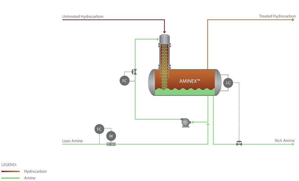
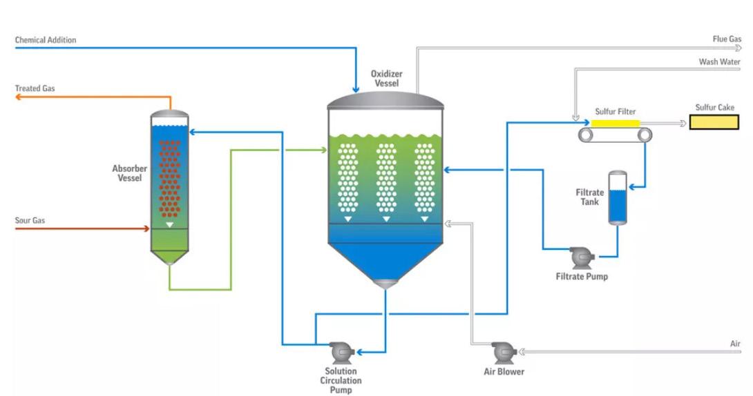
treating process. The following discussion will focus on acid gas removal (AGR) systems and options.
Treatment options for LNG feedstock
Amine treating
Typical AGR systems are comprised of an amine tower and regeneration system used to remove H 2S, carbonyl sulfide (COS), and CO 2, all acidic compounds, from the feed. In a typical AGR, amine contacts the source gas counter-currently in an amine absorber column and the acidic gas components are absorbed by the amine for treatment. The amine containing the acidic impurities is sent to a regeneration section to strip the impurities before the amine is circulated back to the absorber column to be used again. Depending on the unit and the feed impurities, these systems can work very well, or they may have significant issues including failure to remove all the impurities, amine losses, or foaming of the amine which can prove to be significant. In addition to those concerns, the challenge to remove COS or to prevent it from reforming in downstream sieve units is significant as COS can prove to be quite hazardous.
There are options in the market to help alleviate or remove some or all of these issues. These options can be designed into the system from the beginning or be added onto existing units to help improve performance. Merichem Company provides a solution using a FIBER FILM® Contactor (FFC), which acts as a mass transfer device to remove the acidic compounds. AMINEX TM technology, which uses an FFC provided by Merichem, can take the place of the amine absorber column. The benefit to using AMINEX in this system is that the contacting flow is less turbulent through the FFC, a vertical cylinder packed with proprietary metal fibres. The vertical, co-current flow and arrangement of fibres greatly reduces foaming and emulsion formation, decreasing amine carryover and ensuring the product gas meets specifications.
In an AMINEX, the amine phase flows along the fibres of the FFC as it preferentially wets them. Hydrocarbon flows through the amine-wetted fibre pack, where the acidic compounds are extracted into the amine phase. The two phases disengage in a small separator vessel. The treated hydrocarbon gas stream typically leaves the separator with minimal free amine due to the co-current Contactor’s non-dispersive combination of hydrocarbon and aqueous amine. Using the new FIBER FILM® Plus Contactor provides even more efficient performance, further reducing aqueous phase carryover and reducing the residence time required to achieve low carryover from the separator.
For clients with existing AGR’s that are experiencing foaming or carryover issues, an AMINEX treating stage can be installed just downstream of the absorber. Many companies recommend a separate water wash or other washing system to reduce problematic amine carryover, but Merichem’s AMINEX not only removes the pre-existing carryover and foaming, it also provides additional treatment to the hydrocarbon stream as an added benefit to the end user. The design can even be integrated in a small retrofit project to provide added throughput and
54 October 2022
Figure 2. Direct treatment process for hydrogen sulfide removal from sour gas streams. Figure 1. Acid gas/sour gas removal using amine.
tighter specifications if there is an existing water wash drum.
Caustic treating
As COS is a very challenging compound to remove from hydrocarbon streams, traditional amine treating is often not sufficient. In addition, if COS is not fully removed from the hydrocarbon stream, it can revert to H 2 S and CO 2 , potentially causing issues in downstream equipment such as mol sieves or building up H 2 S in downstream equipment, potentially causing other issues or providing a safety hazard.

Merichem Company has an additional solution for COS removal called AMINEX COS. If the amine in use is a primary or secondary amine, then this technology will lower the COS content. Alternately, a caustic wash stage with an added primary amine (known as THIOLEX TM COS) can also remove COS. THIOLEX COS also uses Merichem’s proprietary FFC as a contacting device, but the aqueous treating solution is caustic with a small addition of amine. The small amounts of COS typically present in LNG can easily be removed using this technology as a final treatment step. As an additional benefit of caustic washing, if the feed contains any residual amounts of mercaptan sulfur, H 2 S, or CO 2 , the THIOLEX system will also easily remove these acidic contaminants due to the much stronger alkalinity of caustic.
Amines will absorb methyl mercaptan to a limited extent. Heavy mercaptans are better removed by physical solvents that, unfortunately, also exhibit high hydrocarbon
co-absorption. This is generally not desirable for a solvent, particularly in hydrocarbon liquid treating applications, so caustic treatment is a much more attractive solution for removal of light mercaptans (methyl, ethyl, and propyl). For removal of low ppm of acid gases (polishing service), a THIOLEX system need not be paired with a caustic regeneration system since caustic consumption will be low. Furthermore, THIOLEX for gas phase treatment results in even higher mercaptan extraction efficiency than can be realised in liquid phase treating.
THIOLEX chemistry
COS(g) + H2O (l) → CO2 (g) + H2S (g)
NaOH + CO 2 (g) → NaHCO 3
NaOH + H 2 S (g) → NaHS + H 2 O (l)
RSH (g) + NaOH → NaSR + H 2 O (l)
Where R = C1, C2, C3.
Molecular sieves
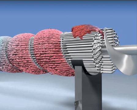

Molecular sieve adsorbents are zeolite-based compounds commonly used to remove water, carbon dioxide, hydrogen sulfide, mercaptans, and other sulfur compounds from the feedstock streams to very low outlet specifications.
Molecular sieves can dry the feed stream in addition to removing other contaminants. Their drawbacks are:
1. Significant capital investment.
2. Operating complexity.
3. Relatively high operating costs.
Additional treatment options for source LNG
There are additional options for treating the LNG feedstocks before they are pipelined to a collection facility. Before the gas can be sent to the collection facility, treatment of the gas must take place to meet the required pipeline specifications. Treatment units are built, including AGR’s, in those facilities to handle this task. Because the total H2S removed is significantly higher at the source, the acid gas stream in the regeneration system can have significant flows and is a concentrated source of H2S. There are good options for treating that acid gas, including the THIOLEX previously described, or if the stream is large enough, Merichem also offers its proprietary LO-CAT® technology.
LO-CAT is a desulfurisation technology for removing 1 – 20 tpd of H2S as sulfur from gas streams. The process chemistry of this technology is embedded in its name –LO-CAT stands for Liquid Oxidation CATalyst. The overall system oxidation reaction is as follows:
LO-CAT does not use any toxic chemicals and does not produce any hazardous waste by-products.
Another option to use LO-CAT would be to remove the H 2S upstream of the amine unit itself. This assumes there is a significant amount of H 2S in the untreated hydrocarbon gas as well as CO 2. If the H 2S is removed from the stream by the LO-CAT, the clean CO 2 can then be used for sequestration or other use.
Summary
The requirements and specifications involved in LNG production are stringent and often challenging to meet and maintain. By comparison, conventional natural gas plants can have more lenient product specifications, but the gas purity required for liquefaction of LNG is higher than that for sales gas.
This well-known reaction is sub-divided into two parts:
(i) H2S gas absorption, ionisation, and reaction to make solid sulfur in the liquid solution.
(ii) The liquid solution is then oxidised using air and regenerated for continued use.
In chemistry terms, step (i) is called reduction and step (ii) is called oxidation. Therefore, the LO-CAT process is called a redox (reduction-oxidation) reaction process.
Gas transmission companies recognise the need to have impurities removed to operate their pipelines efficiently and for proper use in end customers’ gas-burning equipment. Acid gas contaminants and mercaptans must be removed from a feed natural gas before it is liquefied. CO 2 is typically extracted to approximately 100 ppm to prevent freezing during LNG processing. Sulfur compounds are removed to levels required by the eventual end consumer. This makes the contaminant removal system an essential process design consideration for an LNG facility. Merichem offers many options for improvements on new or existing treatment facilities to ensure those specifications are being met. Some will provide additional advantages and should be reviewed closely when compared to simply using traditional options.
H2S (g) + ½ O2 (g) → H2O + So
ADINDEX www.lngindustry.com LNG Industry is audited by the Audit Bureau of Circulations (ABC). An audit certificate is available on request from our sales department. Advertiser Page ACME Cryogenics 21 AG&P IFC Air Products and Chemicals OBC Brüel & Kjær Vibro 41 Burckhardt Compression 02 Chart 09 Corban Energy Group 13 Energy Global 45 GAS and HEAT S.p.a OFC, 29 Advertiser Page GTT 25 Indra Srl 31 LNG Industry 37, IBC Nikkiso 07 Rembe GmbH 49 SIAD Macchine Impianti 04 Vanzetti 17 Watlow Plasmatech 55