
12 minute read
Hydrogen blending and LNG

Jeffery J. Baker and Randall W. Redman, CB&I, USA, detail how hydrogen can impact LNG peak shavers, outlining the solutions to keep LNG peak shavers operational.
here is a growing demand across the energy industry to reduce greenhouse gas (GHG) emissions, prompting governments, utilities, and consumers to seek out cleaner energy alternatives.1
Hydrogen is quickly gaining interest as a substitute for fossil fuels since its combustion produces only water with no carbon emissions. Green hydrogen is produced from water using an electrolyser with renewable electricity as the power source. Renewable electricity is often generated from solar, wind, hydropower, or even nuclear power, which is also considered a green power source.
One method to quickly integrate green hydrogen into the power grid is by displacing a percentage of natural gas in the existing natural gas distribution network with hydrogen. If the percentage of hydrogen is kept to an appropriate level, there is minimal impact to gas consumers. Utilising the existing gas infrastructure also provides a significant environmental benefit as it relates to construction requirements associated with implementation.
CB&I recently completed a green hydrogen production and pipeline injection project in Howell, New Jersey, the US. In that particular case, green hydrogen is produced from water, an electrolyser, and solar power. The hydrogen displaces a limited percentage of the natural gas in the gas distribution network, resulting in a cleaner hybrid fuel without significant impact to the operation of standard household gas appliances.
For now, these projects are limited to smaller, locally isolated networks, but as the concept is proven, more widespread hydrogen displacement into natural gas pipelines will occur with concentrations potentially as high as 20%.
Hydrogen impacts to LNG peak shavers
Though the limited presence of hydrogen in natural gas has minimal effects on residential appliances and
industrial burners, even a small percentage of hydrogen in the feed gas to LNG peak shaving facilities will affect the liquefaction process.
Hydrogen in natural gas will change the load on the liquefier and may even limit the liquefier’s production availability. Gas utilities need to be mindful of the impacts that hydrogen injection into the natural gas grid can have on their peak shaver liquefaction operation.
This report outlines the impacts caused by hydrogen in the feed gas and what facility modifications may be required if the natural gas feed contains hydrogen. When possible, it is highly recommended that hydrogen injection be located downstream of an LNG peak shaving facility to avoid issues with liquefaction. However, given the widespread interest in the hydrogen displacement concept, it is possible that hydrogen will become a common constituent in natural gas.
Typical composition of natural gas
A typical natural gas pipeline will have a composition similar to that shown in Table 1. A phase diagram for this composition is shown in Figure 1. A standard LNG peak shaver will liquefy the natural gas at pressures between 30 atm and 55 atm (440 psia and 800 psia). Figure 1 shows
Table 1. Typical natural gas composition
Component Mole fraction
Methane
Ethane
Propane
i-Butane
n-Butane
i-Pentane
n-Pentane
Nitrogen
Carbon dioxide 0.9381
0.024
0.0065
0.0005
0.0005
0.0002
0.0002
0.02
0.01

Figure 1. Phase diagram for natural gas.2 that as a natural gas stream is cooled to 212˚K (-78˚F) at 40 atm, the gas stream begins to condense with the heavier components in the natural gas condensing first. As the stream continues to cool, more liquid is formed. At approximately 188˚K (-121˚F), the gas stream is fully condensed. A standard LNG liquefier will continue to cool the stream to a sub-cooled condition as cold as 111˚K (-260˚F).
Natural gas with various hydrogen concentrations
Hydrogen in the natural gas stream will have a dramatic effect on the phase diagram. Figure 2 shows a natural gas stream with an increasing hydrogen content from 2% to 20% hydrogen. With an increasing amount of hydrogen in the mixture, the point where the mixture can be fully condensed occurs at lower temperatures. This alone means a liquefier requires more energy to condense a mixture containing hydrogen. However, another effect is also present.
As the temperature is lowered, the dew point line for the mixture begins to turn upwards. This means that as the mixture gets colder, it may fully condense, but continuing chilling may create vapours again at lower temperatures. This is unusual for typical liquefaction processes. Typically, once a stream is fully condensed, any further cooling will sub-cool the liquid. However, the hydrogen causes vapour to form and the mixture becomes two-phase again at lower temperatures.
As seen with a 3% hydrogen mixture in the natural gas, at the 40 atm pressure, the mixture starts to condense at a similar temperature to the typical natural gas composition of 212˚K. However, this mixture needs to be chilled to 168˚K to become fully condensed. This is much colder than the 188˚K of the typical natural gas mixture. Note from the curve that if the mixture is further chilled to 105˚K (-270˚F), vapour starts to reform. Typically, LNG peak shavers would not operate at this low of a temperature, therefore the 3% mixture should remain liquid.
Now, consider a 5% hydrogen mixture in the natural gas at the 40 atm pressure. Condensation begins at 212˚K. As this mixture is cooled, more vapour is condensed; however, regardless of how cold the mixture is, it will never achieve full condensation. In other words, there will always be vapour present at 40 atm. The mixture would need to be at a pressure of 50 atm to reach full condensation, but then at temperatures colder than 135˚K (-216˚F), vapour will form again.
At hydrogen concentrations of 20% in the feed gas, there is no pressure where this mixture will be fully condensed. There will always be vapour present.
The data in both Figures 1 and 2 has been generated using AspenTech’s HYSYS with a GERG-2008 Equation of State (EOS). The results for the low temperature effects generated by this EOS correlates with published data in the paper, ‘A Phase-Equilibrium Apparatus for Gas-Liquid Systems and the Gas Phase of Gas-Solid Systems: Application to Methane-Hydrogen From 66.88˚K to 116.53˚K and up to 125 Atmospheres’ by B. S. Kirk and W. T. Ziegler from the Georgia Institute of Technology, Atlanta, Georgia, the US.3
Challenges with hydrogen in LNG liquefiers
This inability to fully condense the hydrogen-natural gas mixture can have dramatic effects on existing natural gas liquefiers. If the process was originally designed for full liquid interfaces within the existing liquefaction equipment, then the equipment may not have the capability to handle two-phase conditions with vapour present in the streams.
For example, the fins in a brazed aluminium heat exchanger are designed for the liquid transition of the natural gas stream load curve matching the refrigerant curve. If the mixture remains two-phase at the temperature expected for full condensation, a pinch within the heat exchanger may occur that cannot be overcome. A pinch is where the load stream temperature approaches the refrigeration stream temperature such that temperatures further down the exchanger will not be as cold as originally designed. The result is that production rates may be compromised.
The presence of two-phase fluids at the bottom of the exchanger will change the heat transfer co-efficients, which will further reduce the heat transfer for the fixed sized exchanger, compounding the effects. In addition, downstream piping and valves that were designed for single-phase liquid will have large pressure drops due to two-phase flow and may not function as designed.
This indicates that for a liquefier to reach full liquid formation, the hydrogen content needs to be less than approximately 3% in the natural gas. However, even with the hydrogen content reduced to this lower value, there still may be issues with the boil-off gas (BOG) from the storage vessel.
Process simulations performed by CB&I show that an LNG mixture with 3% hydrogen will have up to 16% hydrogen in the BOG due to flash and storage vessel heat leak. This high hydrogen content in the boil-off may cause problems with BOG equipment, such as boil-off compressors or reliquefaction of the BOG. If the BOG is returned to the natural gas distribution system, the resultant tail gas may encroach on pipeline component concentration limits.
BOG compressors will be affected if the BOG contains high percentages of hydrogen. If the gas contains 16% hydrogen, then the mass flow through a compressor will be reduced for compressor volume flow due to the lower density created by the inclusion of hydrogen. For centrifugal machines that operate at a defined head, the presence of hydrogen will lower the discharge pressure. For positive displacement machines that operate at a defined pressure ratio, the discharge temperature and power will increase.
BOG compressor oil and shaft seals will need to be reviewed for compatibility with hydrogen. Due to the low mole weight of hydrogen, these seals may allow the hydrogen molecules to pass through easier than the larger methane molecules. The compressor oil may not be compatible with hydrogen. Material specifications for the compressor and downstream equipment, including piping, will need to be reviewed to ensure that the hydrogen does not cause hydrogen embrittlement or stress corrosion issues.
If it is found that the hydrogen in the BOG gas prevents the BOG compressor equipment from operating properly, then a reduction of the feed gas hydrogen to less than 3% may be required, even though the liquefaction process can
VACUUMVACUUM JACKETEDJACKETED PIPEPIPE
We provide a comprehensive component offering to complete our system design, manufacture, and installation capability.
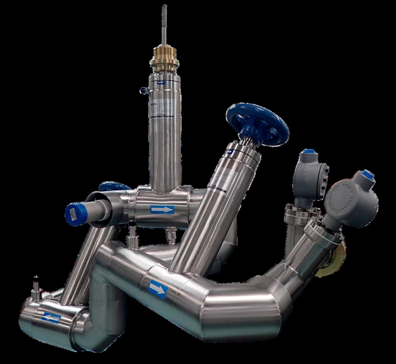
Our application-specific accessory product lineup offers the optimum system solution for any application. Including Liquid Nitrogen, Oxygen and Cryo Liquid Piping.
handle the higher hydrogen content. Alternatively, an additional separation process will need to be added to the BOG to remove hydrogen.
If the BOG is used as fuel gas within the facility, the hydrogen will change the heating value and density of the fuel gas. Storage tank pressure relief valves will need to be checked for proper sizing with a high hydrogen content in the tank vapour space.
The effect of hydrogen on the risk of LNG rollover in the LNG tanks is not well known. Additional studies will be required to determine if the small amount of hydrogen remaining in the LNG can increase rollover effects in stratified LNG tanks.
Solutions to keep LNG peak shavers operational
The simplest solution, of course, is to avoid having hydrogen in the feed gas to a peak shaving facility when possible. Gas utilities that are considering adding hydrogen displacement into the distribution systems should carefully assess the location of the injection point to avoid the inlet of the peak shaving facility, as was done at the Howell facility.
Over time, it is possible that hydrogen will become prevalent in many of the pipelines feeding peak shaving facilities. This will require mitigations to keep these important facilities operational.
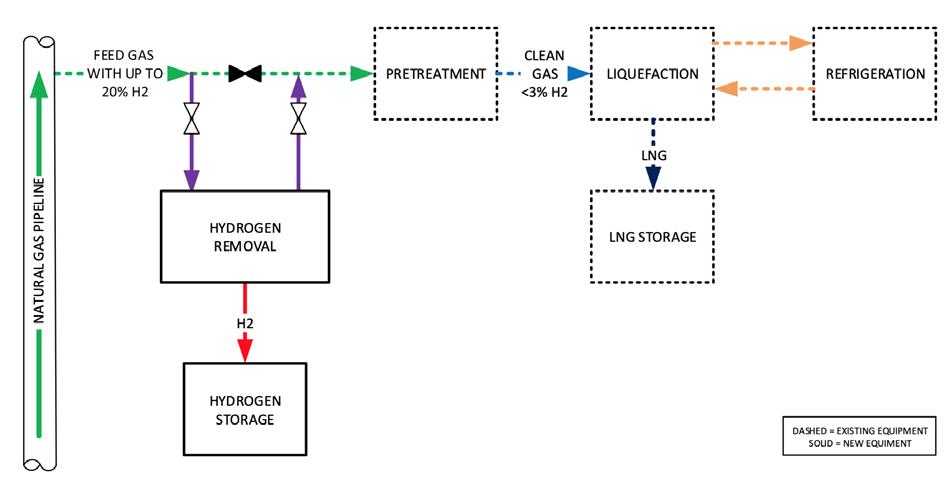
For existing liquefiers, hydrogen removal is recommended prior to the liquefaction process. The simplest arrangement may be to install a separation process prior to the gas pre-treatment system (Figure 3). A solution for an existing LNG facility is membrane separation.
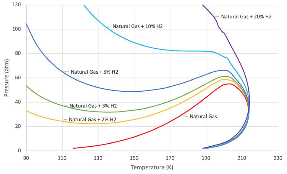
Figure 2. Phase diagram for natural gas with various concentrations of hydrogen.2
Figure 3. Diagram of hydrogen separation from natural gas feed into an LNG peak shaver.
With this process, the mix of hydrogen and natural gas will enter a membrane vessel where the natural gas would pass through while the hydrogen is separated and exits as a low-pressure stream. While 100% separation is not achievable, suitable separation required for LNG liquefaction to continue is likely for a properly designed and installed system.
New facilities may be able to include a separation process within the LNG liquefaction process. This may be a distillation process extracting the hydrogen gas from the liquid LNG stream. However, the refrigeration system would need to be designed for this separation within the liquefaction process. This would preclude such modifications to existing LNG peak shaver facilities.
Handling extracted hydrogen
After the hydrogen has been extracted from the natural gas, there are many ways to handle the hydrogen gas. The easiest method is to vent or flare the gas. For the membrane separation option, the separated hydrogen is at a low pressure and can be easily sent to a low-pressure flare. Hydrogen is not considered a GHG and therefore does not have the same effects on the environment as carbon dioxide or methane.
Alternatively, the hydrogen could be compressed and returned to the pipeline, provided there is enough flow-by in the pipeline so that the hydrogen does not recirculate back into the feed stream of the facility.
Depending upon the quantity of hydrogen separated, the hydrogen by-product may be a useful commodity. Hydrogen may be compressed for storage or liquefied and then sold as a revenue stream. It may also be beneficial to capture the hydrogen for resale or consume it on site as fuel gas. Other options for the hydrogen are to produce green electrical power or fuel for hydrogen vehicles. Depending on the hydrogen’s intended purpose, additional equipment may be necessary to purify the hydrogen extracted by the separation process.
Additional considerations and consultation
Although this article summarises the challenges and potential solutions to mitigate the presence of hydrogen in feed gas for peak shaving facilities, specific conditions must be evaluated before recommendations can be developed for implementation.
Companies, including CB&I, offer consultations based on the design parameters of the facility and can make recommendations that take into consideration the specific concerns of the owner and/or operator.
References
1. ‘Global Methane Initiative – Importance of Methane’,
U.S. Environmental Protection Agency, (30 June 2021), www.epa.gov/gmi/importance-methane. 2. Curve data by AspenTech HYSYS Process simulation software for values from Table 1 using GERG 2008
Equation of State. 3. KIRK, B. S., and ZIEGLER, W. T., ‘A Phase-Equilibrium
Apparatus for Gas-Liquid Systems and the Gas Phase of
Gas-Solid Systems: Application to Methane-Hydrogen from 66.88˚K to 116.53˚K and up to 125 Atmosphere’,
International Advances in Cryogenic Engineering, Vol. 10,
Part 2, Timmerhaus, (1965).
