19 minute read
The power of integration


Geir Moholt, Høglund Marine Solutions, addresses the importance of system integration as the adoption of new fuels, such as LNG, increases complexity on board ships.
ooking back on 2022, one of the overriding themes when it comes to the future of the global shipping fleet will be ‘keeping options open.’ With a lack of certainty when it comes to the eventual fuel mix of the future, but plenty of pressure to switch away from fossil fuels, the shipping industry is a college student waiting until the last minute to pick their major. And rightly so – after all, it is still far too early to predict how a radically different fuel supply chain will evolve over the lifetime of a vessel. The answer to this dilemma, overwhelmingly, is the option to handle LNG, which keeps the door open for bio- or synthetic LNG, ammonia, or even hydrogen, with some modification. Earlier in 2022, Clarkson Research Services reported that 63% of orders in gt terms have been for alternative fuel-capable units. LNG remains the leading choice of fuel, and many owners are also opting for dual-fuel options.
Managing these fuels effectively will be a challenge in itself. These fuels will require dedicated automated fuel management and supply systems that are far more complex than the current standard shipping is used to, which is based around managing heavy fuel oil (HFO). How shipowners, yards, and equipment
suppliers specify and then subsequently use these systems will have a major impact on the overall reliability and performance of future vessels, both newbuilds and those retrofitted to use future fuels. The same goes for LNG carriers and bunkering vessels.
Retrofits of dual-fuel systems can partially de-risk the choices of today and future-proof the investment decisions made amid ongoing fuel uncertainty. By considering how energy can be transferred, stored, and used on board a vessel today and in the future, as well as identifying the similarities and compatibilities across different energy carriers, shipowners can equip their vessels with a multiple use dual-fuel system and eliminate the need for immediately choosing between LNG, ammonia, and methanol from a fuel handling perspective.
A vessel equipped with a dual-fuel system where one fuel system is designed for handling a low vapour pressure combustible liquid at ambient pressures and temperatures, and the other to handle a cryogenic, pressurised combustible and toxic energy carrier – both feeding into an internal combustion engine – will most likely cover any option the future might bring.
With a standard dual-fuel system that can manage HFO/diesel and LNG, the diesel fuel handling side can also be eventually converted to handle synthetic or biofuels, with relative minor impact as long as this is considered from the start. Meanwhile, the other part of the dual fuel system – the one typically handling the LNG – can be made to handle ammonia and hydrogen in the future.
Choosing an integrated automation system (IAS) is more important today than it has been in the past because the number of subsystems with their own control system is increasing and creating huge operational challenges for shipowners. Additionally, system upgrades are becoming especially challenging.
Choosing the right level of integrated automation
Many onboard systems – such as fuel gas supply systems (FGSS) – are delivered as turn-key solutions that come with their own proprietary control system, which can either become integrated into a vessel’s IAS or run in parallel to it, where only the interface between the two has to be specifically tested on installation. This is a low-risk option for shipyards as it avoids many potential problems during commissioning.
However, using a default control system may not be the best option. Yards and owners can choose a dedicated IAS supplier that provides input/output modules, processing power, and user interfaces. All control functions are delivered within this system, making it easier to fix problems and implement modifications. This can require more effort on the shipyard’s part, as it needs to define the scope of the system – but, ultimately, it can be worth the effort in the long run.
With an updated integrated automation and control system, detailed information from different subsystems is available on a single screen; data logging and storage is simplified, and the crew can access the data banks that detail the day-to-day operations of the ship’s critical systems. Consequently, they can analyse and identify the root cause of faults and make decisions that will improve reliability. One person can debug a problem all the way down to input/output level, rather than finding that a bug exists within a proprietary control system which they cannot access, and needing to await support form the company that supplied it.
In addition, it means that just one company is responsible for the IAS, and there is a single point of contact for all automation concerns in the event that further support is needed – there is no need to work with multiple suppliers to fix a problem that might exist in any of their products. Hardware, spare parts, and user interfaces are also consistent, which makes replacements and upgrades easier, and training is simplified.
Unexplained events
Modern IAS on board LNG vessels consist of thousands of input and output signals with widespread signal interfaces and functions. The system solves many tasks, which alone can be trivial, but, put together, become complex.
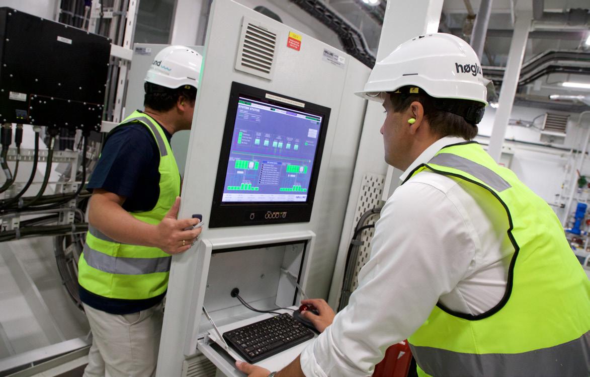
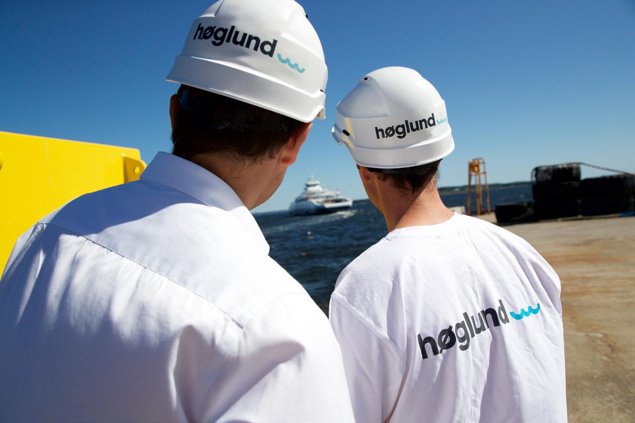
Figure 1. Høglund engineers at work. When a ship is sailing, troubleshooting and repair capabilities depend on the training and tools available to the crew. Systems reliant on programmable logic controllers can experience unexplained events from within various sub-systems, and it can be difficult for crews to recreate problems and fix them. With outdated automation systems, expensive engineer callouts are often required to mend periodic system faults. The engineers will ‘patch’ the system, but will often not find the root cause of the problem because the data outputs from system logs are outdated, unreliable, and inaccessible. Even more modern subsystems may appear to be working, but there is no guarantee they are operating properly or optimally. Crews may accept this if they cannot find the problem but can find a workaround. Having invisible unreliability within an automation system can be a significant financial burden for shipowners, often without them even knowing about it. With time, the cost


of maintaining an old system will outweigh the expense of an entirely new automation system on board.
Update with care
Shipowners looking to update their automation system should consider their approach carefully or risk spending more money on a method that initially seems cost-effective but ultimately comes with considerable overheads. One suggested measure is to start with an upgrade of the ‘top-system’, which includes operator stations and graphics. Then, at the next yard stay, providers upgrade the ‘bottom-system’, including major hardware components such as computer processing units and input/output cabinets.
While this approach may seem reasonable as the cost is spread over a number of years, owners can effectively pay twice for automation refits and get locked into contracts with hardware suppliers with no flexibility on upgrade options. The complete refit of an overarching integrated automation and control system will amount to approximately 60 – 80% of the cost of the step-by-step approach.
By combining the automation systems into an overarching integrated automation and control system, owners also get the financial benefits of automation in much the same way they would by buying a modern newbuild. Complexity is reduced, reliability is increased, and day-to-day maintenance is made significantly easier. Owners and crew are then also able to leverage other cost-saving benefits through improved energy management performance.
Efficiency gained from integrated automation provides a gateway to big data utilisation. Many onboard systems need to interact with each other and generate huge amounts of data while doing so. This information can either be a burden for crew or shoreside teams to manage or a source of valuable operational insights. If handled correctly, it can be used to optimise operations, diagnose faults, and ensure more reliable operations.
Teamwork is critical
engineers, automation experts, and system integrators understand the benefits of working together to meet the high safety and reliability standards that shipping demands. There are considerable engineering challenges to effectively integrating automation and gas handling systems on gas newbuilds, for example. Without properly considering automation and integration, the vessel is at risk of becoming difficult to operate and maintain.
Overcoming technical challenges
LNG bunkering vessel design has presented a series of technical challenges that have required specialist expertise. Høglund Marine Solutions delivered the IAS to the MV Cardissa, an LNG bunkering vessel operating for Shell Western LNG.1 Back in 2017, this was a new type of small scale LNG vessel, and it was necessary to change many details from initial specifications as Høglund worked with its clients to develop the best solutions for this emerging segment.
While most of the components installed on board were standard, the way they were to be used differentiated from typical operation principles. Høglund used its software knowledge to customise the system to give the operators an overview of the plant while also ensuring control loops were working as intended. In this instance, Høglund’s playback functions were particularly important, which allowed crew and operators to analyse events on the level of individual inputs and outputs. On such a complex vessel, this was essential.
Another challenge was how to measure and report fuel consumption from boilers, engines, and gas combustion units when calculating delivered LNG fuel for bunkering LNG-powered vessels. Since the custody transfer system was a standard delivery, it was not that easy to add another calculation to the system, but the equation was known, and the IAS had the data – therefore, the function was implemented there.
Due to the specific regulatory requirements for LNG as a fuel, it is more important than ever that designers, yards,
Better performance
A large part of the world’s fleet sails with non-optimal systems when it comes to automation and control. Driven by environmental regulation, the number of systems on board modern vessels is rapidly increasing and becoming more diverse and complex. By giving more care and attention to the fields of integration and automation, owners and operators will be able to more effectively drive fuel savings, improve environmental performance, and provide owners and operators with a more accurate overview of a ship’s performance and operational data in compliance with regulations.
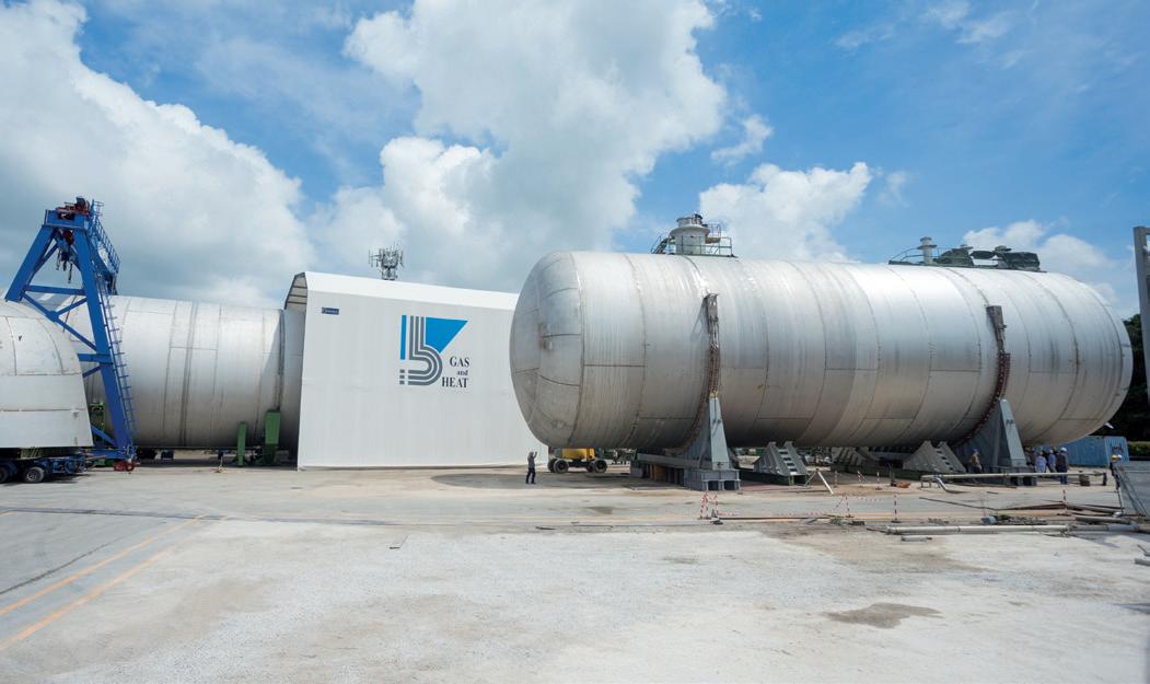
Figure 2. Høglund designs, develops, and delivers integrated marine solutions for all types of vessels worldwide.
References
1. ‘Høglund forges new partnerships in
LNG and chemical tanker automation’,
Ship&Offshore, (2017), www.shipandoffshore. net/news/shipbuilding/detail/news/ hoeglund-forges-new-partnerships-in-lngand-chemical-tanker-automation.html


Cryogenic Valves


UNI EN ISO 9001:2015UNI EN ISO 9001:2015 PRODUCT CERTIFICATIONS BS OHSAS 18001:2007 BS OHSAS 18001:2007 Health & Safety ManagementHealth & Safety ManagementHealth & Safety Management

UNI EN ISO 14001:2015 UNI EN ISO 14001:2015 Environmental ManagementEnvironmental ManagementEnvironmental Management COMPANY CERTIFICATIONS

COMPANY UNI EN ISO 9001:2015 CERTIFICATIONS
PRODUCT UNI EN ISO 9001:2015 PRODUCT CERTIFICATIONS CERTIFICATIONS
Fire Safe ISO 10497–API 607–API 6FA
PRODUCT EAC-CU-TR 010/2011 CERTIFICATIONS For EAC Countries
Fire Safe ISO 10497–API 607–API 6FA
Fire Safe EAC-CU-TR 010/2011 ISO 10497–API 607–API 6FA For EAC Countries
EAC-CU-TR 010/2011 PED 2014/68/EU For EAC Countries
Fugitive Emission EN ISO 15848-1 EN ISO 15848-2 BS OHSAS 18001:2007 BS OHSAS 18001:2007 Health & Safety ManagementHealth & Safety Management Fugitive Emission
EN ISO 15848-1 UNI EN ISO 14001:2015 EN ISO 15848-2 UNI EN ISO 14001:2015 Environmental ManagementEnvironmental Management
Fugitive Emission EAC-CU-TR 012/2011 EN ISO 15848-1 For EAC Countries EN ISO 15848-2 EAC-CU-TR 032/2013 For EAC Countries
ATEX 2014/34/EU EAC-CU-TR 012/2011 EAC-CU-TR 012/2011 For EAC Countries For EAC CountriesCRN for Canada EAC-CU-TR 032/2013 EAC-CU-TR 032/2013 For EAC Countries For EAC Countries PRODUCT CONSTRUCTION CERTIFICATIONS NORMS & REGULATIONS
Fire Safe ISO 10497–API 607–API 6FA Fugitive Emission EN ISO 15848-1 EN ISO 15848-2 EAC-CU-TR 010/2011 PED 2014/68/EU For EAC Countries ATEX 2014/34/EU EAC-CU-TR 012/2011 For EAC Countries CRN for Canada EAC-CU-TR 032/2013 For EAC Countries CONSTRUCTION NORMS & REGULATIONS
Fire Safe ASME/ANSI B16.34 ISO 10497–API 607–API 6FA ASME/ANSI B1.20.1 Fugitive Emission ASME/ANSI B16.5 EN ISO 15848-1 EN ISO 15848-2 ASME VIII ASME B16.10
EAC-CU-TR 010/2011CONSTRUCTION PED 2014/68/EU For EAC CountriesNORMS & REGULATIONS ATEX 2014/34/EU EAC-CU-TR 012/2011 For EAC Countries CRN for Canada EAC-CU-TR 032/2013 For EAC Countries
ASME/ANSI B16.34 MATERIALS SS 316/316L, Duplex F51, SuperDuplex ASME/ANSI B1.20.1 F53/F55, ASME/ANSI B16.5 A105, LF2, Monel, ASME VIII Alloy 625/Incoloy 825, C-276, Titanium, ASME B16.10 6MO, Others on demand
PED 2014/68/EU API 598 ATEX 2014/34/EU API 6D API 602 CRN for Canada NACE MR 01-75 / MR 01-03 Norsok
CONSTRUCTION NORMS & REGULATIONS ASME/ANSI B16.34 MATERIALS SS 316/316L, Duplex F51, SuperDuplex ASME/ANSI B1.20.1 F53/F55, ASME/ANSI B16.5 A105, LF2, Monel, ASME VIII Alloy 625/Incoloy 825, C-276, Titanium, ASME B16.10 6MO, Others on demand
PED 2014/68/EUCONSTRUCTION API 598 NORMS & ATEX 2014/34/EUREGULATIONS API 6D API 602 CRN for Canada NACE MR 01-75 / MR 01-03 Norsok
ASME/ANSI B16.34 MATERIALS SS 316/316L, Duplex F51, SuperDuplex ASME/ANSI B1.20.1 F53/F55, ASME/ANSI B16.5 A105, LF2, Monel, ASME VIII Alloy 625/Incoloy 825, C-276, Titanium, ASME B16.10 6MO, Others on demand
API 598 API 6D API 602 NACE MR 01-75 / MR 01-03 Norsok
BALL & DBB SPLIT BODY FLOATING, TRUNNION & ACTUATED VALVESBALL & DBB SPLIT BODY FLOATING, TRUNNION & ACTUATED VALVESINTEGRAL ONE PIECE FLOATING BALL & DBB VALVES INTEGRAL ONE PIECE FLOATING BALL & DBB VALVESINTEGRAL ONE PIECE FLOATING BALL & DBB VALVES INTEGRAL ONE PIECE FLOATING BALL & DBB VALVESINTEGRAL ONE PIECE FLOATING BALL & DBB VALVESINSTRUMENTATION VALVES & MANIFOLDS INSTRUMENTATION VALVES & MANIFOLDSINSTRUMENTATION VALVES & MANIFOLDS INSTRUMENTATION VALVES & MANIFOLDSINSTRUMENTATION VALVES & MANIFOLDS

• ASME Class – 150lb to 2500lbASME Class – 150lb to 2500lb 10000 • API 3000 / 5000 / 10000 Size – 1/2” to 8” (FB & RB) • Size – 1/2” to 8” (FB & RB) •Soft Seated & Metal Seated Soft Seated & Metal Seated •Lever, Gearbox or Actuated Lever, Gearbox or Actuated • Temperature Range -46°C to +240°CTemperature Range -46°C to +240°C • High Temperature on demandHigh Temperature on demand • Low Temperature on demand Low Temperature on demand
CONNECTIONS CONNECTIONSCONNECTIONS
From 1/2” to 8” From 1/2” to 8”From 1/2” to 8”
Threaded ThreadedThreaded
Flanged FlangedFlanged Welded (BW or SW) Hub Welded (BW or SW) Hub Welded (BW or SW) Hub Application LNG
RATING RATING RATING
ASME Class – 150lb to 2500lbASME Class – 150lb to 2500lbASME Class – 150lb to 2500lb
API 3000 / 5000 / 10000 / API 3000 / 5000 / 10000 / 15000API 3000 / 5000 / 10000 / 1500015000
DESIGN DESIGNDESIGN
Single or Double Block with Single or Double Block with Single or Double Block with optional Bleed (SB-SBB-DB-DBB)optional Bleed (SB-SBB-DB-DBB)optional Bleed (SB-SBB-DB-DBB) Integral Ball Design: Soft & Metal SeatIntegral Ball Design: Soft & Metal SeatIntegral Ball Design: Soft & Metal Seat Magenta MILANO BONNET Screwed, O.S.&Y. Bolted, BONNET Screwed, O.S.&Y. Bolted, BONNET Screwed, O.S.&Y. Bolted, Antitamper, Extended Locking device, Antitamper, Extended Locking device, Antitamper, Extended Locking device, Cryogenic service Cryogenic serviceCryogenic service


SAMPLING & INJECTION DBB VALVES SAMPLING & INJECTION DBB VALVESSAMPLING & INJECTION DBB VALVES


HeadquartersThese DBBs are used for sampling & Injection These DBBs are used for sampling & Injection These DBBs are used for sampling & Injection purpose and for further analysis of the process.purpose and for further analysis of the process.purpose and for further analysis of the process.
Valves are designed with Integral Body and Valves are designed with Integral Body and Valves are designed with Integral Body and
Integral Sampling Probe (Not Welded). Integral Sampling Probe (Not Welded). Integral Sampling Probe (Not Welded). 4000 sqmProbe length is defined in acc. to the application requirements and the pipeline diameter - upon indication. Indra can supply Wake Frequency Probe length is defined in acc. to the application requirements and the pipeline diameter - upon indication. Indra can supply Wake Frequency Probe length is defined in acc. to the application requirements and the pipeline diameter - upon indication. Indra can supply Wake Frequency of which 3000 sqm and Bending Stress Calculations to ensure the correct selection of the Probe Length and and Bending Stress Calculations to ensure the correct selection of the Probe Length and and Bending Stress Calculations to ensure the correct selection of the Probe Length and the valve optimum performance in time.the valve optimum performance in time.the valve optimum performance in time. of production area
CONNECTIONS CONNECTIONS
From 1/2” to 8” From 1/2” to 8” Threaded Threaded Flanged Flanged Standard and special materials Welded (BW or SW) Hub Welded (BW or SW) Hub
CONNECTIONS CONNECTIONSCONNECTIONS
From 1/8 ” to 2” From 1/8 ” to 2”From 1/8 ” to 2” NPT, BSPP, BSPT, BW, SW NPT, BSPP, BSPT, BW, SWNPT, BSPP, BSPT, BW, SW
RATING RATING RATING
6.000 - 10.000 PSI (threaded types)6.000 - 10.000 PSI (threaded types)6.000 - 10.000 PSI (threaded types) SCH. 40, 80, 160, XXS (BW-SW version)SCH. 40, 80, 160, XXS (BW-SW version)SCH. 40, 80, 160, XXS (BW-SW version)
SS 316/316L Nace XM-19 Inconel 718
RATING RATING
ASME Class – 150lb to 2500lb API 3000 / 5000 / 10000 / 15000 ASME Class – 150lb to 2500lb API 3000 / 5000 / 10000 / 15000 Monel DESIGN Single or Double Block with DESIGN Single or Double Block with Others optional Bleed (SB-SBB-DB-DBB)optional Bleed (SB-SBB-DB-DBB) Integral Ball Design: Soft & Metal SeatIntegral Ball Design: Soft & Metal Seat on demand
BONNET BONNET
Screwed, O.S.&Y. Bolted, Screwed, O.S.&Y. Bolted, Antitamper, Extended Locking device, Antitamper, Extended Locking device, Cryogenic service Cryogenic service
BONNET BONNET BONNET
Screwed, O.S.&Y. Bolted, Antitamper, Screwed, O.S.&Y. Bolted, Antitamper, Screwed, O.S.&Y. Bolted, Antitamper, Extended Locking device, Cryogenic serviceExtended Locking device, Cryogenic serviceExtended Locking device, Cryogenic service
MONOFLANGE VALVES – SLIM LINE SB - SBB - DB - DBB MONOFLANGE VALVES – SLIM LINE SB - SBB - DB - DBBMONOFLANGE VALVES – SLIM LINE SB - SBB - DB - DBB CONNECTIONS CONNECTIONSCONNECTIONS
Inlet: 1/2” to 4” flanged Inlet: 1/2” to 4” flanged Inlet: 1/2” to 4” flanged Outlet: Threaded & FlangedOutlet: Threaded & FlangedOutlet: Threaded & Flanged
RATING RATING RATING
ASME Class – 150lb to 2500lbASME Class – 150lb to 2500lbASME Class – 150lb to 2500lb API 3000 / 5000 / 10000 API 3000 / 5000 / 10000API 3000 / 5000 / 10000
SAMPLING & INJECTION DBB VALVESSAMPLING & INJECTION DBB VALVES
Test These DBBs are used for sampling & Injection purpose and for further analysis of the process. Valves are designed with Integral Body and These DBBs are used for sampling & Injection purpose and for further analysis of the process. Valves are designed with Integral Body and Integral Sampling Probe (Not Welded). Integral Sampling Probe (Not Welded). All tests are carried Probe length is defined in acc. to the application requirements and the pipeline diameter - upon Probe length is defined in acc. to the application requirements and the pipeline diameter - upon out in houseindication. Indra can supply Wake Frequency and Bending Stress Calculations to ensure indication. Indra can supply Wake Frequency and Bending Stress Calculations to ensure the correct selection of the Probe Length and the correct selection of the Probe Length and the valve optimum performance in time.the valve optimum performance in time.
BONNET BONNET BONNET
Screwed, O.S.&Y. Bolted, Antitamper, Screwed, O.S.&Y. Bolted, Antitamper, Screwed, O.S.&Y. Bolted, Antitamper, Extended Optional locking device,Extended Optional locking device,Extended Optional locking device, Cryogenic service Cryogenic serviceCryogenic service
CUSTOMIZED CONFIGURATIONCUSTOMIZED CONFIGURATIONCUSTOMIZED CONFIGURATION
CONNECTIONS
From 1/8 ” to 2” NPT, BSPP, BSPT, BW, SW
RATING RATING
6.000 - 10.000 PSI (threaded types)6.000 - 10.000 PSI (threaded types) SCH. 40, 80, 160, XXS (BW-SW version)SCH. 40, 80, 160, XXS (BW-SW version)
BONNET BONNET
Screwed, O.S.&Y. Bolted, Antitamper, Screwed, O.S.&Y. Bolted, Antitamper, Extended Locking device, Cryogenic serviceExtended Locking device, Cryogenic service
MONOFLANGE VALVES – SLIM LINE SB - SBB - DB - DBBMONOFLANGE VALVES – SLIM LINE SB - SBB - DB - DBB
CONNECTIONS
Inlet: 1/2” to 4” flanged Outlet: Threaded & Flanged
RATING RATING
ASME Class – 150lb to 2500lbASME Class – 150lb to 2500lb API 3000 / 5000 / 10000 API 3000
BONNET BONNET
Screwed, O.S.&Y. Bolted, Antitamper, Screwed, O.S.&Y. Bolted, Antitamper, Extended Optional locking device,Extended Optional locking device, Cryogenic service Cryogenic service
CUSTOMIZED CONFIGURATIONCUSTOMIZED CONFIGURATION
EngineeringEngineering ManufacturingManufacturing 3D CheckingManufacturing 3D Checking3D Checking NDT Testing3D Checking 3D Checking NDT TestingBunker “High Pressure Test” 3D Checking NDT TestingBunker “High Pressure Test” NDT Testing 100% Pressure TestingBunker “High Pressure Test” NDT Testing 100% Pressure TestingBunker “High Pressure Test” 100% Pressure TestingNDT Testing Cryogenic test 100% Pressure Testing