MEFI Fuel Injection
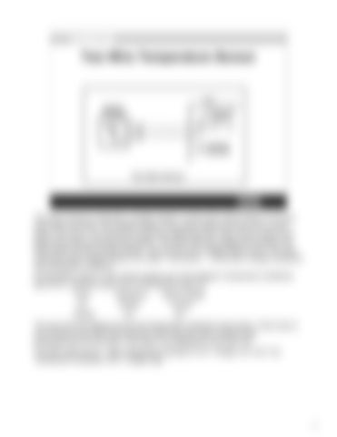
Two Wire Temperature Sensor
This type of sensor is basically a variable resistor in series with a fixed resistor of a known value within the ECM. The variable resistor in the sensor determines how much current flows in the circuit. The amount of current flow determines how much of the 5 volts on the signal wire drops across the fixed resistor. The ECM reads the voltage level between the fixed resister and the variable resistor. This is known as a voltage divider circuit. The most commonly used variable resistors are called “Thermistors”. A thermistor changes resistance with temperature variations. All thermistors used on Volvo Penta engines are of the Negative Temperature Coefficient type (NTC), resistance goes down as temperature goes up. Temp
Resistance
Signal Voltage
UP
DOWN
DOWN
DOWN
UP
UP
The scan tool only displays the current temperature indicated by the sensor. If that value is out of limits for the ECM, the ECM sets a fault code and uses a default value preprogrammed into the ECM. That value is not displayed on the scan tool. The fault codes set are “High Temperature Indicated or ECT Voltage Low” and “Low Temperature Indicated or ECT Voltage High”.
77


