2 minute read
Ignition Control Module


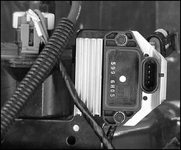
The external ignition control (IC) module is mounted on a bracket with the coil on the back of the engine. This is a one piece assembly.
The IC module contains the coil driver. It receives an ignition timing signal from the ECM and triggers the coil.
Pin A…..Ignition Voltage
Pin B…..Ignition Timing Signal
Pin C…..Ground
Pin D…..Coil Driver
NOTE!If the crankshaft was moved while distributor was out, complete ignition timing procedure must be followed. See below.
Gi and GXi models GL models: See Electric, Fuel and Ignition Workshop Manual 7743454.
1. Rotate the crankshaft balancer clockwise until the alignment marks on the crankshaft balancer (1) are aligned with the tabs on the engine front cover (2) and the number 1 piston is at top dead center of the compression stroke.
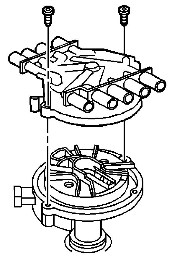
2. If not already removed, remove and discard the distributor cap screws.
3. Remove the distributor cap
4. Install NEW distributor gasket onto the distributor.
9. Once the distributor is fully seated, align the distributor rotor segment with the number 8 pointer (1) that is cast into the distributor
Note!If the distributor rotor segment does not come within a few degrees of the number 8 pointer, the gear mesh between the distributor and camshaft may be off a tooth or more. Repeat the procedure again in order to achieve proper alignment.
Alternator with mounting bracket.
10. Install the distributor clamp bolt. and Tighten the bolt to 25 N.m (18 lb. ft.).
Connect:
11. Install the distributor cap and NEW distributor cap bolts.Tighten the screws to 2.4 N.m (21 lb. in).
12. Set timing, GL Models see Electrical Fuel and Ignition Workshop Manual 7743454. Gi and GXi Models see EFI Diagnostic Workshop Manual 7742218 On Board Repair.
13. Install distributor cap and high tension leads. See the General Information section in Electrical/Ignition/Fuel Service Manual for correct firing order and spark plug wire routing.
14. Install oil pressure sending unit.
15. All electrical connections. Apply black neoprene dip, or equivalent, on all exposed connections.
16. Fuel lines to carburetor and fuel pump or throttle body and fuel pump/vapor separator.
17. Throttle cable.
18. All water hoses, and close all drain petcocks.
19. Both crankcase ventilation hoses.
20. Battery cables.
9.Once the distributor is fully seated, align the distributor rotor segment with the number 6 pointer (1) that is cast into the distributor base. If the distributor rotor segment does not come with a few degrees of the number 6 pointer (1), the gear mesh between the distributor and camshaft may be off a tooth or more. Repeat the procedure again in order to achieve proper alignment.
Notice: Refer to Fastener Notice in Cautions and Notices.
10.Install the distributor clamp bolt.
Tighten
Tighten the distributor clamp bolt to 25 N.m (18 lb ft).
11.Install the distributor cap and NEW distributor cap bolts.
Tighten
Tighten the distributor cap bolts to 2.4 N.m (21 lb in).


