1 minute read
Knock Sensor Diagnostics


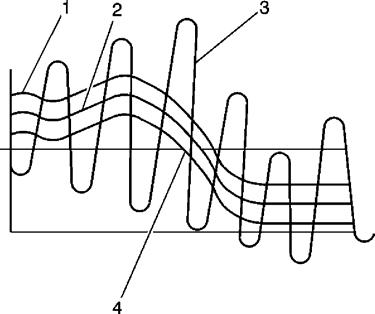
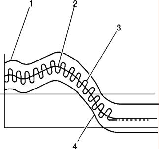
The ECM checks the knock sensor and related wiring by comparing the actual knock signal to the assigned voltage range. A knock sensor signal (#3 in theabove diagrams) should vary outside the assigned voltage range (#1 is the upper limit and #4 is the lower limit) as shown in the normal KS (knock sensor) figure. If the ECM detectsa KS signal within the assigned voltage range as shown in the abnormal KS figure, then a code 44 is set for the affected knock sensor.
Technician diagnostics for the sensor and circuit include checking continuity through the sensor and circuit, and hooking up an AC voltmeter or an oscilloscope to the sensor and gently tapping on the sensor with a metal object. Tapping on thesensor should produce an AC voltage on the voltmeter.