3 minute read
EVC-ecInput / Output Examples


Throttle lever voltage from the potentiometer is a direct input (hard wired) to the HIU. The HIU sends throttle lever voltage input over the CAN bus as an indirect output to the ECU.
The ECU receives throttle lever voltage as an indirect input over the CAN BUS. The ECU translates the throttle lever voltage input into shift lever position and gear request and sends the shift request back to the PCU as an indirect output. The shift actuator is hardwired to the PCU, so it is a direct output of the PCU. The ECU uses the throttle status indirect input to anticipate load and increase/decrease fuel to the engine as requested.
Speed Density System
RPM X MAP (X)ECT (X) IAT (X) TPS (X) B+ = Pulse Width
MAX RPM BARO Load + Modifiers = Pulse Width
Speed Density fuel injection is a term used to describe the calculated process by which the ECM determines the correct amount of fuel to inject for the operating conditions. The most important input is engine speed and the second most important isdensity of the air in the intake, thus Speed Density.
“MAX RPM”and “BARO”in the equation above are for reference points. Without these reference points, “MAP”and “RPM”would be meaningless.
“MAX RPM”is where the rpm limiter is set and “BARO”is the barometric pressure for that “key on”weather and altitude and sets the starting point for fuel delivery.
ECT: Cold engine gets more fuel and more timing; hot engine gets less fuel and less timing.
IAT: Cold air gets more fuel and timing; hot air gets less fuel andless timing
TPS: TPS only has an effect on fuel when it is moving. Rapid opening:add more fuel, rapid closing: subtract fuel. When TPS is constant it has no effect on fuel delivery. This is the EFI replacement for the carbureted accelerator pump.
B+: Fuel injectors are rated to flow a given volume of fluid at a given supply voltage at a particular pulsewidth at a given pressure.
KS: When engine knock is present, the ECM can add fuel and or retard timing to eliminate knock.
Volvo Penta marine electronic fuel injection systems are “Speed Density”systems whether they are TBI or MPI systems.
The ECM uses the RPM signal (CKP from MEFI 4 engines and “Ref High”from MEFI 1 and 3 engines) to compute speed and the MAP signal to measure air density in the intake manifold.
The Manifold Absolute Pressure (MAP) sensor input determines howmuch fuel the running engine receives. MAP is the sensor that has the greatest authority in controlling pulsewidth (after the engine is running).
After the PCM determines the base pulsewidth based on the CKP and MAP inputs, it will be further modified based on throttle position, coolant temperature, and intake air temperature.
Volvo Penta scan tools read in inches of mercury (in hg) or PSI not inches of vacuum. To convert from “in hg”to “in vac”, take the number 30 and subtract the number in “in hg”and the result is “in vac”.
Example: 12 in hg in the chart above. 30 -12 = 18 (in vac)
To convert inches of mercury to PSI, divide by 2.
Example: 14 in hg in the chart above. 14 divided by 2 = 7 (PSI).
Spark Advance (Degrees BTDC)
The ECM calculates total degrees of spark advance based upon theengine RPM and MAP sensor inputs. This combination of base timing and calculated advance forms the IC signal and controls spark timing.
Fuel injected engines need fuel and spark at the right times. Carbureted engines have the same fuel and spark requirements. The table above shows the electronic replacements for the old mechanical and vacuum advance systems used on older carbureted engines.
The table above is an actual spark table from one of Volvo Penta’s fuel injected engines. As RPM increases with no change in MAP, timing advances (mechanical advance). As pressure decreases (vacuum increases) with no change in RPM, timing increases (Vacuum advance).
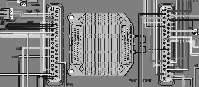
The MEFI 4 ECM has 3 power grounds. They are located in the J1 connector at pins 13, 28, and 29. Prior to the 2003 model year, all 3 ground back at the engine flywheel housing on the grounding studs. Starting with the 2003 model year the 3 grounds are isolated from the other grounds. That means that the eyelet (with 3 wires) is located remotely and away from the 2 ground studs on the back of the engine. If all 3 grounds are open the engine will not start or run and the scan tool will be unable to communicate with the ECM. A ground point that is loose or corroded can cause a poor running engine that is hard to diagnose.
The MEFI 4 ECM has 1 continuous battery feed circuit located in connector J2 at pin 1. This circuit is used by the ECM to internally provide all other circuits out of the ECM with power. The ECM also uses this as the B+ input for fuel injector pulsewidth. It can be seen on the scan tool as “Battery Voltage”.
The MEFI 4 ECM has 1 ignition feed circuit located in connector J2 at pin 19. This feed circuit comes from the ignition relay and should have B+ on it anytime the key is on. This circuit is the “wake up”signal to the ECM.
All of these circuits have to be functioning properly for the ECM to function properly. A loss of any of these circuits can cause anything from a poor running engine to a “will crank but not start”condition. Loss of either the B+ or the ignition feed will alsocause a “no communication with the scan tool”condition in addition to the “no start”condition.


