1 minute read
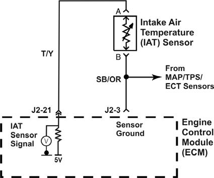
IAT Circuit


IAFM Engines
The ECM sends out 5 volts to the sensor on the signal wire. As the temperature of the sensor changes, it’s resistance changes. As the sensor’s resistance decreases, the current flow in the circuit increases. As the current increases, the voltage drop across the fixed resistor in the ECM increases. This causes the voltage availableat the A/D converter (between the fixed resistor and the sensor) to be lower as the sensor’s temperature rises. An open circuit in either the signal wire or the sensor return will set a “voltage high”fault. A “voltage high”fault is also a “low temperature indicated”fault.
The EFI manual has temperature/resistance charts for both the ECT and the IAT sensors. These charts are located at the DTC test for the fault.
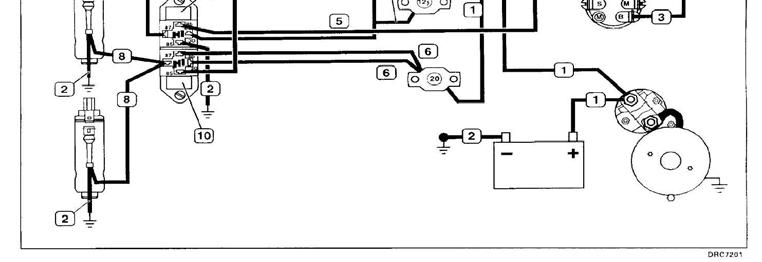
B+ is a fuel delivery modifier. As battery voltage goes down, injector pulsewidth must go up for the volume of fuel delivery from the injector to remain constant. As the voltage goes up, the injector will open more easily and quickly, so injector pulsewidth must go down to maintain the correct volume of fuel in the cylinder.
MEFI 3, 4 and 4b ECM’s have a limited range of pulsewidth adjustment for B+. Therefore, if the voltage supply to the ECM is low, the engine will run too lean and if the voltage supply to the ECM is too high the engine will run too rich. Either condition will cause a poor running condition.
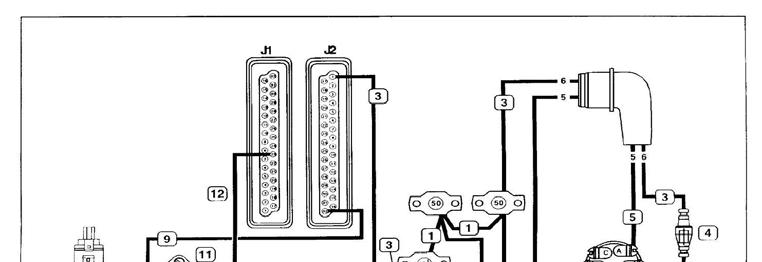
This B+ voltage input can be viewed with a scan tool. It is named “Battery Voltage”. The wiring diagram above is a typical MEFI 1 or 3 wiring diagram. These MEFI wiring diagrams were divided up by system. This picture is the B+ and fuel pump systems. MEFI 4 EFI system wiring diagrams show the entire engine system on one diagram. On MEFI 3 and MEFI 4 systems J2-1 provides B+ information to the ECM and also provides all power for the ECM.