5 minute read
519 Telehandler ELECTRICAL


Electrical System Tests
NOTE: Use the troubleshooting flow charts for the sequence of component testing and the following steps for test locations and procedures. Always refer to the wiring schematics when doing circuit testing for a better understanding of the circuit.
Warning
When the test involves turning over the engine or starting the engine, use test leads long enough to read the multimeter from the operator’s seat or standing clear of the machine.
NOTE: Use a multimeter for all tests. ALWAYS install the ground (-) test lead to a clean, bare metal surface on the engine or frame.
Battery Test
Step 1
Warning
If there is no voltage, the battery has an internal open circuit. Connecting a charger or auxiliary battery to a battery with an open circuit can cause a battery explosion.
If there is voltage, but is less than 12 volts, proceed to the next step.
Step 2
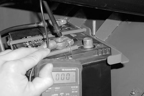
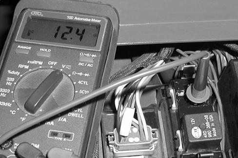
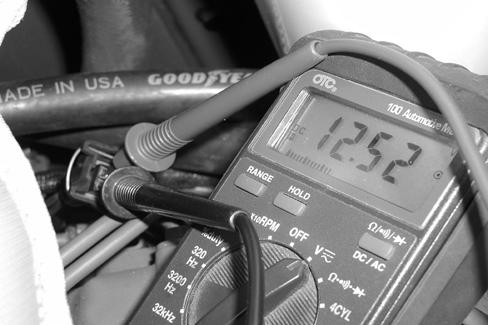
Set the multimeter to DC volts. Connect the multimeter positive (+) test lead to the positive post (1) and the negative (-) test lead to the negative post (2) of the battery. The multimeter should read 12 to 13 volts.
If there is no voltage, replace the battery.
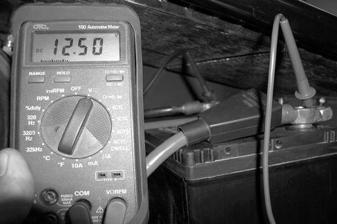
Remove the positive (+) battery cable (1) from the battery. Connect the multimeter negative (-) test lead to the positive battery cabl e (1). Be sure the cable end is not in contact with any metal surfaces. Connect the positive (+) test lead to the positive (+) post (2) of the battery. The multimeter should read 0 volts.
If there is voltage between the positive battery cable (1) and the battery post (2), check the wiring for shorts to ground.
If there is no voltage, recharge or replace the battery. Install the positive (+) battery cable (1) on the battery.
Fuse Power Tests
Step 3
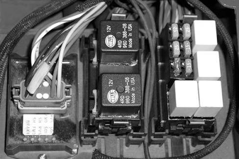
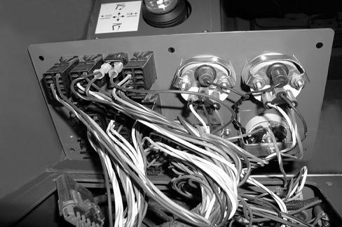
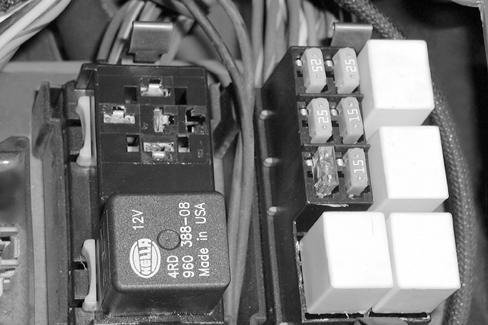
Open the fuse panel cover (1). Connect the positive (+) test lead to the bottom terminal of Fuse 1 to test for battery 12-volt power to the fuse panel. The multimeter should read 12 to 13 volts.
If there is no voltage, replace the 60-amp in-line fuse under the starter relay, or repair or replace the wires between the battery and the fuse panel.
Step 4
G1007040
Connect the positive (+) te st lead to the front (top side) terminal of Fuses 2 through 6. Turn the key switch to the ON position. The multimeter should read 12 to 13 volts.
If there is no voltage, proceed to Step 12.
Ignition Relay Tests
STEP 5
Connect the positive (+) test lead to the right side terminal (#3) of the relay socket. The multimeter should read 12 to 13 volts.
Step 6
If there is no voltage, replace the 60-amp in-line fuse by the engine, or repair or replace the wires between the relay socket and the battery.
If there is 12 to 13 volts, proceed to the next step.
Connect the positive (+) test lead to the bottom terminal (#2) of the relay socket. Turn the key to the ON position. The multimeter should read 12 to 13 volts.
If there is no voltage, proceed to Step 12.
If there is 12 to 13 volts, but the relay does not work, replace the relay.
Starter Tests
STEP 7
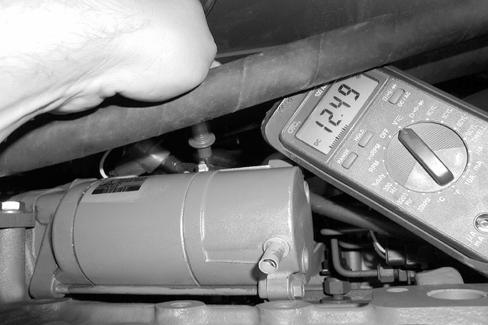
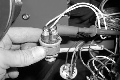
Connect the positive (+) test lead to the battery terminal of the starter. The multimeter should read 12 to 13 volts.
If there is no voltage, clean or replace the positive (+) battery cable between the starter and the battery.
If there is 12 to 13 volts, proceed to the next step.
Step 9
Warning
When the test involves turning over the engine or starting the engine, use test leads long enough to read the multimeter from the operators seat or standing clear of the machine.
Step 8
Connect the positive (+) te st lead to the starter terminal (located just below the battery terminal) of the starter solenoid. Turn the key switch to the ON position and press the starter button. The multimeter should read 12 to 13 volts.
If there is no voltage, proceed to the next step. If there is 12 to 13 volts, and the starter does not turn over the engine, repair or replace the starter and/or the starter solenoid.
Key Switch And Starter Switch Tests
Step 10
Step 11
If there is 12 to 13 volts, proceed to the next step.
Step 13
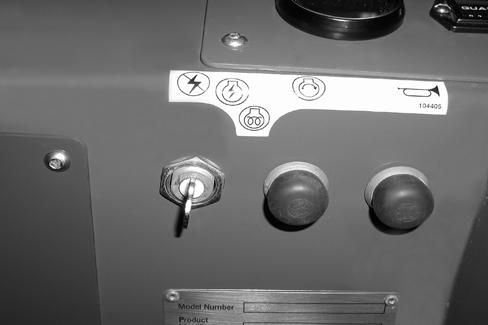
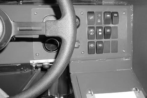
Connect the positive (+) test lead to the ignition (blue/ red wire) terminal of the key switch. Turn the key switch to the ON position. The multimeter should read 12 to 13 volts.
If there is no voltage, replace the key switch. If there is 12 to 13 volts, proceed to Step 18.
Step 14
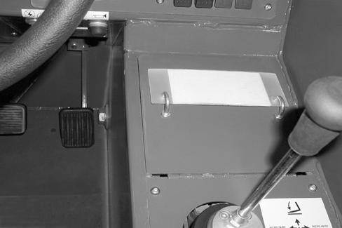
Remove the six screws (1) from the instrument
(2).
Step 12
Connect the positive (+) test lead to the battery (red wire) of the key switch. The multimeter should read 12 to 13 volts.
If there is no voltage, check the ignition fuse (fuse #1) or the wires to the battery.
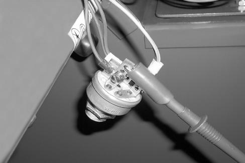
Connect the positive (+) test lead to the white/blue wire terminal of the starter button. Turn the key switch to the ON position. With the transmission lever in neutral the multimeter should read 12 to 13 volts.
If there is no voltage, check the transmission fuse (fuse #2). If the fuse is not open, proceed to the next step.
If there is 12 to 13 volts, proceed to the next step.
Step 15
Step 17
G0208001
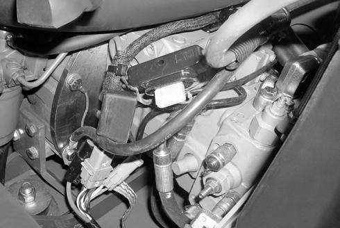
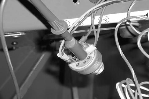
Connect the positive (+) test lead to the black/yellow wire terminal on the transmission control module. Turn the key switch to the ON position. The multimeter should read 12 to 13 volts.
If there is no voltage, replace the wire between the transmission control module and the fuse.
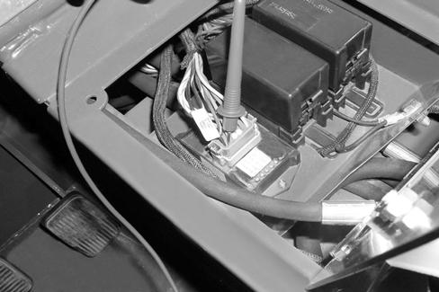
If there is 12 to 13 volts, proceed to the next step.
Step 16
G0208003
Connect the positive (+) test lead to the white/blue wire terminal of the tr ansmission control module. Turn the key switch to the ON position. With the transmission lever in neutral the multimeter should read 12 to 13 volts.
If there is no voltage, replace the transmission lever/ switch assembly.
If there is 12 to 13 volts, proceed to the next step.
Connect the positive (+) test lead to the white wire terminal of the starter button. Place the transmission lever in the neutral position, turn the key switch to the ON position and press the starter switch button. The multimeter should read 12 to 13 volts.
If there is no voltage, replace the starter switch.
If there is 12 to 13 volts, but there was no voltage at the starter solenoid terminal (Step 9), repair or replace the wire between the switch and starter solenoid.

STEP 19
STEP 21
Install the instrument panel using the six screws.
FUEL SHUT-OFF SOLENOID TEST
STEP 20
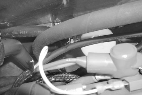
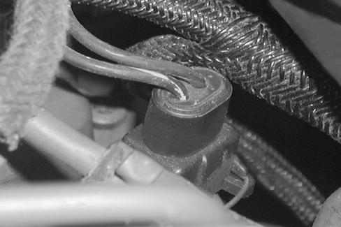
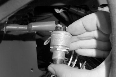
Install the positive (+) test lead to the fuel shut-off solenoid. Turn the key switch to the ON position. The multimeter should read 12 to 13 volts.
If there is no voltage, proceed to the next step.
If there is 12 to 13 volts, but the engine will not start, replace the fuel shut-off solenoid valve.
Check the fuel shut-off solenoid fuse (#2) (1) and test for power to the fuse, refer to (Step 4). Check the ignition relay power (2), refer to (Steps 5 and 6).
If the fuel shut-off fu se and ignition relay are operating properly, repair or replace the red wire between the fuse and the fuel shut-off solenoid.
Template Name: OML_2_col907871E Template Date: 1997_02_12