1 minute read
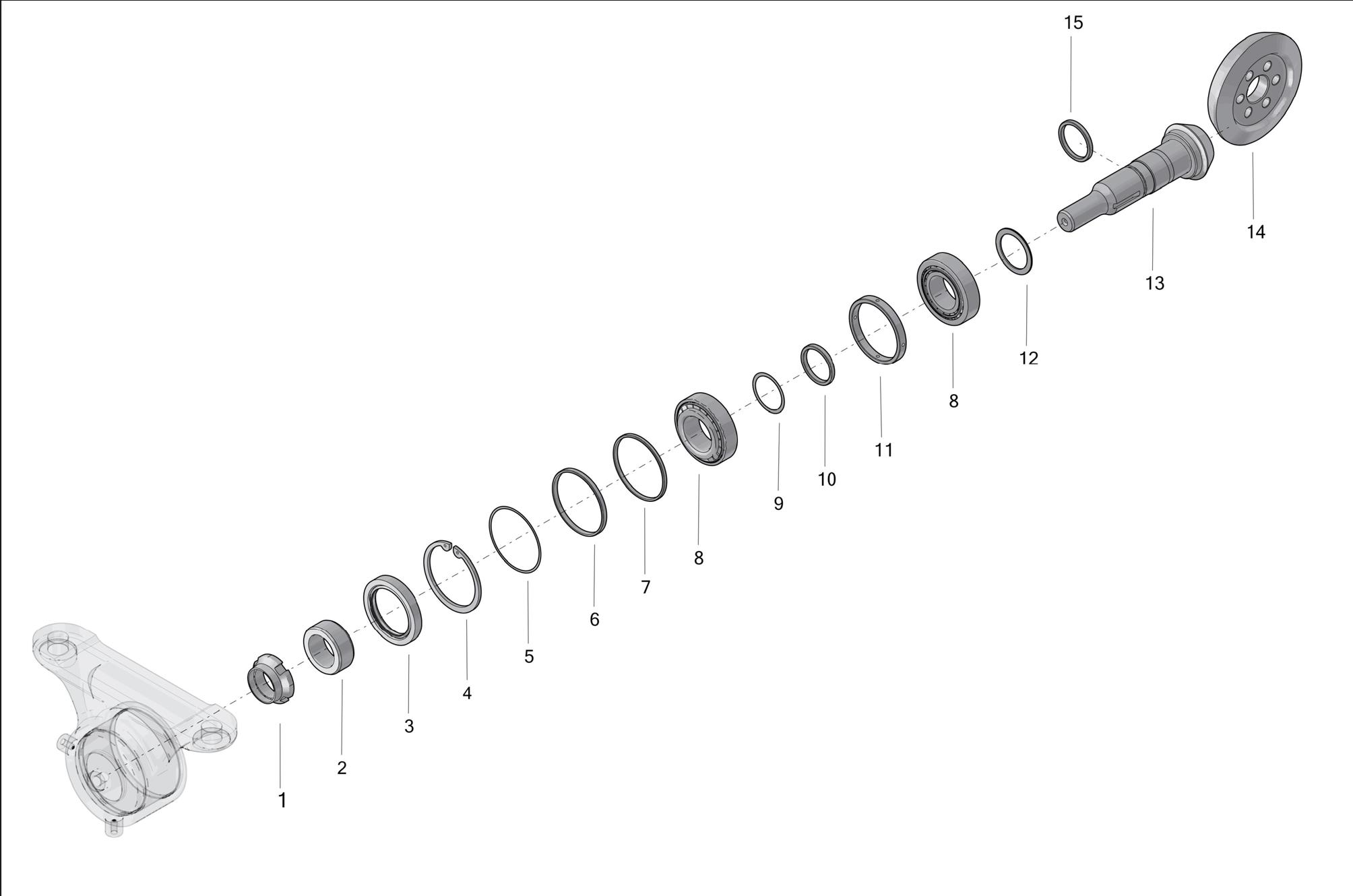
SPLINE SHAFT ASSEMBLY LAYOUT


1
Spline Shaft Assembly Critical Settings

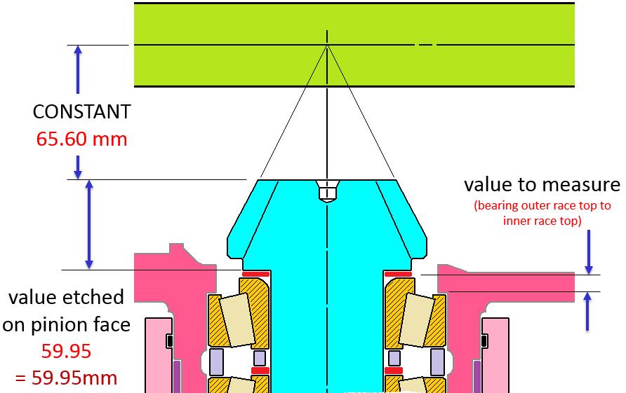
CONE CENTER DISTANCE
As per the value etched on Pinion & bearing height SHIM = CONSTANT –(value etched on pinion face + value to measure)
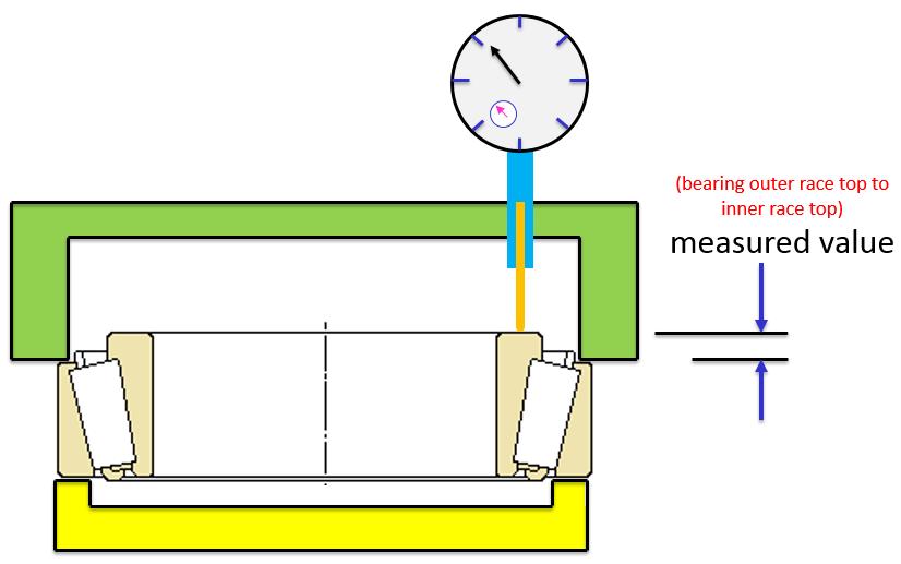
Use special tool for measuring bearing height (bearing outer race top to inner race top)
2
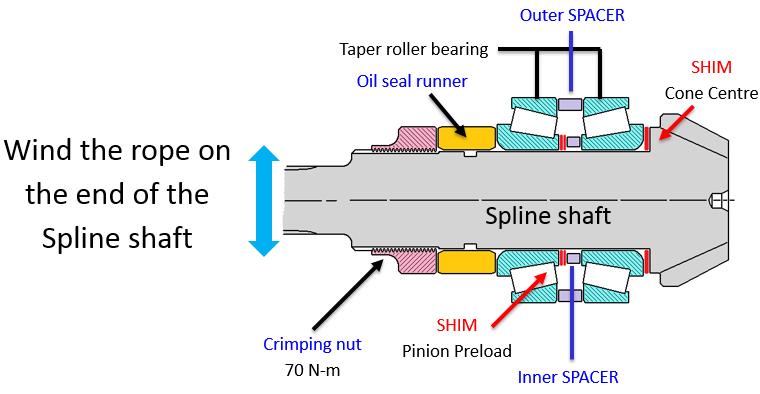
Pinion Bearing Preload
1)Place the CCD shim as per selection.
2)Slide the inner race of the inner taper roller bearing with suitable dolly. Ensuring that the inner race firmly & squarely
3)Place ‘outer race” of the inner bearing, ‘Outer spacer”, Inner spacer few shims, ‘Outer TRB along with outer race, ‘Oil seal runner’ & ‘Crimping nut’. Use suitable pressing dolly.
4)Fix the Spline shaft on FIXTURE. Torque the Crimping nut 70 N-m with a special wrench.
5)Wind the rope on the end of the Spline shaft as shown. Fix the Spring balance on the other end of the rope & measure the pinion bearing preload.
6)Pinion preload should be within 3.0 – 8.0 kg.
*If the Preload is more – add some more shims. *If the Preload is less – remove some shims.
3
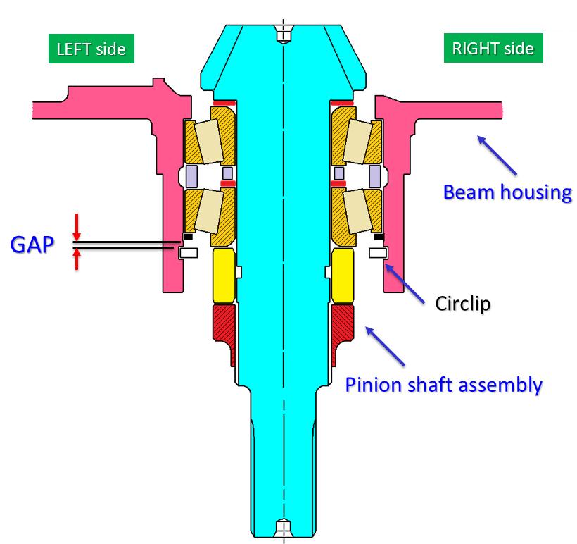
CONE CENTER DISTANCE
1)Measure the gap between ‘Circlip’ & ‘Spacer’ with a FEELER gauge.
2)The gap should be 0.10 mm. Add SHIM to fill the excess gap.
NOTE:-
Ensure free movement of bearing rollers after assembly. Assembly should be free from dust and foreign particles. No Grease should be applied during assembly