
1 minute read
RECOMMENDED FIP MOUNTING INSTRUCTION


1.Make sure to match line on flywheel to hole on flywheel housing
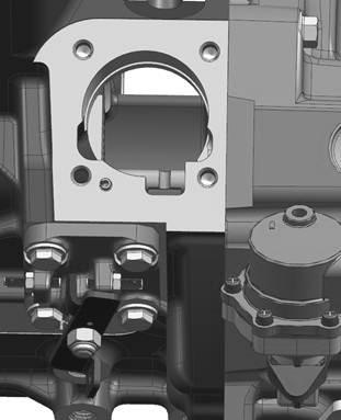
2.Make sure FIP mounting studs and dowel are properly torqued in crankcase,
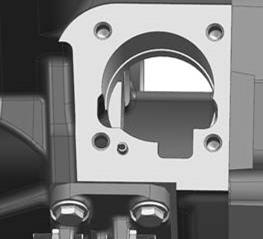
3.Place selected shim assembly (based on the crank case punch mark) on crankcase face making sure all dowels and mounting studs are matched to shim holes.
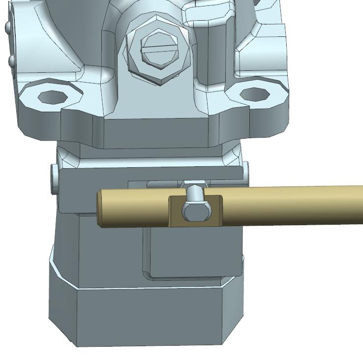
4.Rotate pull to stop lever so that it pushes Control rack rod slot to come in between the slot on crankcase.
5.Place FIP on crankcase and make sure FIP Rack rod position is set to come in between slot of crankcase & Control rack rod.
6.Figure shows how the Pump comes to rests in rack rod after seating on crank case surface .
7.With utmost care gently tap FIP on its flange, so as to get it seated and check pull to stop lever for free actuation.
8.Tighten FIP mounting flange nuts to studs with 25 Nm torque value.
Shim selection
1.Shim thickness used during engine assembly is based on BDC gauge value as per table 2 and is punched on the Crank case surface as shown in fig
2.Shims to be stacked up to match value as punched on crank case, 1 steel shim to be sandwiched in between 2 NBR coated shim.
( BDC gauge dimension in table 2 is given for different shim thickness punched on crank case) .
3.Make sure the FIP flange and Crank case surface is clean and there is no need of liquid sealant to be applied on mounting surface during assembly .