2 minute read
SWIVEL HOUSING SUB ASSEMBLY


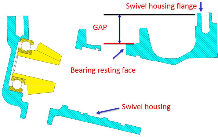
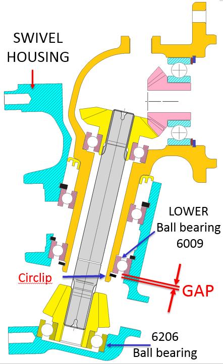
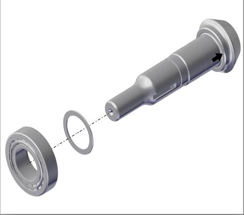
Swivel Housing Sub Assembly Critical Settings
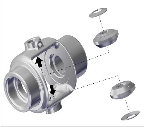
On Swivel housing, measure the GAP from bearing resting face to Swivel housing flange using tool “AGFAYNMG 003” For ExampleMaster height = 35.00 mm Measured reading = - 0.208 mm GAP = 35.000 + 0.204 = 35.208 mm
SIDE HOUSING SUB ASSEMBLY LH & RH
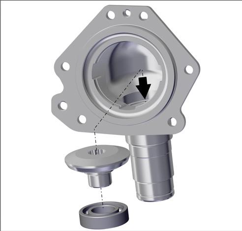
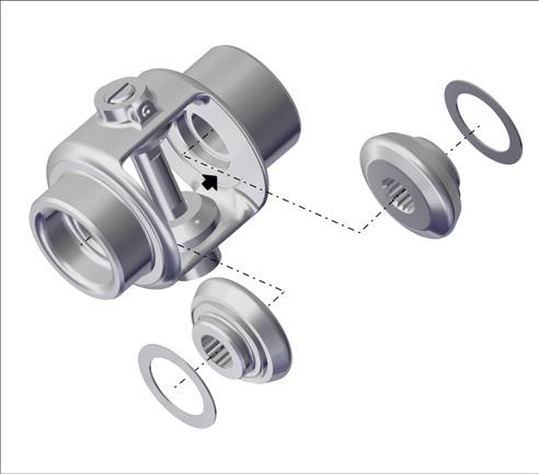
Assemble the Bearing 28X58X16 (006515144Y1) with Bevel Gear Intermediate (006513290Y1) & Assemble it to Side Housing
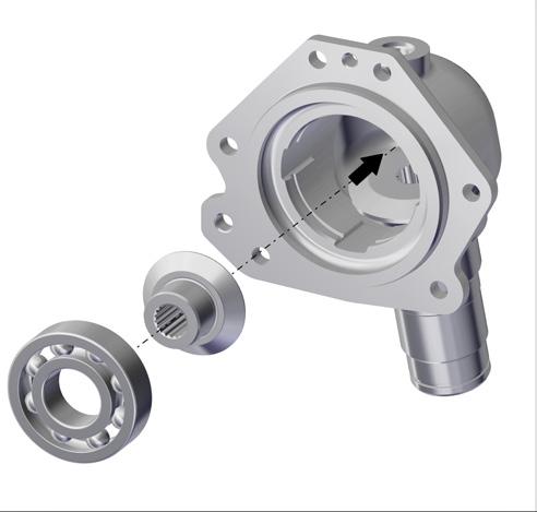
Assemble bearing 35X80X21 (000016299P04) in Bevel Pinion intermediate (006513289Y1). Assemble it to Side Housing
4

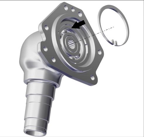
Assemble the Circlip (006505629D1) to Side Housing Inner Groove
Assemble the Spacer (006513385Y1) to Side Housing
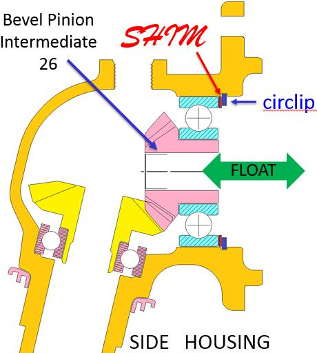
Critical Setting
Measure float of Bevel pinion Intermediate (26) with dial gauge or feeler gauge. Float should be 0.20 mm (maximum). Adjust float with shim
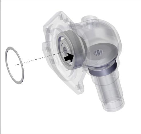
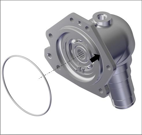
Fit the O-ring (006513337Y1) to Side Housing Outer Groove
Swivel To Side Housing Assembly
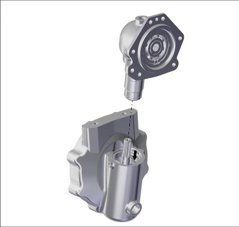
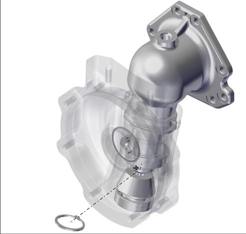
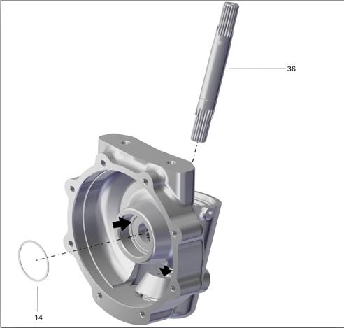
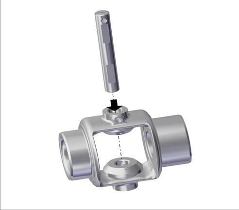
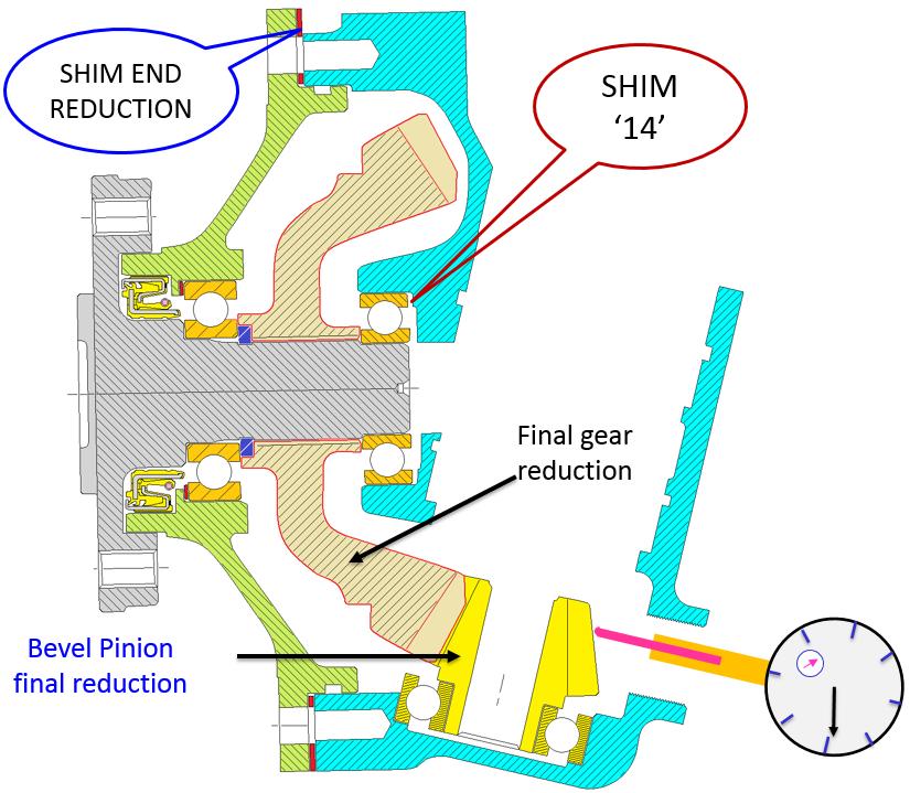
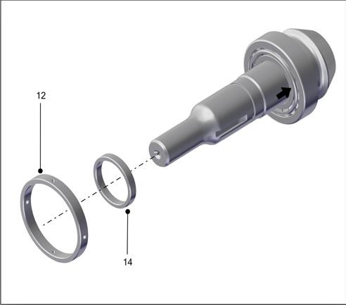
Insert the inclined shaft (33) into swivel housing assembly. Insert the Shim (14) in Swivel Housing
Fitment of circlip (34) on side housing end
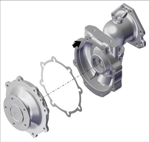
Assemble the side housing sub assembly in Hub Housing sub assembly
Insert the final reduction shims (13) between Swivel and Hub Housing
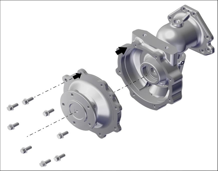
Assemble the Swivel Housing assembly with Hub Housing assembly Torque the bolt (4) Apply Torque 41-50 Nm Transfer of sub assembly to front axle beam housing
Swivel To Side Housing Assembly Critical Settings
NOTE:1
Measure the float (up & down movement) of side housing on swivel housing. It should be within 0.10 – 0.20 mm. Adjust the float with SHIM (0.10 mm / 0.50 mm)
Swivel To Side Housing Assembly Critical Settings
1)When Swivel housing & Hub housing is assembled together there will be a gap. Recommended GAP is 0.200 mm. Hence SHIM ‘14’ will be required.
GAP= Measured Gap- Recommended Gap
2)Assemble Hub housing on Swivel housing with some End Reduction Shims. (do not use the shim ‘14’ at present) Measure the backlash between ‘Final gear reduction’ & ‘Bevel Pinion final reduction with a dial gauge. The backlash should be within 0.13 – 0.23 mm. If not, add shim End Reduction (when the backlash is less) or remove that shim (when the backlash is more).
3)Thickness Of Shim “14”=(GAP+Thickness of Shim End Reduction)
Differential Assembly
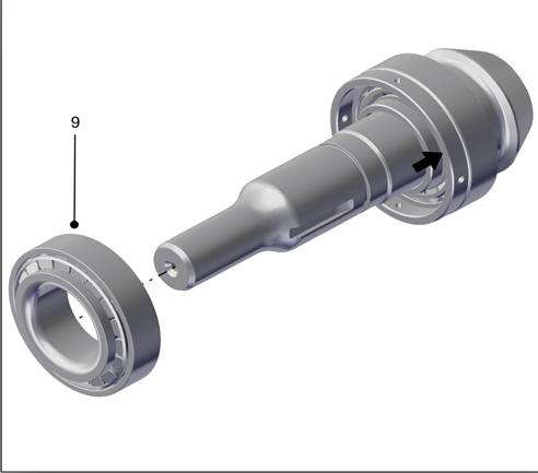
Place the Thrust Washer gear (10) & Pinion Differential (9) in Differential case
Assemble the shaft Differential (11) between the Pinion Differential (9)
Fix the Spring Dowel Pin (12) at Differential Shaft hole to Differential Housing Hole
NOTE:-
Ensure free rotation of differential gears after assembly. Ensure free movement of bearing rollers after assembly. Assembly should be free from dust and foreign particles. No Grease should be applied during assembly
Place the bevel gear thrust washers (7) & gear Differential (8) in differential case
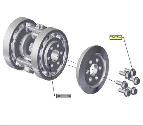
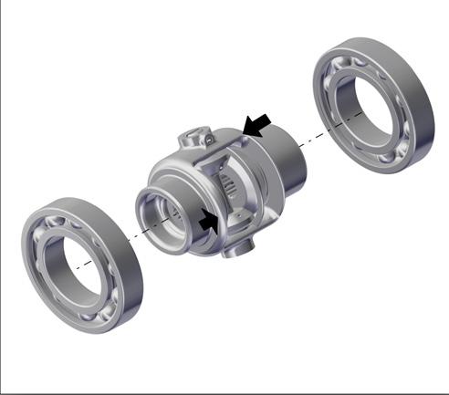
Press the Ball Bearing on both side of Differential Housing (1)
Assemble the Ring gear (5) Differential Housing with Bolt Flange HD M8x1.25x25L (6) Torque 20-27Nm (Use Loctite 638)

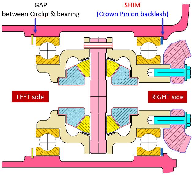
Differential Assembly Critical Settings
1)Measure the gap between circlip & bearing. Gap should be 0.10 mm (maximum). Add SHIM (differential assembly axial float) to adjust the extra gap.
2)Measure the backlash between Crown Wheel & Pinion with a dial gauge. It should be 0.10 - 0.20 mm.
3)If the backlash is not proper (more or less), interchange the position of SHIM (differential assembly axial float) & SHIM (Crown Pinion backlash) to get the desired backlash.
Spline Shaft Assembly
Place the Thrust Washer gear (10) & Pinion Differential (9) in Differential case
1.After assembly of Spline shaft check the Preload Value Pre Load Spec: 3-4Nm.
2.After setting the preload value remove the spacer oil seal
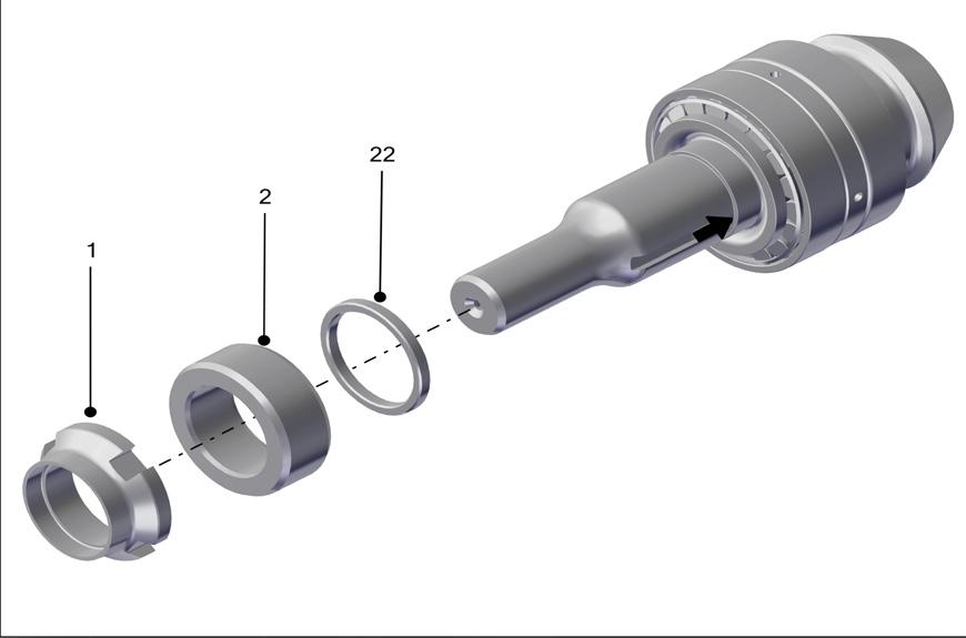
3.Assemble the O-Ring (22) in Spiral Pinion shaft Groove
Assemble the shaft Differential (11) between the Pinion Differential (9)
Fix the Spring Dowel Pin (12) at Differential Shaft hole to Differential Housing Hole
NOTE:-
1.Assemble the Spacer (2) & oil seal (3) in Spline shaft.
2.Assemble the Lock Nut M30x1.5 (1) in Spline shaft.
3.Ensure Torque value (50-70Nm).
4.Crimp the lock Nut in the spline shaft Slot.
Ensure free movement of bearing rollers after assembly. Assembly should be free from dust and foreign particles. No Grease should be applied during assembly