Control and operation
Operating manual
Hydraulic removable counterweight
Extract the pins 7 connecting the telescoping cylinders 1 and the counterweight 2 and fully retract the cylinders.
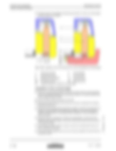
Fig. 3-149 Installation of the connecting pins for main and additional counterweights 1
Telescopic cylinder
2
Counterweight
3 8
Counterweight shell Additional counterweight
7 17
Connecting pin Securing screw
25 27
Pin retaining clamp 26 Mounting screw Retaining clamp for additional counterweight
Installation of the counterweight Place the counterweight 2 beside or behind the track chains so that its bearing points are situated just below the telescoping cylinders 1 (Consider distance X l or X C noticed during removal). Start the Diesel engine and bring it to low idle. Push the lever 5 in direction U for about two minutes to deaerate the hydraulic telescoping cylinders 1. Pull the lever 5 in direction D to extend the cylinders, insert the connecting pins 7 between counterweight 2 and telescoping cylinders 1 and secure the pins 7. Coat the mounting pins 7 with grease before installation, this will facilitate the future removals. Push the lever 5 in direction U to lift the counterweight 2. At the end of the elevation of the counterweight, check that it inserts accurately into the structure of the uppercarriage. Just before the weight comes to contact, insert the mounting bolts 12 and turn them completely in by hand. Lift up the counterweight 2 some more to the stop and tighten the bolts 12 to the prescribed torque.
copyright by
3 - 164
MJFCIFSS
R 974 C / 10069856


