4 minute read
Control and operation


Installing and removing the counterweight
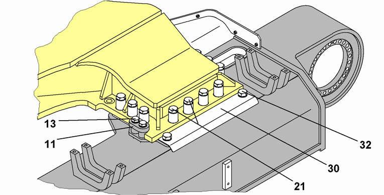
Attach the mounting screws 21, but do not tighten them yet. If all the screws cannot be inserted by hand, then insert first the 2 or 3 mountings screws on the rear or on the front mounting point all the way (but do not tighten them yet) and then move the side frame in or out slightly so that all the screws can be inserted easily.
Tighten all the mounting screws 21 to the specified tightening torque. Grease the uncovered parts of the sliding surfaces on both side frames. Reinstall all the protective covers 30 as necessary. Torque the mounting bolts 32 of the protective covers 30
MachineBolts 32 Class 8.8 - Tightening torque
R944C - R954CM30 - 1350N.m
R964C - R966M36 - 2350N.m
R974C - R976M36 - 2350N.m
3.10Installing and removing the counterweight
3.10.1Installing the lifting accessories on the counterweight
You can lift the counterweight with the two lifting points on the upper face of the counterweight. To access the lifting points, remove the covers 6
2 Centring pins
Installing and removing the counterweight
3 Mounting bolts
6 Cover Danger!
4 Washer
Breakage of the lifting points and falling of the machine! Damages, injuries, death.
Do not use the counterweight lifting points to lift the uppercarriage or the machine.
Use appropriate lifting device and lifting accessories: the angle between the upper face of the counterweight and the slings must be at least 60°.
To select the lifting accessories and lifting device, take into account the weights and lifting forces indicated in the following table.
Machine type - Counterweight weightForce F [kN]Force T [kN]
R 964 C - 11 To 11064
R 964 C - 14,5
R 964 C - 16,5
To14483
To16495
Installing and removing the counterweight
Machine type - Counterweight weightForce F [kN]Force T [kN]
R 974 C - 14 To13880
R 964 C - 16 To15791
3.10.2Removing the counterweight
Danger!
Tipping over of the machine!
Damages, injuries, death.
If the machine is equipped with a special working attachment: Make sure that all necessary working attachment parts are removed.
Remove the stick. Lower the boom onto the ground. Remove the covers 6
Attach the lifting accessories to the lifting points of the counterweight. Loosen and remove the mounting bolts 3 of the counterweight. Prepare appropriate supporting beams on stable and even ground. Use the lifting device to lift the counterweight. Put down the counterweight on the supporting beams. Remove the lifting accessories from the counterweight.
3.10.3Installing the counterweight
Attach the lifting accessories to the lifting points of the counterweight. Check the centring pins 2 for correct position in the bores of the uppercarriage.
Danger!
Falling counterweight!
Damages, injuries, death.
Make sure that no one stands below the counterweight during lifting operations.
Use the lifting device to lift the counterweight.
Put down the counterweight on the uppercarriage so that it fits into the centring pins 2
Engage the mounting bolts 3 with washers 4 and tighten to the appropriate torque. See Chapter 5: "Mounting bolts of the counterweight".
Attention!
Damages to the steel construction structures!
Before starting the machine, make sure that all the mounting bolts of the counterweight are installed and tightened to the appropriate torque.
Remove the lifting accessories.
Hydraulic removable counterweight
Reinstall the covers 6
3.11Hydraulic removable counterweight
This optional equipment makes it possible to let down and lift the counterweight of the machine quickly and without needing an additional lifting device (as an example to make the conveyance easier). This is achieved via two telescoping cylinders and using the hydraulic power of the machine.
3.11.1Safety guidelines for lifting and lowering the counterweight
Danger!
In order to maintain the stability of the machine, a part of the working attachment is to be removed before lowering the counterweight.
As a basic rule we recommend to remove all the attachment parts with exception of the boom (gooseneck boom, main boom or shovel boom) and to lower the boom to the ground.
Before attempting to lower or to raise the counterweight, always check that the mounting pins 7 are mounted and fully engaged in their bores. Never stand below the counterweight during its down or up motion and as long as it is not properly secured with its fastening screws.
Hydraulic removable counterweight
3.11.2Removal and lifting up of counterweight
Level controlling the up and down movements
The control lever 5 is mounted directly to the control valve 6 situated on the rear of machine between hydraulic pumps and counterweight shell 3. It is accessible after opening the right rear side door 4
–Push the lever 5 towards "U" to lift the counterweight Up.
–Pull the lever 5 towards "D" to let the counterweight Down.
Caution!
Depending on the machine type, the model of the undercarriage and the carrying out of a possibly mounted additional counterweight, the counterweight assembly may run into the track chains if stroke down to the ground with the uppercarriage lenghtwise.
Before removal, check if this applies or not. If it does, the counterweight has to be removed either crosswise down to the ground level, or lenghtwise down to supports having adequate height.
Removal of the additional counterweight (as necessary)
Start the Diesel engine and bring it to low idle.
Push the lever 5 in direction U for about two minutes to deaerate the hydraulic telescoping cylinders 1
Lift up the counterweights and loosen and remove the fastening bolts 18 of the additional counterweight 8.
Pull the lever 5 in direction D to let the additional counterweight 8 down to the ground level or to the installed wooden supports.
Loosen the securing screws 17 and extract the pins 7 connecting the telescoping cylinders 1 and the counterweight 2 and fully retract the cylinders.
Notice!
The pin retaining clamps 27 do not need to be removed from the additional counterweight 8
Fully retract the telescoping cylinders 1.
Loosen the screws 26 and remove the pin retaining clamps 25 which are attached to the front face of the additional counterweight 8
Attach the retaining clamps to the lower face of the counterweight 2, in the area of the pass for the telescoping cylinders 1 and fix them using the screws 26
Tighten the screws 26
Carefully extract the telescoping cylinders 1 so to insert the eye of the piston rod between the retaining clamps 25 already fixed to the counterweight.
Insert the connecting pins 7 between the telescoping cylinders 1 and the counterweight 2 and secure the pins 7 using the screws 17.
Removal of the counterweight
Start the Diesel engine and bring it to low idle.
Push the lever 5 in direction U for about two minutes to deaerate the hydraulic telescoping cylinders 1
Lift up the counterweight 2 and loosen and remove its fastening screws 12 copyright by
Pull the lever 5 in direction D to let the counterweight 2 down to the ground level or to previously disposed wooden supports.
Danger!
Only lower the counterweight to level, solid and horizontal ground. If necessary, fit the deposit surface with wooden blocks.
Notice the distance X l or X C between track chain and front face of the counterweight for later installation.