81 minute read
5.2Cleaning machine


The machine should be cleaned before carrying out any maintenance or repair work. In particular, the connections and screws should be cleaned of oil, fuel and residue of cleaning agents.
Note!
High-pressure water jet cleaners (steam cleaners) can damage the coating.
Do not use high-pressure water jet cleaners during the first two months after commissioning (or after recoating).
Observe the prescribed safety distances.
Before cleaning the machine:
Before cleaning the machine with water or with a steam cleaner (high-pressure water jet cleaner), carry out the following tasks to protect the equipment against penetrating water.
Lubricate all bearing points, bolt connections and the slewing ring; if necessary, use the central lubrication system to do this.
Cover or seal all openings that must be protected against penetrating water for safety reasons (particularly at risk of damage are electric motors, electric components, switch cabinets, plug connections, measuring sensors and air filters).
Cleaning:
Use flint-free cleaning cloths.
Do not use aggressive detergents or flammable liquids.
When cleaning the engine compartment, ensure that the temperature sensor of the fire alarm and extinguishing systems (if installed) are not accidentally brought into contact with the hot cleaning solution,
After cleaning:
Remove all seals and covers.
Check all fuel, engine oil and hydraulic lines for leakage, loose connections, chaffing and damage.
Repair any defects without delay.
Lubricate all bearing points, pin connections and the slewing ring to remove any water that might have been penetrated.
If required, renew the preservation layer (anti-corrosion protection) on components and surfaces.
5.3Care for rubber components
The service life of rubber seals can be prolonged by treating them with a rubber care product.
Clean and regularly treat the rubber seals on doors and panelling elements with a care product. This helps prevent premature wear and protects the rubber seals during the cold season.
Recommended care products: Silicone, talcum powder, deer tallow
5.4Lubricants and fluids
5.4.1General information
Observe the instructions for lubricants and process chemicals. Lubricate the machine and change the oils at the prescribed intervals. For more information, see lubrication chart and inspection and maintenance schedule. Keep workplaces for these activities clean. This enhances the service life and reliability of the machine.
All work on the machine must be carried out while it is standing on firm and level ground.
Switch off the diesel engine, remove the ignition key and set the battery main switch to position 0 (OFF).
Clean lubricating nipples before adding grease. Clean all filling points and the area around them before opening the caps and screws.
The oil should be changed while it is at operating temperature. After each oil change or refilling, check the fill level in the respective unit (the specified fill levels are guide values).
Collect old oil and chemicals in suitable containers and dispose of them according to the applicable statutory regulations.
5.4.2Filling quantities and lubricating chart
Recommended
* = guide values
Recommended fuels and chemicals
* = guide values
SymbolDescription
For oil change intervals, observe the relevant instructions in the operating manual.
Medium filling point
Slewing gear mechanism
Travel gear mechanism
Pump distributor gear
Gearbox or axle, check oil level
Diesel engine, check oil level
Hydraulic tank, check oil level
Lube point
Lubricate machine
Tab. 5-1
5.5Lubricants and fluids specification
5.5.1Diesel fuels Specification
The diesel fuels must meet the minimum requirements of the fuel specifications outlined below.
Approved specifications:
–DIN EN 590
–ASTM D 975 (89a) - 1D and 2D
The fuel supplier must submit a fuel certificate (fuel specification, sulphur content, lubricity, cetane number)
Sulphur content, lubricity
The following restrictions apply:
–Do not use fuels with a sulphur content of more than 1% (10,000 mg/kg).
–When using engine oils conforming to specification E6 and standard oil change intervals (every 500 operating hours): Do not use fuels with a sulphur content of more than 0.005% (50mg/kg).
–When using exhaust gas purification units (particle filters): Do not use fuels with a sulphur content of more than 0.005% (50mg/kg).
–Diesel engines with external exhaust gas return system: We recommend using fuels with a sulphur content of less than 0.005% (50 mg/kg).
Additional information: see oil change intervals for operation under adverse conditions.
According to DIN EN 590, diesel fuels must have a lubricity determined by HFRR test (corrected wear scar diameter [wsd 1.4] at 60°C) of maximum 460µm
The ASTM D 975 fuel standard does not specify that the fuels must undergo a fuel lubricity test. The required additives should be added by the supplier, who is responsible for the quality of the fuel.
Cetane number
ASTM D 975 fuels must have a cetane number of minimum 45. A cetane number of more than 50 is preferable, especially at temperatures below 0°C (32°F).
Low temperature operation
At low temperatures, paraffin crystals are formed in the diesel fuel. They increase the flow stress in the fuel filter so that the diesel engine might not be supplied with sufficient fuel.
Caution!
The use of an unsuitable fuel can cause damage to the diesel engine. Adding petroleum, normal car petrol or other substances damages the injection system. Never add petroleum, car petrol or other additives to the diesel fuel. At ambient temperatures of below -20°C: use start-up aid (e.g. fuel filter heater). For operation of the machine under arctic conditions: use special diesel fuels that offer adequate viscosity.
5.5.2Lubricating oil for the diesel engine Quality
Modern diesel engines must be lubricated with high-performance oils. They consist of a basic oil with special additives.
The lubricating oil requirements for LIEBHERR diesel engines are based on the following standards and regulations:
DesignationSpecification
ACEA classification (Association des Constructeurs Européens d'Automobiles)
API classification (American Petroleum Institute)
Tab. 5-2 Lubricating oil specifications
E4, E6, E7
Caution: particle filter only permitted with E6
CH-4, CI-4
Caution: observe shorter oil change intervals
If LIEBHERR oils are not available locally, use an oil that conforms to the specifications (before choosing an oil, contact our customer service department).
Viscosity
The choice of the lubricating oil viscosity is based on the SAE classification (Society of Automotive Engineers). The SAE classification does not provide any indication as regards the quality of a lubricating oil. The relevant factor for the correct choice of SAE class is the ambient temperature.
Excessively high viscosity might lead to start-up problems. If the viscosity is too low, the oil's lubrication might not be sufficiently efficient.
The temperature ranges shown in the diagram are approximate ranges that might temporarily be exceeded.
5-5 Temperature-based selection of the SAE class
For ambient temperatures of -20°C (-4°F) to +45°C (+113°F), we recommend the following diesel engine oils:
Liebherr Motoroil 10W-40, specification ACEA E4
Liebherr Motoroil 10W-40 low ash, specification ACEA E6
For ambient temperatures of -30°C (-22°F) to +15°C (+59°F), we recommend the following diesel engine oils:
Liebherr Motoroil 5W-30, specification ACEA E4
Liebherr Motoroil 5W-30 low ash, specification ACEA E6
Adverse operating conditions affecting the oil change intervals
Oil change intervals: see chapter "Inspection and maintenance schedule".
Subsequent oil changes depend on the climate, the sulphur content of the fuel and the oil grade. For details, see the table below.
If the specified operating hours (h) per year are not reached, the diesel engine oil and the filter must be changed at least once every year.
A number of adverse factors (unfavourable operating conditions) affect the length of the maintenance interval. Possible adverse factors: –Frequent cold starts –Sulphur content of fuel –Operating temperature
If such factors apply, the oil and filter must be changed according to the table below.
Adverse factorOil quality
CH-4, CI-4E4 / E7*
Operating conditionsSulphur content of fuelInterval
Normal climate, to -10°Cto 0.5%250h500h between 0.5% and 1%125h250h below -10°Cto 0.5%125h250h between 0.5% and 1%not permissible125h
Adverse factorOil quality
E6
Operating conditionsSulphur content of fuelInterval
Normal climate, to -10°Cto 0.005%500h between 0.005% and 0.05%250h between 0.0501% and 0.1%125 h below -10°Cto 0.005%250h between 0.005% and 0.05%125h between 0.0501% and 0.1%not permissible h= operating hours
* TBN minimum 13mg KOH/g
5.5.3Coolants for diesel engine
General recommendations
The cooling system works only properly when pressurised. It is therefore imperative that it is kept clean and sealed at all times, that the radiator sealing and operating valves work properly and that the required coolant level is maintained.
Corrosion inhibitors/antifreeze agents approved by LIEBHERR ensure proper protection against frost, corrosion and cavitation without causing damage to seals and hoses and without foaming.
Coolants that contain unsuitable corrosion inhibitors or antifreeze agents or that have been prepared incorrectly might cause failure of assemblies and component parts in the coolant circuit due to cavitation or corrosion. Heat-insulating deposits on components that conduct heat might result in overheating and consequently failure of the engine.
Water (fresh water)
Clear and clean water free of particles that meets the following chemical requirements is suitable for use as a coolant. Do not use sea water, brackish water, brine or industrial wastewater.
DesignationValue / unit
Total alkaline earth metals (water hardness) 0.6 to 3.6 mmol/l (4 to 25°e) pH at 20°C6.5 to 8.5
Chloride ion concentrationmax. 80 mg/l
Sulphate ion concentrationmax. 100 mg/l
DesignationValue / unit
Total alkaline earth metals (water hardness) 0.6 to 2.7 mmol/l (4 to 19°e) pH at 20°C6.5 to 8.0
Chloride ion concentrationmax. 80 mg/l
Sulphate ion concentrationmax. 80 mg/l
* = Diesel Coolant Additives
Water analysis results are available from the local authorities.
Mixing ratio for coolant
The coolant must contain min. 50% corrosion inhibitor and antifreeze agent at all times of the year
A Ambient temperature
B Corrosion inhibitor/antifreeze agent concentration in coolant
Permissible corrosion inhibitors/antifreeze agent
Note!
Improper mixing of different products might negatively affect the properties of the coolant and cause damage to the cooling system.
Use only approved products. Do not mix different products.
Never mix products containing silicone with silicone-free products.
If the recommended LIEBHERR product is not available locally: Contact the LIEBHERR customer service department; choose product conforming to the "Coolant specifications for LIEBHERR diesel engines".
TypeDescription
ConcentrateLiebherr Antifreeze Concentrate
Liebherr Antifreeze OS Concentrate
PremixLiebherr Antifreeze Mix
Liebherr Antifreeze OS Mix
Tab. 5-6
Permissible corrosion inhibitors/antifreeze agent containing silicate from Liebherr
Premix = ready-mixed product (50% water and 50% corrosion inhibitor/antifreeze agent)
Approved corrosion inhibitors without antifreeze agent
Note!
Improper mixing of different products might negatively affect the properties of the coolant and cause damage to the cooling system.
Use only approved products. Do not mix different products. Never mix products containing silicone with silicone-free products.
If the recommended LIEBHERR product is not available locally: Contact the LIEBHERR customer service department; choose product conforming to the "Coolant specifications for LIEBHERR diesel engines".
In exceptional circumstances and at ambient temperatures that are always above the freezing point, e.g. during use in tropical regions where there are no corrosion inhibitors/antifreeze agents available, the following inhibitors must be added to the coolant:
–DCA 4 (Diesel Coolant Additives 4)
–Caltex / Chevron / Havoline / Total product
In this case, the coolant must be changed annually.
As part of routine maintenance work, check the concentration and correct it, if necessary.
Product nameManufacturer
DCA 4 Diesel Coolant AdditivesFleetguard / Cummins Filtration
Caltex CL Corrosion Inhibitor ConcentrateChevron Texaco
Chevron Heavy Duty Extended Life Corrosion Inhibitor Nitrite Free (ELC) Chevron Texaco
Havoline Extended Life Corrosion Inhibitor (XLI)Chevron Texaco
Total WT SupraTotal, Paris
5.5.4Hydraulic oil
Hydraulic oils must meet the requirements given below.
Maximum water content of hydraulic oil: <0.1%
Liebherr hydraulic oil
Liebherr recommends using the following hydraulic oils in its machines (depending on temperature range):
A Ambient temperature
B Cold-start range with warm-up instruction
C Operating range
Liebherr Hydraulic Plus and Liebherr Hydraulic Plus Arctic are applicable for both long-term use and use in environmentally sensitive areas.
If Liebherr oils are not available locally, use one of the engine oils listed in section "Engine oils for use as hydraulic oils". Before choosing an oil, contact the Liebherr customer service.
Engine oils for use as hydraulic oils
When using engine oils (third-party products) as hydraulic fluids, request a certificate from the oil manufacturer, confirming that the product meets the following specifications.
Engine oils used as hydraulic oils must meet the following specifications:
Single-grade oils (1) API - CD / ACEA - E1 (MB 226.0 and 227.0)
Multigrade oils (2) API - CD, CE, CF / ACEA - E2, E3, E4 (MB 227.5, 228.1, 228.3 and 228.5)
A Ambient temperature
B Cold-start range with warm-up instruction
C Operating range
1 Single-grade oils
2 Multigrade oils
*for deviating viscosity grade, contact the Liebherr customer service.
Warm-up instructions
The black bar B indicates ambient temperatures that are up to 20°C below the operating range C
For cold starting at an ambient temperature below range B, the following warm-up instructions for the hydraulic oil apply:
1. Start the Diesel engine and set it to medium speed (not exceeding 50% of maximum speed).
2. Carefully activate the working hydraulics. Operate the hydraulic cylinders and move them briefly to the stop.
3. After approximately 5 minutes, start the travel hydraulics. The total warm-up time is approximately 10 minutes.
For cold starting at lower ambient temperatures: Before starting the engine, warm up the hydraulic oil tank. Then follow warm-up instructions 1 to 3
Biodegradable hydraulic oil
Caution!
Do not mix hydraulic oil products!
When mixing different ester-based biodegradable hydraulic oils or mixing such products with mineral oils, aggressive chemical reactions might occur, causing damage to the hydraulic system.
Do not mix biodegradable hydraulic oils from different producers. Do not mix biodegradable hydraulic oils with mineral oils.
Depending on the temperature range, Liebherr recommends the following hydraulic oils for the machine:
Liebherr Hydraulic Plus or Liebherr Hydraulic Plus Arctic
When using these hydraulic oils, bypass filtration is not mandatory.
If these oils are not available locally, use fully saturated hydraulic environmental ester synthetic (HEES) fluids. Before choosing an oil, contact the Liebherr customer service.
Caution!
The use of synthetic ester-based oils without a bypass filter causes damage to the hydraulic system!
If synthetic ester-based oils are used, bypass filtration is mandatory, in order to maintain the water content in the oil below 1000ppm (0.1%).
Use a bypass filter (optional equipment).
When using such fluids, we recommend replacing the hydraulic hoses every 4000operating hours or at least every 4 years.
Do not use vegetable oils, as they do not possess the necessary thermal stability. Under certain circumstances, the use of polyglycols is permitted, although they can cause damage to seals or the paintwork. Do not use oils containing polyglycols without first consulting the Liebherr customer service.
When using third-party products, request a certificate from the oil manufacturer, confirming that the product meets the above specifications.
Oil change, oil analysis and filter change
Oil change
Note!
Liebherr recommends carrying out regular oil analyses. See "Oil analysis".
Oil change
Oil type
LIEBHERR mineral oil
Liebherr Hydraulic HVI
Liebherr Hydraulic Basic 68
Liebherr Hydraulic Basic 100
Liebherr-PAO**
Liebherr Hydraulic Plus
Liebherr Hydraulic Plus Arctic
Not for use in environmentally sensitive areas For use in environmentally sensitive areas (only permissible with oil analysis*) without oil analysis with oil analysis* (optional) every 3000 hevery 6000 h- *** every 4000 hevery 8000 hevery 8000 h
Third-party product - mineral oilevery 2000 hevery 2000 h- ***
Third-party product - fully saturated synthetic ester - ***- ***every 2000 h
Tab. 5-8 Oil change intervals
*If the result of the oil analysis is satisfactory, you may continue using the oil for a longer period. If the result of the oil analysis is negative, immediately change the oil.
**PAO = polyalphaolefin
***not permissible
Use in environmentally sensitive areas: machines operated in such areas must be filled with biodegradable hydraulic oil.
If the machine is operated for less than 1000 hours per year, an oil sample must be taken at least once a year. If a hydraulic oil remains in the machine for a prolonged period of time, it must be changed at least every 4 years (mineral oils and fully saturated synthetic esters) or every 6 years (Liebherr-Plus oils).
If the machine is not in use for a period of more than 6 months, carry out an oil analysis before restarting it.
Oil analysis
For regular oil analyses, LIEBHERR recommends contracting the specialist company OELCHECK and changing the oil when indicated by the test results in the lab report.
–Yellow kit for biodegradable hydraulic oils
–Green kit for mineral oils
See also customer service and product information.
Reasons for regular oil analyses:
–Reduction of costs thanks to prolonged oil change intervals
–Detailed information regarding the hydraulic system, its components and the medium
–Better protection of resources and the environment
Lubricants and fluids specification
Oil sampling / operating conditions
Oil sampling in machines operated under normal operating conditions
Oil sampling in machines operated under extremely dusty conditions
The oil sampling interval is determined by the actual operating conditions (for more information, see chapter "Dust-intensive applications, reduction of oil contamination").
Tab. 5-9 Symbols: Oil sampling depending on operating conditions
Oil sampling
Not for use in environmentally sensitive areas (oil analysis optional)
For use in environmentally sensitive areas (oil analysis mandatory)
Oil type
LIEBHERR mineral oil
Liebherr Hydraulic HVI
Liebherr Hydraulic Basic 68
Liebherr Hydraulic Basic 100
Liebherr-PAO*
Liebherr Hydraulic Plus
Liebherr Hydraulic Plus Arctic every 1000 hevery 250 h- **- ** every 1000 hevery 250 hfirst at 0 h, then every 1000 h first at 0 h, then every 250 h
Third-party product - mineral oil first at 1000 h, then every 500 h every 250 h- **- **
Third-party product - fully saturated synthetic ester - **- **first at 0 h, then every 500 h first at 0 h, then every 250 h
Tab. 5-10 Oil sampling depending on operating conditions
*PAO = polyalphaolefin
**not permissible copyright by
Filter change
Filter change / operating conditions
Filter change in machines operated under normal operating conditions
Filter change in machines operated under extremely dusty conditions
The filter change interval is determined by the actual operating conditions (for more information, see chapter "Dust-intensive applications, reduction of oil contamination"). Change of return filter (use only LIEBHERR filters) every 1000 hevery 500 h
Change of bypass oil filter
LIEBHERR filterFilters from other manufacturers every 2000 h or as indicatedevery 500 hevery 250 h
Dust-intensive applications, reduction of oil contamination
If the machine is regularly operated with a hydraulic hammer or under similar conditions (very dusty environment), the hydraulic oil can become more contaminated than under normal working conditions.
To prevent premature wear of the hydraulic components, the oil change and sampling intervals must be shortened.
Observe the following:
–The filter cartridge(s) in the return filter must be replaced every 500operating hours and after every hydraulic oil change.
–Use 10-µm filter cartridges instead of the standard 20/5-µm cartridges.
–The 2-µm breather filter must be replaced every 500operating hours and after every hydraulic oil change.
Machines delivered with a hydraulic hammer attachment and retrofitted hydraulic hammer kits are already equipped with 10-µm filter cartridges in the return filter. Please take this into account when ordering spare parts.
5.5.5Lubricants for gearboxes
Quality
Recommended lubricant
Specification
Liebherr Gear Basic 90 LSAPI: GL-5
MIL-L: 2105 D
ZF: TE-ML 05C, 12C, 16E, 21C
Liebherr Gear Plus 20W-40API: Niveau von GL4
ZF: TE-ML 05F, 06K, 17E
Liebherr Gear Hypoid 90 EPAPI: GL 5
MIL-L: 2105 B, C, D
ZF: TE-ML 05A, 12A, 16C, 17B, 19B
Liebherr Hypoid 85W-140 EPAPI: GL-5
MIL-L: 2105 D, PRF-2105 E
ZF: TE-ML 05A, 07A, 16D, 21A
Liebherr Hydraulic-Gear ATFGM: Dexron II D
ZF: TE-ML 03D, 04D, 11A, 14A, 17C
Liebherr Syntogear Plus 75W-90API: GL-4, GL-5, MT-1
MIL-L: 2105 D, PRF-2105 E
ZF: TE-ML 02B, 05B, 07A, 12B, 16F, 17B, 19C, 21B
Tab. 5-14 Lubricating oil specifications
If LIEBHERR oils are not available locally, use an oil that conforms to the specifications (before choosing an oil, contact our customer service department).
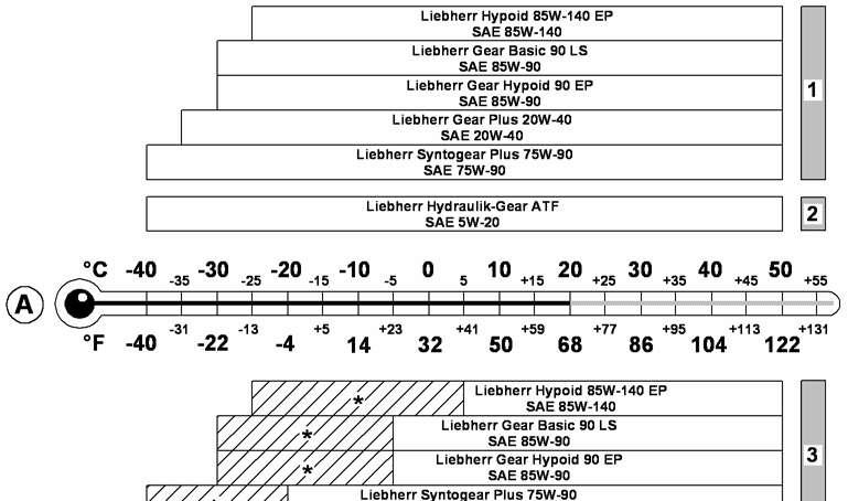
Viscosity
Fig. 5-9
Temperature-based selection of the SAE class
A Ambient temperature
1 Use in gearboxes
2 Use in automatic transmissions
3 Use in pump distributor gear systems
* If the pump distributor gear is equipped with an oil cooler, the oil is not suitable for the marked temperature range (shaded area).
The choice of the lubricating oil viscosity is based on the SAE classification (Society of Automotive Engineers). The SAE classification does not provide any indication as regards the quality of a lubricating oil. The relevant factor for the correct choice of SAE class is the ambient temperature. Incorrect viscosity can impair the operation of axles and gearboxes.
The temperature ranges shown in the diagram are approximate ranges that might temporarily be exceeded.
5.5.6Grease Quality
Recommended lubricantSpecification
Liebherr Universalfett 9900Soap-base grease (lithium complex)
KPF 2 N - 25 (DIN 51502)
NLGI grade: 2 (DIN 51818)
VKA welding force: > 6000 N (DIN 51350 / 4)
Liebherr Universalfett Arctic (for lowtemperature operation)
Soap-base grease (lithium complex)
KPFHC 1 N - 60 (DIN 51502)
NLGI grade: 1 (DIN 51818)
VKA welding force: > 5500 N (DIN 51350 / 4)
Liebherr Spezialpaste CRL*NLGI grade: 2 (DIN 51818)
VKA welding force: > 5500 N (ASTM D2596) water resistance: 1-90 (DIN 51807).
* Only use the Liebherr Spezialpaste CRL for the swing ring teeth
The grease is used for both automatic and manual machine lubrication. it is supplied by the central lubrication system or through lubrication nipples to the respective lube points.
Examples:
–Slewing ring bearings
–Crown gears, geared wheels
–Attachments
Operating temperature
Fig. 5-10 Operating temperature for Liebherr greases
A Grease temperature
* The grease is not suitable for the temperature range (shaded), if used in a central lubrication system.
** The grease may only be within the temperature range (shaded) for short periods of time. Peak temperatures of max. 200 °C (392 °F) are possible.
5.5.7Lubricants and care products for electrical and mechanical components
Medium, purposeProduct (manufacturer)
Contact spray for slip ringsCramolin
Lubricant for pistons, piston nuts and for the mounting of piston rod bearings at hydraulic cylinders
Special corrosion inhibitor for mounting recesses of sealing elements at hydraulic cylinders
5.6Diesel engine
Danger !
Before carrying out diverse maintenance tasks, the Diesel engine, unless otherwise expressly specified in the descriptions, must be brought into the below describedmaintenance position :
–the Diesel engine must be positioned horizontally, –the Diesel engine must be turned off, –the Diesel engine must be cooled off, –the battery main switch must be switched off.
5.6.1Checking the oil level in the Diesel engine
Danger!
Risk of burning.
The engine oil is hot when it is at or near operating temperature. Do not allow the hot oil or oil-bearing parts to touch the skin.
The machine must be standing level. Turn the engine off. Wait a few moments for the oil to collect into the engine oil sump.
Oil dipstick 1 and oil filler neck 2
Pull out the dipstick 1, clean it and reinsert it into its orifice.
Pull out the dipstick again and now notice the oil level. The oil level must be between the min and max marks of the dipstick 1. If necessary, add oil via the filler neck 2 until having the correct oil level.
5.6.2Replacing the engine oil and the engine oil filter elements
Note!
Only carry out the engine oil change when the oil is warm
To drain the oil: The two engine oil filter units are mounted to the Diesel engine, on the cooler fan side.
Unscrew the both filter covers 11 until the upper O-ring 12 becomes visible. The engine oil contained in the filter units flows back into the engine oil sump. Unscrew the plug of the drain valve which is situated on the engine oil sump.

Connect the drain hose supplied with the machine to the drain valve on the sump. Collect the escaping oil into a suitable container. Remove the drain hose and reattach the plug of the drain valve.
Replacing the oil filter elements:
Danger!
Be careful to avoid contact with hot oil when removing the filter cartridges 14
Go on unscrewing the both filter covers 11 and remove them complete with the filter elements 14
Draw the filter elements 14 away from the covers 11.
Notice !
On the machines delivered before Mai 2010, the filter cover 11 and the guiding tube 15 consisted of two separable parts. These separable covers have been basicaly replaced at customers at the latest before end of December 2010 by covers in non separable monobloc execution.
Should you, passed this date, notice during removal of a cover 11, that the guiding tube 15 remains in the filter element 14:
Pull the guiding tube 15 out of the filter element 14 et reinsert it into the cover 11
Immediately report this statement to the responsible for the machine maintenance in order to initiate as soon as possible the replacement by covers in monoblock execution (as per the Service Information LFR 04-53-13 / 10).
Dispose of the old filter elements 14 for their elimination in conformity with the respect of the environment
Slightly coat new O-rings 12 and 13 with oil and install them. Install the new filter elements 14 onto the covers 11.
Reinsert the oil filter covers 11 previously assembled with the elements 14 into their housings and retighten (tightening torque is 40+10 Nm - 30+7 ft.lbs).
Refilling the Diesel engine with oil:
Add the oil via the filler neck 2 until the oil level is between the min and max marks of the dipstick 1
Clean the filler plug and reinstall it to the filler neck 2
Start the Diesel engine.
Check the oil pressure indication on the monitoring display of the machine and check the oil filter covers 11 for leaks.
Turn the Diesel engine off.
Wait for 2 or 3 minutes and check the oil level again. For oil quantity and oil quality see the lubricants chart. For the oil change intervall, see the maintenance chart.
5.6.3Polyvee belt for the airco compressor and alternator drive
The Diesel engine is fitted with a tensioning device for the belts. This device is selftensioning and is therefore maintenance-free.
Regularly check the belt for damage and wear and replaced it if necessary. The following damages to the belt make its replacement necessary:
–Rib fractures
–Transversal fractures in several ribs
–Rubber nodules in between the ribs
–Deposition of dirt or stones
–Ribs becoming loosened at the base of the ribs
–Transversal fractures on the belt exterior
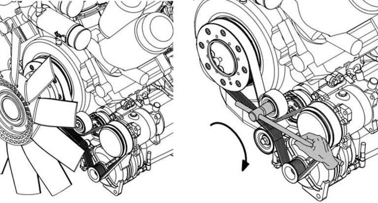
5-15 Replacing the belt
To replace the belt:
To replace the belt, you will need a spinner wrench with hexagon socket. Rotate the tensioning device back against the spring force clockwise as far as the stop.
Remove the worn belt.
Check tension pulley and belt pulley for sound condition (e.g. worn bearing of tension pulley, as well as wear of the belt pulley profile)
If parts are damaged, replace the parts.
With the tensioning device rotated back against the spring force, lay a new belt on the pulleys for the crankshaft, airco compressor, alternator and on tensioning and deflection pulleys.
Swing the tensioning device back counterclockwise into the tensioning position.
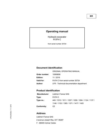
5.6.4Checking mounting bolts
Fig. 5-16 Mounting bolts
Check at regular intervalls, as requested in the maintenance chart the correct mounting (tightening torques) of the thereafter listed bolts. Retighten the screws as necessary.
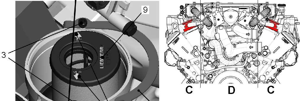
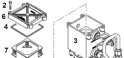
5.6.5Oil separator
Note!
Be sure that :
–The diesel engine is in maintenance position
–Both oil separators and their O-Rings are ready to use.
Disassembly the oil separator filter
Loose the hose clamps 1 and draw the hose 2 off the regulating valve lid 5
Loose the screws 3 and open the bracket 4
A Opened position B Closed position
Remove the lid of the regulating valve
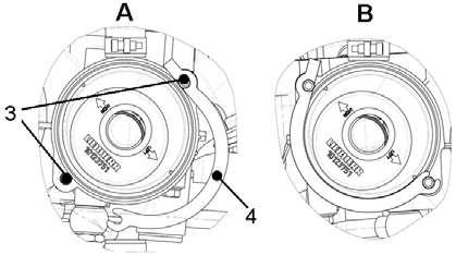
Remove the filter
Assembly
The Oil Separator Filter
Lubricate the O-ring 7 of the new filter with clean fuel or oil.
Insert the new filter.
Caution !
The arrows 8 on the filter have to be into line with the screws 3 !
LIEBHERR logo 9 has to be in the motor inside !
Position the O-ring 10 on the regulation valve lid. Lubricate it with clean fuel or oil. Assemble the lid of the regulation valve, put it in the correct position (mind the current direction).
Put the bracket 4 in closed position and srcew 3 Slip on the hose and retighten the hose clamps.
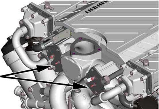
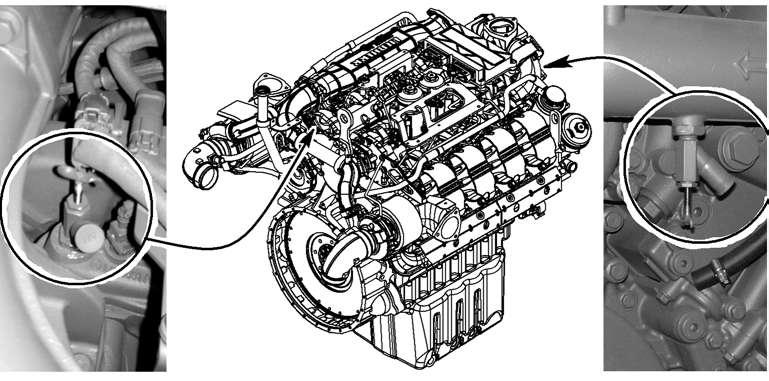
5.6.6Heater flanges
An electrical heater flange is installed at the input of each intake air manifold, at the right side and at the left side of the Diesel engine. The proper function of these heater flanges must be verified every year, at the beginn of the cold season.
Switch off the batteries main switch.
Disconnect the electrical wires at the heater flanges.
Connect an ohmmeter between the both terminals of each flange and measure the resistance.
At a temperature of about 20°C the measured resistance value must be 250±10 mOhms, if this value is not reached, the heater flange must be replaced.
Reconnect the electrical wires to the heater flanges and turn on the batteries main switch.
5.6.7Checking and adjustment of valve clearance Preparation
It must be ensured that the Diesel engine is in the maintenance position and that new seals for all cylinder head covers are on-hand.
Note !
–The cylinder number 1 is always situated at the opposite of the flywheel side and at the right engine side when facing the flywheel.
–The sense of rotation of the engine is counterclockwise when facing the flywheel.
–The exhaust valves are on the flywheel side on cylinders 1 to 4 and on the fan side on cylinders 5 to 8.
Fig. 5-21 Arrangement of cylinders, intake and exhaust valves
A = Exhaust valvesE = Intake valves
Dismount the cylinder head covers.
Attach the manual engine slewing device to the stater gear ring, see also the paragraph "starter ring gear lubrication".
Turn the engine in its sense of rotation until exhaust and intake valves overlap at the cylinder which is corresponding to the cylinder to be adjusted.
Sequence of valve clearance adjustments - 8 cylinders V-engine D9508
Valves overlap at cylinder15726348
Valves clearance adjusted at cylinder63481572
Tab. 5-15 Correpondence between overlapping valves and valves to be adjusted
Checking and adjusting the valve clearance
Insert feeler gauge between valve fitting and rocker arm and check the valve clearance.
Checking and adjusting intake valve clearance
Checking and adjusting exhaust valve clearance
If the clearance does not correlate with the prescribed adjustment values: Loosen the lock nut on the adjusting screw of the respective rocker arm and correct the setting.
Tighten lock nut with 45 Nm. Check adjustment again.
When all the intake and exhaust valves have been checked or adjusted: fit cylinder head covers with new seals. Remove the manual engine slewing device from the stater gear ring.
5.7LIEBHERR particles filter (option)
Water separator
The exhaust back pressure is mesured in the pressure line connecting the control unit A175 to the particles filter housing. A water separator filter is integrated in this pressure line. The periodic maintenance works for the particles filter system are limited to this component.
5.7.1Drain the condensation water
The water separator must be drained regularly. Turn the screw 203 counterclockwise for 90° and collect the condensation water into an adapted container.
Retighten the screw 203 by turning clockwise.
5.7.2Water separator maintenance
Drain the water separator.
Unscew and remove the filter housing 201
Unscrew the nut 105
Notice!
The metallic screen 103 must be checked for good condition every 500 operating hours and cleaned if necessary. It must be changed every 1000 operating hours.
Remove the filter components 101 to 104, and wash or replace the metallic screen 130
Reassemble the filter components 101 to 104 in the right sense and in the right order,reinstall and then retighten the nut 105
Reinstall the filter housing 201 complete with the O-ring 202
For replacement, repair and other maintenance works on the particles filter, see the service manual or consult the LIEBHERR after sales service.
5.8Cooling system
5.8.1Checking and cleaning the cooling system
The machine has a combined turbocharged air and water cooler unit. Optimal cooling can only be achieved when the cooler is kept clean.
Check the fan motor, the fan and the cooler core for damage and clean parts as necessary.
If required, clean the cooling fins with compressed air or a steam jet (from inside out, see arrow).
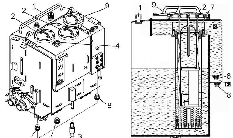
In case of leaks, change the coolant circuit pressure relief valve 7 mounted to the expansion reservoir and/or the filler cap 6.
Regularly check the condition and seals on the connecting clips between the coolant cooler and engine as well as on the coolant hoses regularly.
5.8.2Checking the coolant level
Danger!
Risk of burning due to hot coolant. The engine cooling system is hot and pressurized when at operating temperature. Avoid touching coolant or coolant-bearing parts.
Only check the coolant level when the cap 6 of the filler neck has cooled off sufficiently to touch.
When the engine is very hot, preferably first let the pressure escape by slowly turning the pressure relief valve 7 accessible via the flap 5 in the cooler hood.
Turn the cap 6 a half turn and let any pressure that may be present escape in this position.
After balancing the pressure, slowly turn fully and remove the cap 6 When engine is cold, the coolant level must reach the top of the filler neck under the cap 6
Add coolant if necessary. Close the cap 6
After adding coolant, allow the engine to run for a short time with the cab heating switched on and check the coolant level once again.
5.8.3Changing the coolant
Danger!
Risk of burning due to hot coolant. Only change the coolant when the engine is cold.
The following points should be noted when changing the coolant:
–Change the coolant in the entire coolant circuit at least every two years. –Always change the coolant with the shutoff valves for the cab heating circuit closed.
Note!
If the coolant has been changed without closing the shutoff valves for the cab heating circuit, the heating circuit must be bled, see chapter "maintenance of heating circuit".
To be sure that the coolant flows through the heating system, the ignition key must be in contact position and the cab heater must be set manually to maximum heating power.
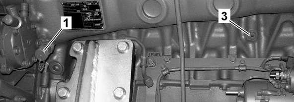
Draining the coolant
Remove the filler cap 6 at the filler neck.
To drain the coolant at the Diesel engine: Unscrew the protection cap of the drain valve 1 on the front side of the engine, screw the supplied drain hose to the drain valve 1 and let the coolant drain into a suitable container.
Unscrew the protection cap of the drain valve 2 on the rear side of the engine, screw the supplied drain hose to the drain valve 2 and let the coolant drain into a suitable container.
Unscrew the protection cap of the drain valve 4 on the rear side of the engine, screw the drain hose to the drain valve 1 and let the coolant drain off.
Remove the drain screw 3 on the front side of the engine housing and let the coolant drain into a suitable container.
Reinstall and retighten the protection caps of the drain valves 1, 2, and 4 and the drain screw 3.
To drain the coolant at the cooler:
Fig. 5-30 Coolant draining valve on watercooler
Unscrew the protection cap of the drain valve 5 at the bottom of the coolant cooler.
Screw the supplied drain hose to the drain valve 5
Let the coolant drain into a suitable container.
Reinstall and retighten the protection cap of the drain valve 5.
Refilling the coolant and bleeding the coolant circuit
Add coolant via the cap 6 up to the upper edge of the filler neck of expansion reservoir.
Close the cap 6 again.
Open the shut-off valves for cab heating circuit and adjust the heating system to maximum heating power.
Start the engine and let it run at low idle for approx. one minute.
Open the cap 6 and add coolant up to the upper edge of the filler neck of expansion reservoir. Add coolant until the level does no longer drop. It is not possible to overfill the coolant system when the pressure relief valve 7 is installed!
Close the cap 6 again.
If the coolant level sensor actuates during machine operation, check the coolant level and, if necessary, top up with coolant as described above.
Caution!
The engine could be damaged.
If the indicator light for coolant overheat or the symbol for low coolant level lights up, bring the engine to low idle immediately.
Switch off the engine after a few seconds.
Check the coolant level and refill with coolant if necessary.
5.8.4Check of the coolant and adjustment of the mixing ratio
Coolant with corrosion inhibitor/antifreeze agent
The mixing ratio must at all times conform to a frost protection of -37°C. Take a coolant sample and analyse it with a suitable method for the frost protection temperature. If the frost protection is not sufficient, adjust the mixing ratio.
1 Corrosion inhibitor/antifreeze agent (concentrate), refill volume in litres
2 Auxiliary line
3 Max. frost protection temperature of the cooling system -°C
4 Coolant volume in radiator in litres
Determination of the refill volume - example for -15°C / 50 litres of coolant
Based on the measured frost protection temperature (-15°C) follow the auxiliary line 2 from the left bottom corner to the vertical line 4 (coolant volume – 50 litres) and from there horizontally to the left scale. The refill volume 1 is 14.8 litres. This corresponds to the refill volume of corrosion inhibitor/antifreeze agent (concentrate) to be added in order to again achieve a frost protection temperature of -37°C.
Correction of the mixing ratio
Make sure that the necessary refill volume is known.
To correct the mixing ratio, at least the previously determined volume must be drained from the cooling system.
Add the determined volume of corrosion inhibitor/antifreeze agent (concentrate).
To achieve the required coolant level, add some of the previously drained coolant.
Coolant with corrosion inhibitor (without antifreeze agent)
When using DCA 4
Take a coolant sample and analyse the concentration using a Fleetguard CC 2602 M testing kit.
If the concentration is incorrect, correct the mixing ratio (according to the values indicated by the test kit).
When using Caltex / Chevron / Havoline / Total
The mixing ratio must always show a Brix value of 2.8-0.9+0.9 %. This corresponds to 5 to 10% of corrosion inhibitor and 90 to 95% of water.
Take a coolant sample and analyse with a Gefo refractometer.
Refractometer
–Adjusting screw for adjustment to 0-line (water line)
–Adjustment of acuity by turning the eyepiece
–Soft edge of eyepiece
–Sturdy metal housing
–Safe handling thanks to rubber jacket
Measuring procedure
Carefully clean the lid and prism.
Apply 1 to 2 drops of sample liquid onto the prism. Close the lid. The liquid is distributed.
Hold the device against a light-coloured background and look through the eyepiece.
Adjust focus on scale and read the value at the blue separating line.
1 Corrosion inhibitor, refill volume in litres
2 Auxiliary line
3 Refractometer value in %Brix
4 Coolant volume in radiator in litres
Determining refill volume - example for 1% Brix / 50 litres of coolant
Based on the measured value (1%Brix), follow the auxiliary line 2 from the left bottom corner to the vertical line 4 (coolant volume – 50 litres) and from there horizontally to the left scale. The refill volume 1 is 2.4 litres.
This corresponds to the refill volume of corrosion inhibitor (concentrate) to be added in order to again achieve a value of 2.8% Brix.
Correcting mixing ratio
Make sure that the necessary refill volume is known.
To correct the mixing ratio, at least the previously determined volume must be drained from the cooling system.
Add the determined volume of corrosion inhibitor.
To achieve the required coolant level, add some of the previously drained coolant.
5.8.5Reversible fan (option)
General
The option "reversible fan" allows an easy cleaning of the cooler cores by inverting the way of rotation of the fan.
Cleaning the cooler
Danger !
Before checking the condition of the cooler, you must absolute shut off the engine and wait until the fan does not turn any more.
With running engine, depress the push button S160 and keep it depressed. The fan stops progressively (approx. 15 seconds), then the control light H90 lights up and the fan starts rotating in the opposite way.
In case of a diesel engine, bring it to high idle while keeping the push button S160 depressed.
Let the engine run at high idle for approx. 1 minute (max. 3 minutes).
Release the push button S160
The control light H90 goes out, the fan stops progressively (approx. 15 seconds), then the fan rotates in the normal way again.
Shut off the engine.
Wait until the fan does not turn any more.
Check the condition of the cooler. If necessary, repeat the cleaning procedure.
5.9Fuel system
DANGER!
Extremely flammable liquids! Explosion hazard.
Keep sources of ignition or sparks away from the fuel system. Do not smoke.
Only work on the fuel system when the diesel engine is shut down.
5.9.1Refuelling Fuel filler cap
Caution!
Humidity admission into fuel filler cap! Damage.
Remove key from fuel filler cap. Put in protective cover of fuel filler cap.
Unscrew fuel filler cap 15. Add fuel via the filler sieve 20
5.9.2Electrical refuelling pump (optional extra)
1 Intake hose S25 Button ON
2 Shut off valve S59 Button OFF
3 Operating unit
The electrical refuelling pump is used to put fuel into the machine’s fuel tank. It is located under the hatch on the front end of the hydraulic oil and fuel tank. The operating unit 3 is removable.
Refuelling pump data
Refuelling pump start up
Unscrew the fuel filler cap 15
Insert the free end of the intake hose 1 in the fuel supply tank down to the bottom of the tank.
Open the shut off valve 2 (position B).
Use switch S25 (green) to switch on the refuelling pump in order to pump fuel into the machine’s tank.
The pump switches off automatically as soon as the maximum fill level is reached.
The refuelling pump can be switched off at any time using switch S59 (red).
Caution !
Refuel only with clean diesel.
Ensure that the filter (at the end of the intake hose) is not damaged or plugged in order to protect the pump against foreign bodies.
The pump must not be permitted to run dry.
Ensure that the fuel level does not drop below the intake level of the intake hose.
Ensure that the valve 2 is open before the pump is working. Make sure refuelling is going smoothly.
Refuelling pump switch off and stowing the hoses
The pump is stopped.
Close stop cock 2 (position A).
Ensure that no fuel remains in the intake hose 1 before stowing. Roll up the intake hose 1 and place it in the stowing compartment.
Close the hatch again.
Screw the fuel filler cap 15.
Caution !
After a refuelling, the pump body has to stay full of gasoil to avoid the jamming of it.
Only close the stop cock when the pump is stopped. Do not change intake hose’s length or/and diameter.
Note !
To avoid watercondensation in the tank, refuel at the end of the workingshift.
Filling a tank fitted with quick refuelling coupling (option)
The fuel tank can be equiped with a quick refuelling coupling if the employed tank truck is fitted with the corresponding coupling system too. Depending on the execution of the machine and on customer’s wish, this coupling can be installed under the cover front right (2a), at the front (2b) or in the side wall (2c) of the fuel tank.
Caution!
The fuel filler cap 1 must remain installed on the tank during refuelling via the quich refuelling coupling. Otherwise no automatic cut off of the fuel gun will happen and the tank will overflow.
To safety access the refuelling coupling 2: place a work platform or a work ladder, minimum height 60 cm, close to the machine.
Remove the cap of the filler coupling 2
Connect the fuel gun to the coupling 2
Add fuel.
Once the tank is full, the vent valve 3 closes. Causing the counterpressure in the tank to increase and the fuel gun to stop refuelling automatically.
Remove the grease gun from the coupling 2
Reattach the cap to the filler coupling 2
5.9.3Draining the fuel tank
15 Filler cap 20 Filler sieve 36 Drain valve
To daily drain the fuel tank and the fuel system: Place a suitable container underneath.
Unscrew the drain valve 36 mounted to the bottom sheet of the fuel tank. Drain off the water until water free fuel escapes. Close the drain valve 36 again.
If the operating conditions and the fuel quality allows, the water draining interval can be increased to once a week.
Note!
To reduce the formation of condensate in the tank, keep the fuel level as high as possible. Preferably refuel the tank at the end of the working day.
Display P3 indicates the fuel level.
When the red bar P3.1 illuminates, a low reserve quantity is still in the tank. In the event of a low fuel level, refill the tank before starting to work..
5.9.4Emptying and cleaning the fuel tank
The bottom of the tank is fitted with a drain valve 36 Place a suitable container underneath.
To drain off the water, unscrew the drain plug on the drain valve 36 by two turns and let the water flow out until water free fuel escapes.
Retighten the plug of the drain valve 36
To empty the fuel tank totally, remove both the fuel filler cap 15 and the drain valve 36 and collect the fuel in a suitable container.
Check the fuel tank and filler sieve 20 regularly for contamination.
If necessary, replace the filler sieve 20 and / or wash out the fuel tank.
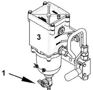
5.9.5Draining the fuel prefilter
Fig. 5-39 Drain valve at fuel prefilter
The water separator of the fuel pre-filter must be drained on a daily basis and, if necessary, each time the symbol E528 appears at the display of the machine: Position a collecting container underneath. Press the drain valve 1 of the fuel prefilter 3 and then turn it clockwise to open. Let the water flow out until water free fuel escapes. Close the drain valve 1 again.
5.9.6Replacing the fuel filter elements
Danger !
There is a risk of fire and explosion! No smoking !
Avoid open flame ! Perform maintenance works only after the Diesel engine is shut down.
Replacing the fuel prefilter element
1 Water drain valve
3 Filter housing
5 Paper filter element
7 Spring holder plate
2 Screw
4 Seal
6 Filter cover
Position a collecting container under the fuel pre-filter 3
Clean fuel pre-filter and the surrounding area thoroughly.
Press the handle of the water drain valve 1 and turn it clockwise, let the fuel flow out of the filter housing.
Loosen the screws 2 and take off the cover 6 with the seal 4
Take off the paper filter element 5 complete with the spring holder plate 7.
Dispose of the old paper filter element 5.
Install a new filter element 5
Check the good condition of the seal 4 and replace seal as necessary. Reassemble the complete fuel prefilter.
Bleed the fuel prefilter after replacement of its filter element.
Replacing the fuel fine filter elements
The fuel fine filters are situated under the protection running plate, in the V-area at the top of the engine.
Remove the running plate.
Clean fuel fine filters and the surrounding area thoroughly.
Position a collecting container under the fuel draining pipe. Unscrew the fitting 1 at the fuel draining pipe.
Using a suitable tool loosen the both covers of the fine fuel filters. Unscrew the covers 1 until the breather holes under the o - rings 2 are free.
Wait until all the fuel in the filter housing has drained off into the collecting container.
Remove the both covers 1 complete with the fine filter elements 3
Pull the fuel fine filter elements 3 away from the covers 1
Dispose of the old filter elements 3
Replace the O - rings 2 and clean the covers 1 as necessary.
Caution!
Introduction of dirt can cause the destruction of the Common Rail system! It is essential that no contaminants attain the clean side of the filters.
Leave the remaining fuel inside the filter housing. Do not attempt to sponge up the filter housing using a rag.
Never reuse an allready used fuel filter element..
Use only new original Liebherr fuel fine filter elements 3 .
Reinstall the fuel fine filter elements 3 complete with the covers 1 and tighten to prescribed torque (20+5 Nm or 15+4 ft.lbs ).
Retighten the fitting 1 to close the fuel draining pipe.
Refill the fuel system using the hand pump. Reinstall the protection running plate.
5.9.7Bleeding the fuel system
A complete bleeding operation consists in bleeding first the fuel prefilter and then the low pressure fuel system.
The bleeding of the fuel system becomes necessary after replacement of the fuel filter elements, after running the fuel tank empty and at initial start up of the Diesel engine.
Note !
Impurities in the fuel system cause the the Common Rail system to disfunction. Injection lines must not be opened or loosened. All works at the components of the Common Rail Systems are only to be performed by specially trained personnel.
The Diesel engine must be shut down for at least one Minute to allow the pressure in the rail to decrease before working in the high pressure system. For all works and any parts of the fuel system, it is essential to respect absolute cleanliness (e.g. washing hands, wearing clean work dress). Humidity is to be avoided absolutely.
Bleeding the fuel prefilter:
Bleeding the fuel prefilter
Unscrew the bleeder screw 1 at the filter head of the fuel prefilter by 2 or 3 turns. Actuate the hand pump 2
Retighten the bleeder screw 1 as soon as bubble-free fuel escapes from bleeder screw.
Continue actuating the hand pump 2 until you notice a more intense resistance.
Bleeding the low pressure fuel system:
Loosen the fitting at the fuel return line (see arrow).
Continue actuating the hand pump 2
As soon as bubble-free fuel escapes, retighten the fitting at the fuel return line. Continue actuating the hand pump 2 until you notice a more intense resistance. Start the engine.
Note !
If the engine does not start after a 20 seconds cranking: respect a pause time of 1 minute, perform a new starting attempt (maximum duration of 20 seconds).
If the engine does not start after three starting attempts, repeat the bleeding procedure.
5.10Dry air filter
Maximum engine protection against early wear due to dust is only possible if the air filter is serviced at regular intervals.
The dry air filter is designed in such a way that it offers maximum protection and long maintenance intervals.
The maintenance mainly consists in changing the filter elements 3 and 4. For safety reasons it is not recommended that filter elements be washed out.
2
9
10
20
The maintenance indicators 9 store the maximum recorded intake air depression occurring at the filter outlets, during the Diesel engine operation.
The appearance of the red indication strip 12 in alarm window 10 indicates that the maximum permissible vacuum of 5 kPa (50 mbar) has been reached.
At that time, replace the primary filter element 3
Press the reset button 11 of the vacuum gauge 9 to clear the stored low pressure reading.
5.10.1Changing the main element
Caution!
Only replace the main element 3 when the maximum permissible intake depression has been reached, or at least once a year.
Installing and removing the main element 3 too often could damage the seals between the filter element and the filter housing 2
7
8
9
Swivell up the cover 1 with the engine switched off.
Remove the retaining rod 6 and the wing nuts 8
Remove the contaminated main elements 3
Clean the interior of the air filter housing 2 using a damp cloth.
Insert the new main elements 3 and ensure that they are sealed and positioned correctly.
Reinstall the wing nuts 8 and the retaining rod 6.
Close the cover 1 of the filter, taking care that the seal 19 is positioned correctly
5.10.2Changing the safety element
Note!
Replace the safety elements 4 after replacing the main filter cartridges 3 three times or at least once a year.
In addition if, when changing the main elements 3, you notice that the green dots 7a on the special nuts 7 have turned red, you must replace the safety elements 4 immediately.
Remove the main elements 3 as described above
Remove the special indicator nuts 7 and the safety elements 4
Clean the interior of the air filter housing 2 carefully using a damp cloth. Clean the sealing surfaces in the housing 2 and inspect for any damage.
Caution!
Dirt could enter the engine air intake manifold! Do not clean the housing by blasting out with compressed air.
Insert the new safety elements 4 carefully and secure using the special nuts 7. Insert the main filter cartridges 3 as described above
Close the filter housing 2 with cover 1
5.10.3Checking the intake air lines
At each replacement of filter elements, check the filtered air line between the filter outlet, the turbocharger, the charged air aftercooler and the engine intake pipe (as an ex. the air hose 20) for damage and leaks.
If necessary, retighten the screws of the tensioning clamps 21 and 22
5.11Hydraulic system
Maintenance work on the hydraulic system is restricted mainly to the hydraulic tank. All other units on the system do not require any special maintenance. However, the pipe and hose network must be checked at regular intervals for leaks.
Note!
Strict cleanliness is of particular importance for the hydraulic system. For this reason, the intervals given –for changing the return-line filters –for cleaning the oil cooler and –for changing the oil must be adhered to.
5.11.1Depressurizing the hydraulic system
Before any intervention on any hydraulic component, you have to depressurize the hydraulic system.
Danger!
Do not inspect leaks with bare hands. A fine stream of liquid can penetrate the skin when under high pressure and cause serious injury.
Note the following points:
The machine must stand level and the attachment must be laid down on even ground.
To relieve pressure in the high pressure circuits
Switch off the engine.
Briefly move the pilot control devices (joystick and pedals) in all directions (with the ignition key in the contact position).
To relieve pressure the servo oil circuits
Move the pilot control devices (joystick and pedals) several times in all directions (with the ignition key in the contact position).
To depressurize the hydraulic tank
Unscrew the vent filter 1 by a maximum of one turn. The hydraulic tank will depressurize.
The vent filter 1 can be turned manually if safety stud 2 is inserted. An open-ended spanner can be used if the filter does not open easily
Note!
The retaining pin 2 (or anti vandalism key) must be systematically removed from the vent filter 1 and hung with the ignition key.
Danger!
The hydraulic oil is hot when at operating temperature and could be pressurized. Do not allow the hot oil or oil-bearing parts to touch the skin.
5.11.2Checking the oil level, emptying and refilling the hydraulic tank
Machine position
Fig. 5-49 Machine position for checking the oil level in the hydraulic tank
When checking the oil level or refilling the oil: –the machine must stand on level floor, –the attachment must be laid down on even ground with the stick and bucket cylinders fully extended (bucket and stick fully tilted in), –the Diesel engine must be switched off. –if applying the bottom dump bucket must be closed.
Checking the oil level in the hydraulic tank
Level
When the machine is in the check position, the level must not be below the middle marking on the sight gauge.
If this is not the case, fill oil through the return filter until the oil level reaches the middle marking.
The upper marking MAXI shows the maximum oil level when all cylinders are fully retracted.
The lower marking MINI shows the minimum oil level when all cylinders are fully extended.
If the oil level drops below the lower marking MINI, the symbol appears on screen when the lowest quantity is reached.
Emptying and refilling the hydraulic tank
1 Breather filter
4
8
9 Return filter (Main oil flow)
If possible, always fill and empty the hydraulic system using a filler unit.
To drain the oil:
The hydraulic system must be depressurized.
Unscrew the breather filter 1 by a maximum of one turn. The hydraulic tank will depressurize.
Remove the cover 2 of a return filter 9
Screw the drain hose to the drain valve 5 at the bottom of the hydraulic tank. Let the oil flow out into a suitable container.
Screw the drain hose to the drain valves 6 and then 8 and let the oil flow out of the collecting compartments R and Rl into the collecting container.
To refill the hydraulic oil:
Unscrew the breather filter 1 by a maximum of one turn. The hydraulic system will depressurize.
Remove the cover 2 of one of the return filters 9.
Refill the oil through the removed filter cover 2 (or through the flange 4 on collecting compartment) until the level reaches precisely the central marking on the sight gauge.
Retighten the breather filter 1
Refill the tank up to the top. If refilling through the filter cover 2, be sure to refill also completely the collecting compartment around the filter centering tube 7. Screw on the cover 2 of return-line filter or the flange 4.
Caution!
After each hydraulic oil change, vent the hydraulic pumps.
To drain off condensation water
Drain off the condensation at the regular intervals specified in the maintenance chart. Place a suitable container underneath.
Keep the drain hose on the drain valve 5 until water free oil flows out.
Note!
When using "environmentally friendly hydraulics fluids" and after machine down time (after about 24 hours), we recommend to drain off the condensation in the hydraulic tank before operating the machine.
5.11.3Checking and cleaning the oil cooler system
11 Hydraulic oil cooler
13 Charging air cooler
15 Pumps splitterbox oil cooler
12 Water cooler
14 Fuel cooler
16 Condensor of airco plant
The oil cooler is integrated in the coolers arrangement consisting of two combined cooler units. Keeping the oil cooler in clean condition is prerequisite for an optimum hydraulic oil cooling.
Check cooler and fan for damage and clean if necessary. Regularly clean the cooling fins with pressure air or steam jet from the insite out.
5.11.4Return filter
The three return filters are located on the top of the hydraulic tank. The both return filters 9 filtern are for the main oil return flow of the hydraulic circuit. The leakage oil flows of the hydraulik pumps and motors are gathered in a separate return circuit streaming to the tank via the leakage oil return filter 10.
1 Breather filter
2 Return filter cover
3 Sealing
4 Magnetic rod
5 Filter element
6 Screw
9 Return filter for main oil flow
10 Return filter for leakage oil
The magnetic rods 4 of all the three return filters 9 and 10 must be cleaned and the glass fibre filter elements 5 replaced at fixed intervals (see maintenance chart) .
Note
When working in heavy dust conditions, please note the special regulations for changing the filter.
To clean a magnetic rod and replace a filter element: The hydraulic system must be depressurized.
Unscrew screws 6 on the filter cover and lift out cover 2 with magnetic rod 4.
Carefully clean off any dirt sticking to the magnetic rod 4
Remove the used filter cartridge 5 while lifting it at the clamp.
Insert the new filter cartridge using the clamp vertically into the tank and press down lightly. Then lay the clamp to the side on the tank ring.
Caution!
Ensure that the filter cartridge is standing vertical in the tank and that the sealing faces on the filter element are not damaged.
Position and center the cover unit 2 complete onto the filter element 5. When doing this, ensure that the sealing 3 is positioned correctly and is in good condition.
Retighten the screws 6
Retighten the breather filter 1
5.11.5Servofilter
The servo oil filter 11 is part of the control oil unit 1 which is located on the rear of the hydraulic tank.
1
2
10
11
Note!
12
13
14
15
It is not permitted to clean the filter element 12.
Change the filter element each time you open the filter housing 14
To replace the filter element:
The hydraulic system must be depressurized.
Unscrew the filter housing 14 of the servo filter 11 and remove filter element 12
Clean the filter housing 14
Oil the threads and sealing surfaces on filter housing 14 and on control oil unit 1 as well as sealing rings 13 and 15 with hydraulic oil.
Push the new filter element 12 carefully onto the centering pivot 2
Screw filter housing 14 by hand to the stop and turn it back from a 1/4 turn (approx. 90°).
5.11.6Replenishing oil filter in swing circuit
The replenishing oil filter is mounted on the swing pump.
2 Filter housing
3 Filter element
7 Coil
10 O-ring
Unscrew filter housing 2 and remove filter element 3 and O-ring 10
Clean the filter housing 2
Oil the thread and sealing surfaces of filter housing 2 and of filter head on swing pump.
Carefully install the coil 7 and the new filter element 3 with the a new O-ring 10. Screw the filter housing 2
5.11.7Servo control circuit
The control circuit does not require any special maintenance.
Regularly inspect for leaks the pipe network and connections on all components (pressure accumulator, pressure limiting valve, pressure filter etc.) .
Danger!
The pressure accumulator 10 maintains the servo control circuit under pressure for a small number of actuations even after the Diesel engine shutdown. Before working on the control circuit, relieve the servo pressure as follows: Lay the working attachment down to the ground. Switch the engine off.
Actuate both joysticks several times (with the ignition key in contact position and the safety lever tilted down).
5.11.8Air bleeding of the servo control chambers
With the time the air contained in the hydraulic fluid of the machine can collect in the servo control chambers of the control valves and form there air cushions.
This condition is generally noticed by the excavator driver when, during actuation, one or several movements are reacting jerkily, lazy or time delayed.
Bleed in this case, and in any case at the regular intervals indicated in the maintenance chart, the servo control chambers, using the push button S248 and according to the following procedure:
Notice!
The electronics of the machine allow the starting of a bleeding procedure only if: •the hydraulic oil temperature is at least 20°C (70°F).
•the working attachment of the machine is lowered down to the ground and no pressure remains in the high pressure circuit of the boom cylinders.
Relieve the pressure in the circuit of the boom cylinders. Therefore, lower the attachment down to the ground, turn off the Diesel engine, and then actuate both joysticks in all directions with the ignition key in contact position.
Start the Diesel engine and bring it to high idle RPM, tilt the safety lever down: at the display, the symbol indicating unsufficient servo oil pressure (symbol "PST") must go out.
(The servo pressure must be correct to ensure the effectiveness of the air bleeding procedure).
Fig. 5-56 Air bleeding of servo control chambers
Depress the push button S248 at the rear control desk and keep it depressed for approx. 70 seconds.
the symbol air bleeding - "ON" appears on the monitoring display. the servo control chambers of all of the main control valves installed on the machine are air bled progressively and one after the other.
Release the push button S248 after approx. 70 seconds. the symbol Air bleeding - "OFF" appears temporarily on the display. the air bleeding procedure is over.
5.11.9Bleeding the hydraulic pumps
After maintenance works on the pumps or after oil change in the hydraulic system, the hydraulic pumps must be bled.
Note!
To bleed the pumps, it is advised to use the special kit (order nb. 7408148) to get the hydraulic tank under pressure.
If the pumps are bled without eploying the special kit or pressurizing the tank, the engine must be run at low idle (800-900 RPM) for the whole duration of the bleeding procedure.
1 Fitting / bleeding of working pump
3 Working pump
5 Plug / bleeding of cooler fans driving pump
2 Plug / bleeding of swing pump
4 Swing pump
6 Cooler fans driving pump
To bleed a working pump 3, loosen the fitting 1 and let the air escape. As soon as oil free of air bubbles flows out, retighten the fitting 1
To bleed the swing pump 4, loosen the plug 2 and let the air escape. As soon as oil free of air bubbles flows out, retighten the plug 2
To bleed the cooler fans driving pump 6, loosen the plug 5 and let the air escape. As soon as oil free of air bubbles flows out, retighten the plug 5.
The pump housings must be filled up with hydraulic oil via the above mentioned orifices before intial starting of the pump as well after repairing or replacing a pump.
5.11.10Bleeding the hydraulic cylinders
A cylinder must be bled after cylinder replacement or after maintenance works on the cylinder (replacement of seals,...) or on its hydraulic circuit (replacement of a hose, ...).
Hydraulic cylinders fitted with bleeder plugs 2 must be bled according to the procedure 1 below and hydraulic cylinders without these bleeder plugs according to the procedure 2.
Procedure 1
Unscrew the bleeder plugs 2 on both sides of the cylinder.
Screw in gauge couplings 3 into bleeder holes and fit each coupling with a test hose.
Start the engine and keep it running at low idle (800-900 RPM).
If possible, move the attachment in such a way the cylinder side to be bled is in the higher position.
Carefully actuate the cylinder. It is recommended to bleed first the side, which does not necessitate a displacement of the cylinder (for example, if the cylinder is already retracted, first actuate the cylinder retraction in order to bleed the cylinder rod side).
Continue until oil free of air bubbles flows out of the test hose.
Supply the other side of the cylinder and bleed it.
Switch off the engine, remove the test hoses and replace the gauge couplings 3 by the bleeder plugs 2
Perform the procedure 2.
Procedure 2
Start the engine and keep it running at low idle (800-900 RPM).
Slowly and regularly extend the cylinder until stop, then slowly and regularly retract it all the way to the stop. Repeat the operation 5 times. .
The incorrect bleeding can cause the appearance of gas bubbles (mixture of air and hydrocarbon) which could explode due to the high pressure in the cylinder (Diesel effect).
5.11.11Removing the suction hose to the pumps
For maintenance reasons (change of a suction hose, removal of a pump), the suction hoses to the pumps can be isolated from the hydraulic tank thanks to shut off valves.
1 Drain plug
3 Suction hose
2 Shut off valve
4 Pump suction neck
The shut off valve on the hydraulic tank to the suction hose has two positions : – a open – b closed
Depressurize the hydraulic system. Close the shut off valve on the hydraulic tank b
Unscrew the drain plug 1 in the pump suction neck. Drain the hydraulic oil out of the pump and suction hose. Once the repair work is completed, turn the shut off valve back to its initial position a and engage.
Retighten the vent filter on the hydraulic tank.
5.11.12Breather filter on the hydraulic tank
The hydraulic system must be depressurized. Replace the breather filter 1 and the retaining pin 2 at the regular intervalls indicated in the maintenance chart.
Note!
When working in heavy dust conditions, please note the special regulations for changing the breather filter.
The retaining pin 2 (or anti vandalism key) must be systematically removed from the breather filter 1 and hung with the ignition key.
5.11.13Bypass oil filter for hydraulic system (option)
The purpose of the bypass oil filter is to eliminate the smallest impurities and the water contained in the hydraulic system.
The bypass oil filter is mounted to the front of the hydraulic tank, resp. in the hydraulic pumps compartment.
On machine model R964 C and above, two bypass oil filters are mounted in parallel due to the oil flow to be filtered.
Note!
LIEBHERR insistently recommends to fit with a bypass oil filter the excavators which are operated with environmentally friendly hydraulic fluids.
Bypass oil filter for hydraulic system
1 Pressure gauge
3 Filter housing
2 Tightening clamp
4 Filter element
The more the oil is contaminated, the higher the pressure in the filter housing. Depending on the machine applications and the dirt/water collection in the filter, the filter cartridge might need to be replaced before the standard change interval (2000 operating hours) is reached.
If the pressure gauge 1 indicates a value of more than 2.5 bar during operation, the filter element is too much contaminated to ensure sufficient filtering of the hydraulic oil.
Checking filter contamination
The contamination grade of the bypass oil filter must be checked at the regular intervall indicated in the maintenance chart
When checking, the hydraulic oil must be at a temperature of at least 50 °C (operating temperature) and the engine must be running.
Read the indication of the pressure gauge.
If the pressure exceeds 2.5 bar, change or get changed the filter element at once.
Replacing filter element
Switch off the engine.
Release the pressure in the hydraulic tank.
Open and remove the tightening clamp 2
Remove the old filter element 4 and collect the oil leaking from the filter in a suitable container.
Check the inlet and outlet sections of the bypass oil filter and if necessary clean the inner side of the filter head.
Insert a new filter element 4
Replace the filter housing 3, replace and tighten the clamp 2
Start the machine and check the bypass oil filter for leakage.
5.11.14High pressure filters in working circuit
These filters are mounted between the working pumps and the inlets of the control valve blocks.
The filter elements must be checked and if necessary cleaned : –regularly every 2000 operating hours, –after each repair or replacement of a working pump.
To clean a filter element : relieve the tank pressure, remove the filter housing 1, remove the O-ring 4, remove the filter element 2, clean it in gasoline or replace it, clean the filter housing 1 and the filter head 3, reinstall all parts (Replace the O-ring 4 by a new one and make sure the O-ring 4, the supporting ring 5 and the spring 6 are seated correctly), retighten the breather filter on the hydraulic tank.
Note!
Anytime after cleaning or replacing the filter element, check the high pressure filter for leaks.
Start the engine, work with the machine for a short period and then check for leaks between the filter housing 1 and the filter head 3.
5.11.15Servicing the hydraulic cylinder Checking the condition of the piston rod mount
Note
When a leak appears on the piston rod mount of a hydraulic cylinder (see arrow), the sealing kit must be replaced by a LIEBHERR fitter.
Protecting the piston rods
When the machine is out of service for more than 4 weeks and particularly for transportation by sea, the following measures must be taken:
Position or transport the machine in such a way that the piston rods are fully drawn into the cylinders.
Cover any loose piston rods with a thick layer of non-corrosive anti-corrosion fluid. Grease quality: see “Lubricating and operating materials”
For sea transportation, check the condition of the piston rods once more after loading.
Additionally, cover piston rods with anti-corrosion fluid if a cylinder only has a low stroke for certain work, meaning that the piston rod is not regularly moistened with hydraulic oil (eg. cylinder on slewing arm when working over ground).
Check the condition of hydraulic cylinders which are not moved a great deal regularly.
5.11.16Replacing hydraulic hoses
Danger!
A defective hydraulic hose can cause accidents and injuries. Replace defective hydraulic hoses (bubbles, moisture, damaged top edge etc.) immediately.
Install new hoses in such a way that torsion loading is avoided. Ensure that the hydraulic hose is not twisted when mounting.
Installed high pressure hoses with SAE connections have a nominal diameter of 16, 20, 25, 32 or 40 (5/8", 3/4", 1", 1"1/4, or 1"1/2).
You must tighten the mounting screws of the SAE fittings with the following tightening torques.:
Size of screw 4Torque value in Nm - Quality 10.9
Half flanges 5aFlat flange 5bConical flange 5c M831// M10624565 M1210870110
M14172120180
M16264170250
M20350250450
Tab. 5-16 Tightening torques for SAE fittings - Quality 10.9
Size of screw 4Torque value in Nm - Quality 8.8
Half flanges 5a
M822
Tab. 5-17 Tightening torques for SAE fittings - Quality 8.8
Size of screw 4Torque value in Nm - Quality 8.8
Half flanges 5a
M1044
M1276
M14122
M16187
Tab. 5-17 Tightening torques for SAE fittings - Quality 8.8
5.12Oil changes on components
5.12.1General information
The machine must be standing level. Switch off the engine.
Wait briefly until the oil has collected in the oil sump. Drain off the oil (preferably when oil is at operating temperature) Add the oil.
Check the oil level.
Oil quality and quantity: see lubricant chart. Change intervals: see lubrication and maintenance chart.
5.12.2Swing gear - Oil level check and oil change
Fig. 5-66 Checking oil level and changing oil in swing gear
1 Oil reservoir
2 Cover
To check the oil level:
3 Drain valve
4 Drain hose
When the gear oil is cold, the level in the expansion reservoir 1 should not be below the marking Min.
Otherwise add oil until the level reaches the marking Max.
To drain the oil:
Remove the cover 2
Unscrew the cover of the drain valve 3 via the opening on the upperdeck.
Screw the drain hose provided 4 to the drain valve 3 and let the oil flow out into a suitable container.
Remove the hose 4.
Screw the cover of the drain valve 3 back on.
To add the oil:
Add the oil in the reservoir until the level reaches the Max. marking.
Screw the cover 2 back on.
5.12.3Travel gear oil change
Perform the oil change at the intervals indicated in the maintenance chart.
Before draining or adding oil, actuate the travel drive until the plug 2 for oil draining is situated straight below the central axle of the gear. Preferably drain the oil when it is at operating temperature.
To drain the oil
Ensure that you have a suitable oil drainage container to hand. Place the container beneath the travel gear.
Remove one oil level plug 1
Remove the oil drain plug 2 The oil drains into the container.
To add the oil
Screw in the oil drain plug 2.
Fill in oil until the level reaches the bore hole 1
Screw in the oil level plug 1
Note!
The track components of the machines working with their undercarriage the most of time underwater, are exposed to increased rust and premature wear. On these machines the oil in the travel gears must be changed every 100 working hours and an oil analysis (water content of the oil) must be performed weekly.
5.12.4Splitterbox - Oil change
4 Cover
6 Drain hose
To check the oil level:
5 Dipstick
7 Drain valve
Check the oil level at the dipstick 5, a few minutes after turning off the engine, to allow the oil to collect in the sump of the splitterbox.
To drain the oil:
Remove the cover 4
Screw the drain hose provided 6 to the drain valve 7 and let the oil flow out into a suitable container.
Remove the hose 6
Screw the cover of the drain valve 7 back on.
To add the oil:
Add the oil via the filler tube under the cover 4 until the level reaches the marking "Max" on the dipstick 5
Screw the cover 4 back on.
Run the engine for a few minutes, stop it and recheck the oil level after a short time.
5.13The track components
The maintenance works necessitated by the tracks assemblies mainly consist of the replacement of the worn components once they have reached their wear limits.
The sealing of the carrier rollers, track rollers and idlers via slipring seals provides an increased durability to the track assemblies while making these parts widely insensitive to any intrusion of dirt or water.
5.13.1Checking the mounting screws of the track components
Regularly carry out a visual inspection for loose mounting screws on the track pads and travel drives.
Regularly check the tightening torques of some screws (take a random sample of about ten screws regularly distributed on the upper side of each chain) and retighten all the screws if you notice that at least one screw has loosened.
–The track pads mounting screws 7 must be torqued to:
ComponentMounting bolt Test torquePre-tightening torque and turning angle
–The mounting screws 8 of the travel gears to the side trames must be torqued to:
•(Screws - M24 - 12.9) : 1120Nm (830 ft.lbs)
•(Screws - M30 - 10.9) : 1900Nm (1400 ft.lbs)
–The mounting screws 9 of the sprocket wheels must be torqued to:
•(Screws - M24 - 12.9) : 1120Nm (830 ft.lbs)
•(Screws - M30 - 10.9) : 1900Nm (1400 ft.lbs)
–The mounting screws 10 of hydraulic motors to travel gears must be torqued to:
•(Screws - M24 - 10.9) : 960Nm (710 ft.lbs)
5.13.2Checking the track chains tension
Due to normal wear of the tracks, the chain tension needs to be checked regularly, and, if necessary, the chains must be tightened.
Relieve the track by driving the machine forwards and backwards. Place the measuring rod 1 in the area above the carrier rollers. Measure distance A between the measuring rod lower edge and the top of the track pads.
On machines with two carrier rollers per side, the track should, under operating conditions, sag 20 to 30mm between the carrier rollers.
On machines with three carrier rollers per side, the track should, under operating conditions, sag 15 to 20mm between two consecutive carrier rollers..
Note!
As an alternative, or if no correct measuring rod is available, it is possible to determine the sag A as the difference between X1 and X2 (A = X1 - X2).
X1 is the distance between lower face of a chain link and the cover sheet of the side frame measured at a carrier roller, X2 the same distance measured in the middle between two carrier rollers.
5.13.3Retensioning the track
Fig. 5-72 Retensioning the track
Remove the cover 6 on the side frame of the undercarriage.
Screw high pressure hose 2 onto the manual grease gun 1
Through the opening in then side frame, connect the high pressure hose 2 to the lubricating nipple 3 of the grease tensioner 4
Inject grease until the track is sufficiently tensioned.
Check the track tension as described above.
Remove the grease gun 1, the pressure hose 2 and reattach the cover 6
5.13.4Releasing the track chain tension
Danger!
Risk of injury due to sudden dropping of the crawler or to a jet of grease under high pressure.
Because of the risk of grease jet, always wear protective gloves and glasses when releasing the chain tension
When releasing the tension of the chain, keep your head away from the opening 5 in the track side frame. Never touch the grease nipple 3 with your hand but always use an appropiate tool to unscrew or screw it in.
Before attempting to release the chain tension, loosen and remove every item which may be stucked in the chain while driving forward and backward or doing as described in the section "Cleaning the track components" thereafter.
Carefully unscrew lubricating nipple 3 by several thread pitches until the grease escapes out of the releasing groove of the nipple
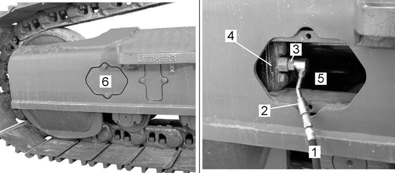
Danger!
Machines delivered up to september 2008 are possibly fitted with a lubricating nipple 3 showing two distinct hexagonal bearing areas.
To screw the grease nipple 3 in or out, always catch it at its rear part 3.1 (use a 27 mm wrench) and never at its front part 3.2
Loosening the nipple at its front hexagonal bearing area could cause the front part 3.2, to loosen and to be powerfully thrown out.
Tighten lubricating nipple 3 as soon as the desired track tension is obtained. After the adjustment procedure, drive the machine forwards and backwards and check the track tension again as described above.
5.13.5Cleaning the track components
Before working
Do not operate the machine if larger stones, pieces of wood or metal, wires or cables are wedged into the track components.
Dried or frozen mud and stones or other foreign bodies in track parts could result in considerable damage to the machine if the machine is operated or an attempt is made to free the machine using engine power.
In sub-zero temperatures, set the machine on wooden planks or logs to prevent the tracks becoming frozen to the ground.
Caution!
To avoid causing considerable damage to the frozen machine, never use force to tear it free.
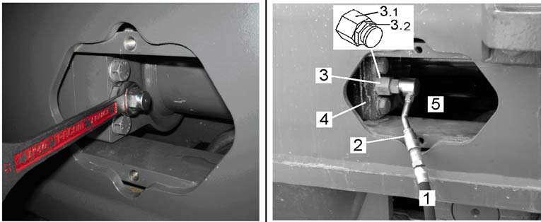
A frozen track can be freed by carefully heating the track pads.
At the end of a workday
Always clean the track components from dirt accumulation before stopping the machine.
Clean the gliding surfaces of the tension units from clinging dirt or sand and apply grease.
The machine can be supported and lifted slightly on each side with the attachment, so the tracks can be cleaned. Keep the bucket stick as vertical as possible when lifting one machine side.
Danger!
Never work from underneath on track components of the raised machine unless the track is securely blocked and supported with wooden beams. On a hard or flat soil the machine can slide away.
5.1424 V circuit
To insure trouble free operation of your excavator, the electrical system must be in good condition.
Its therefore important to inspect regularly the correct functioning and the good condition of the electrical system and to perform the following checks at the intervals given in the maintenance chart at the end of this manual.
5.14.1General checks on the 24 V electrical system
Check the correct function of the gauges and indicator lights daily, when starting the machine.
Always replace burnt-out fuses and bulbs immediately once the cause of the defect has been rectified.
It is forbidden to repair burn-out fuses, which must exclusively be replaced by original spare fuses with the same amperage.
Check for bare and damaged wires, which could cause damage to the electrical system or a fire. Check for loose, dirty or corroded connections. Immediately rectify defects such as loose connections, abraded cables or badly fastened clamps
5.14.2Batteries care
Danger!
Risk of injury due to formation of sparks.
When disconnecting batteries, always branch off the negative terminal (-) first and reconnect it last.
Avoid sparks and naked flame when charging batteries or working on the batteries.
Always wear protective goggles and gloves.
The batteries must always be kept clean to ensure that they are able to function perfectly.
Particular care should be taken to clean the pole ends and cable terminals A regularly and to then cover them with a thick layer of acidproof grease.
Danger!
Bent rubber hoses on the central gas outlet increase the risk of explosion! The hydrogen contained in the batteries should not be allowed to build up in the accumulator box and must be able to escape via the rubber hoses. The central gas outlet hoses must be routed without kinks.
Check the condition of the hoses B regularly, particularly after installing a battery.
The fluid level in the cells should be 10 to 15 mm above the top of the plate. Only distilled water is to be used for any refilling.
From time to time, measure the acid concentration using an acid tester. C When the battery is fully charged, the unit weight is 1.28 kg/l (31.5°Bé).
If the acid tester displays a lower value, the batteries is more or less unloaded and should be charged if necessary.
Care
5.14.3Batteries switch
Batteries Switch
Before starting any work on the electrical system, or before any welding work on the machine, switch the batteries switch to position 0.
Caution!
Take particular care with machines with built-in standstill heater. Only switch off the batteries switch when the standstill heater’s run-on is over.
Note!
Batteries can become flat if the machine is out of service for longer periods. Before laying up the machine for longer periods, switch the batteries switch to position 0 (off).
5.14.4Protection of the 24 V circuit during maintenance works
Disconnect the batteries when working on the electrical system or when carrying out electric arc welding on the machine.
When washing the machine, cover the electrical units (particularly the alternator, generator, cabling, electronic components and transmitters) to prevent water penetrating.
When cleaning the engine with a water / steam jet, do not subject transmitters such as oil pressure sensors to any direct jets.
If this happens, moisture could penetrate and lead to contact corrosion and the failure of the measuring function. Oil pressure sensors are not watertight due to the necessary presence of membrane ventilation.
5.15Heating/air-conditioning system
The machine has a combined heating / air-conditioning system as standard.
5.15.1Recirculated and fresh air filters
The air flow in the heating / air-conditioning system is reduced when the filters are dirty and this frequently results in the system icing up or shutting down.
–Remove and clean the recirculated and fresh air filter 1and3 every 500 operating hours.
–Shorten cleaning intervals when working in heavy dust conditions. –Do not operate the machine, even briefly, without these filters, since the heat exchanger 6 will otherwise quickly become blocked (see Fig. 5-77).
To clean and change the recirculated and fresh air filters: Push the backrest of the operator’s seat forwards to remove the recirculated air filter 1.
Open the quick-release fasteners 2 by a quarter turn. Remove the recirculated air filter 1
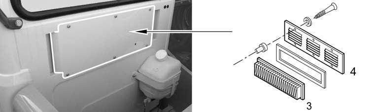
Remove the deflector 4. Remove the fresh air filter 3
Note!
Never wash the filter elements with hot water or a steam jet. If damaged or in a bad condition, replace the filter elements.
Blow out the filter elements 1 and 3 using compressed air or clean in cold or lukewarm water.
5.15.2Heating system
Carry out the following maintenance work on the heating system each year before the start of the heating period:
–Check the entire coolant circuit for leaks.
–Retighten the connection points for the coolant circuit, the hose connections on the heat exchanger, the seals on the shutoff valves and the hose clamps.
To vent the heating system:
To vent, unscrew the red cap of the vent valve over opening A (see arrow). Push in the valve to allow the air to escape.
To clean solenoid valve 5:
Annually, before the start of the heating period, remove and clean solenoid valve 5 (Y46) for the hot water supply.
Also clean the solenoid valve if heating performance is not sufficient. Rinse out the solenoid valve membrane with water.
Also ensure that the equalizing hole on the membrane is not blocked with dirt.
To check the heat exchanger:
Check the heat exchanger plates 6 annually for damage. Blow out with compressed air if dirty. Align the plates if necessary.
5.15.3Air-conditioning system
Switch on the air-conditioning system for approx. 10 minutes every 2 or 3 weeks, regardless of the season.
During the operating period, the following maintenance work is to be carried out every 500 operating hours:
To check the condensor: Check the condensor 2 for contamination.
If necessary, fold down the condensor 2 and blow out with compressed air from the inside (blower end) out.
Ensure that the condensor plates are clean.
If heavily contaminated, overpressure forms in the chiller circuit and the airconditioning system switches off automatically.
To check the A/C compressor:
Tighten the mounting screws 7 on the A/C compressor and the bracket on the engine.
To check the dryer-accumulator unit:
With the diesel engine running and the air-conditioning system switched on, check the refrigerant level in the inspection glass 10 of dryer-accumulator unit 9
Note!
If there is insufficient re frigerant, the white float 11 lays at the bottom of the inspection glass.
If the cooling effect is diminishing, have the system refilled by a refrigeration engineer.
Determine the degree of moisture of the desiccant in dryer-accumulator unit 9
To do this, observe the colour of the indicator pearl 12 in the inspection glass.
If the pearl is orange, the degree of moisture in the coolant circuit is OK. If, however, the pearl is not coloured, the dryer-accumulator unit is saturated with moisture. Change dryer-accumulator unit 9 immediately.
Perform a visual check on the condition of dryer-accumulator unit 9.
If it is observed that dryer-accumulator unit 9 is rusted or damaged (eg. on the panel fastening or on the hose connection), replace dryer-accumulator unit 9 (pressure tank).
In the two cases referred to above and at least once a year, have the dryeraccumulator unit 9 replaced by a fitter trained in refrigeration engineering.
The coolant circuit must be emptied, checked for leaks and refilled. Check for abrasion, replace and if necessary retighten the hose connections on the hoses.
Additional maintenance work:
The following maintenance work must also be carried out at least once a year by a fitter trained in refrigeration engineering:
Check the function of the fan motor 13 (M13).
Check the function of the ventilation flaps on the heating / air-conditioning system.
Check the electrical connections for correct positioning (good contact).
Check the electrical lines for abrasions.
Check the defrost thermostat 14 (B43) in the evaporator (function, correct positioning and for damage).
Check the function of the pressure switch B44 on the dryer-accumulator unit 9 (see Fig. 5-79).
5.16Greasing the machine
5.16.1The centralized lubrication system
The machine is serially fitted with a centralized lubrication system. With this system all or nearly all of the lube points of the machine which require at least daily lubrication are lubricated via an electrical driven grease pump which is turned on during machine operation.
Construction and operation of the centralized lubrication system. The centralized lubrication comprises two lubrication plants, U4-1 and U4-2, mounted at the top of the fuel tank.
Each complete
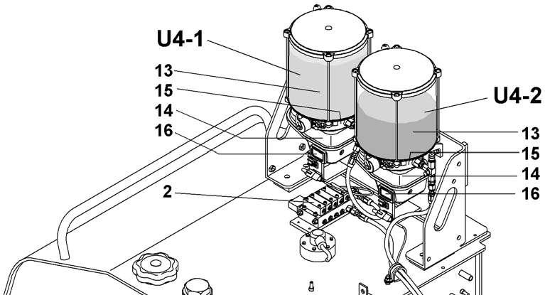
The grease delivered by the pump U4-1 is distributed to the different lubrication points LP in metered quantities, first via the main distributor 2 and further via the secondary distributors 3, 4, 5, ... mounted to the front of the upper carriage and to the working attachment.
During a lubricating procedure, all of the lube points connected to the system are lubricated one after the other in a predetermined sequence (progressive system).
The flow sequence and amount of lubricant for each lubrication point depend on the combination of the distributors and lubrication lines and on the piston sizes of the different distribution elements.
The pump U4-2 delivers the special grease for swing ring teeth lubrication. The grease quantity is metered in the distributor 9.
Lube points connected to the lubrication plant U4-1: –the ball bearing races of the swing ring, –all (or the most of) the lubrication points of standard working attachments. – the seat of the swing gear inside the uppercarriage structure. –the roller bearing of the output shaft of the swing gear.
Lube points connected to the lubrication plant U4-2: –the housing around the output pinion of the swing ring, which contains the grease reserves for the swing ring teeth lubrication,
Lube points which are not connected to the central lubrication system:
Caution!
When operating a machine and especially if it is fitted with a special working attachment, make sure to lubricate daily all the lubrication points which may be installed separately, i. e. which are not connected to the central lubrication system.
–On some backhoe attachments, some grease fittings may be installed separately in the area of the connector bracket and shifting lever for the digging tool. –With special attachments (telescopic stick, hydraulic offset boom, ...) some bearing points at the attachment or at the working tool are possibly not connected to the central lubrication system.
This bearing points have to be lubricated daily via separately mounted, red marked lubricating nipples and using a grease gun or a manual grease pump.
Notice!
The standard undercarriages of crawler excavators do not require daily lubrication. On undercarriages with special design necessitating regular lubrication (undercarriages with adjustable track width, ...) the lubrication points are not connected to the centralized lubrication. For description of the corresponding lubrication works, see the subgroups related to the special maintenance for these undercarriages.
5.16.2Operation of the full automatic system
Function of the automatic lubrication plants
After turning on the excavator the control light inside the touch S84-1 (resp. S84-2) and the green LED 17 of the integrated control unit 16 light up for approx. 1,5 sec. to show that the corresponding electric pump is operative.
.In each plant a lubrication procedure will begin automatically after a "cycle time" is over.
During lubrication, at each stroke of the dosing piston in the main distributor, the proximity switch B51 gives a pulse signal to the control unit 16, which stops the lubricating procedure as soon as the preadjusted number of strokes has been reached.
2 Main distributor
13 Grease container
15 Grease pump
17 LED green - in operation
19
14 Electric motor
16 Electronic control unit
18
26
Starting an additional lubrication procedure
If the lubrication plant U4-1 (resp. U4-2) is in working order, an additional lubricating procedure of the lube unit can be started any time by depressing either the push button S84-1 (resp. S84-2) on the rear control desk or the touch 19 on the respective motor housing.
Monitoring of the automatic lubrication system
During a lubrication procedure of the lubrication plant U4-1 (resp. U4-2), the control light inside the push button S84-1 (resp. S84-2) and the green LED 17 at the control unit are on continuously.
In case of a failure in a lubrication plant (no stroke signal delivered by the proximity switch B51 about 20 minutes after begin of a lubrication procedure) both LEDs 17 and 18 of the unit and the control light inside S84 will start blinking simultaneously.
The possible causes are:
–a plugged or kinked lubrication line, (in this case the grease will flow out of the relief valve 26), –a failure of the switch B51 or of its connecting wire, –the use of too viscous grease at very low temperatures, –not enough grease in the grease tank 13,
–a problem in the 24 V electrical circuit for the motor 14. Immediately locate and remedy the cause of the trouble.
5.16.3Emergency lubrication with defective lubrication system
In case the lubrication pump 15 does not work, all lubrication points connected to the centralized system may be lubricated via the lube fitting 25 using a lubrication gun.
For lubrication plant U4-1, press daily or per working shift approx. 250 cm3 grease into the fitting 25.
For lubrication plant U4-2, press daily or per working shift approx. 120 cm3 grease into the fitting 25
15 Grease pump
Caution!
25 Emergency lube fitting
For emergency lubrication via the lube fitting 25, it is imperative to have regard for the specific grease quality which is necessary for each lubrication plant.
5.16.4To refill a grease container
The grease level in the container 13 of the pump must be checked weekly, and if necessary, the container refilled.
Caution!
Since the both pumps deliver grease according to different specifications, it is essential to notice, for refilling, that the outer pump U4-2 is for swing ring teeth lubrication and that the pump U4-1 situated most inside is for the attachment bearings .
See the lubricant chart for grease specifications.
The refilling of the grease container should only be done via the special fitting 21.
Note!
Avoid refilling the container 13 via the upper cover 23, since it could create an air pocket in the container and cause the pump 15 to run dry.
13 Grease container
21 Fitting for filling pump
23 Cover
15 Grease pump
22 Grease fitting
31 Filling pump
Insert a grease cartridge in the special filling pump 31 (Id. No. 10009239).
Note!
The attached fiiling pump 31 for the lubrication plant U4-2 is marked with a label for gear teeth. When refilling, be carefull of employing always the correct filling pump, destined either for lubrication plant U4-1 or for lubrication plant U4-2.
Connect the pump to the fitting 21 push the whole content of the cartridge into the container 13
For indication of ordering number of grease cartridges, refer to subgroup "lubricants specifications".
If the special filling pumps 31 or the grease cartridges are not available: refill the container 13 through the grease fitting 22, using a grease gun.
5.16.5Changes in the lubrication circuit
Before you make any changes to the lubrication system (for example when changing the attachment configuration), always check with a LIEBHERR mechanic first. Never remove a line and close off an outlet, which is not being used, or the whole lubrication system would be blocked. Only plug an outlet after the line has been removed from the distributor and the necessary changes have been achieved at the corresponding distribution elements. This applies as well for main distributor 4 as for secondary distributors 5.
5.16.6Greasing the grab (optional extra)
The grab is not lubricated via the central greasing system. It must be regularly greased manually. The relevant oiling points are marked in red.
In normal use, each oiling point must be greased daily or per shift until clean grease flows out at the relevant bearing point.
When the machine is working hard, the greasing interval should be shortened accordingly.
Grease quality: see lubrication chart
5.17Quick-change systems
5.17.1Greasing the mechanical quick-change adapter (option)
The mechanical quick-change adapter is not lubricated via the central greasing system. The bearing points must be greased using the grease gun.
Grease the bearing points via the lubricating nipple using a grease gun. Grease quality: see “Lubricating and operating materials”
Note!
If the mechanical quick-change adapter is greased when the pin is drawn out, the hollow area between the locking pins fills with grease and the pins can no longer be reinserted.
Ensure that the locking pins are inserted when greasing.
5.17.2Hydraulic
quick-change adapter (option)
Greasing the quick-change adapter
The hydraulic quick-change adapter is not lubricated via the central greasing system. The bearing points must be greased using the grease gun.
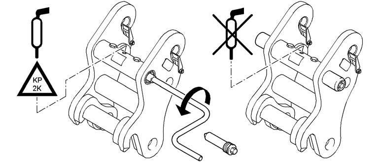
Grease the locking pins 1 via the lubricating nipple using a grease gun.
Note!
The hydraulic quick-change adapter cannot be sufficiently greased if the locking pins are drawn out.
Ensure that the locking pins are inserted when greasing.
Cleaning the sieve filter
The filter disc 12 in the bolt connections between the connecting hoses and the hydraulic cylinder must be checked for blockages and, if necessary, cleaned every 2000operating hours.
Remove the cover 20 and the screws 21 from the quick-change adapter.
Remove bolt connections and hydraulic hoses from the hydraulic cylinder 10
Screw out the outer mounting assembly 13 using a suitable tool (eg. a scribe).
Remove the filter disc 12, check and if necessary clean or replace it.
Place the filter disc 12 on the inner mounting assembly 11 and mount the outer mounting assembly 13
Connect bolt connections and hydraulic hoses to hydraulic cylinder 10.
Fasten the cover 20 with the screws 21 on the quick-change adapter.
5.17.3LIKUFIX (option) Cleaning LIKUFIX
The LIKUFIX hydraulic coupling system is mostly maintenance-free.
It is recommended that the system is cleaned at regular intervals and sprayed with lubricating varnish (see Workshop manual). This will prevent dirt adhering and icing up.
If the system is kept properly clean, the seals are very durable.
Replacing the sealing ring
Replacing the sealing ring
If leaks occur at the coupler plugs (A , see arrows), the sealing rings should be replaced.
Use a screwdriver to push down the sealing washer and lever out the defective sealing ring using a pointed object (B).
Press the new sealing ring together and place it on the sealing washer with the open side down (C).
Press down the washer as far as the groove, place the screwdriver in the middle of the sealing ring and move your hand away (D).
Allow the sealing ring to jump into the groove (E).
Remove the screwdriver (F).
The sealing washer must move upwards. If necessary, press the sealingring again until the sealing washer is flexible.
Check mounting bolts for tightness
5.18Check mounting bolts for tightness
The mounting bolts listed below must be regularly checked and retighten if necessary. See maintenance chart for the checks intervals.
Caution!
The mounting bolts for all the main components (especially those listed below), and for the hydraulic hoses and pipes must be replaced after every removal.
Notice: when installing bolts of size bigger than M40 the thread of the screw must be slightly coated with a MoS2 based grease. For these bolt sizes also grease the supporting surface of the bolt head, unless hereafter otherwise specified.
5.18.1Mounting bolts of the counterweight
The mounting bolts 1 (M42 - 10.9) must be torqued to 4500 Nm (3319 ft.lbs).
5.18.2Mounting screws of the swing ring
Check mounting bolts for tightness
The mounting screws 3 (M27 - 10.9) swing ring to undercarriage must be torqued to 1230 Nm (907 ft.lbs.).
On machines R974C with 100 mm-tower elevation, the pre-tightening torque of the stud screws 3 (M27 - 10.9) swing ring to undercarriage is 420 Nm (310 ft.lbs.) then the turning angle is 90°.
The mounting screws 4 (M27 - 10.9) swing ring to uppercarriage must be torqued to 1230 Nm (907 ft.lbs.).
5.18.3Mounting screws of the hydraulic oil and fuel tank
The mounting screws 5 (M20 - 10.9) must be torqued to 490 Nm (361 ft.lbs.)
5.18.4Mounting bolts of the swing gear and motor
The mounting bolts 6 (M24 - 10.9) of the swing gear must be torqued to 840 Nm (619 ft.lbs).
On machines R974C, torque mounting bolts 7 (M24 - 10.9) of the swing motor to 840 Nm (619 ft.lbs).
Check mounting bolts for tightness
5.18.5Mounting bolts central piece to side frames (option "removable side frames")
The bolts must be checked every 500 working hours, and if necessary re-tightened. The lower bolts M42 must be torqued to 4500 Nm (3319 ft.lbs).
The upper bolts M30 must be torqued to 1650 Nm (1217 ft.lbs).
5.18.6Fixing bolts of catwalks around the upperstructure
Every week visually check, and if necessary retighten the mounting bolts of the railer and also the ladder and suspended platform fixed around the upperstructure. Perform a general check of the tightening torque of these bolts every 1000 working hours. The bolts must be torqued to the following value:
Mounting boltsTightening torques DimensionClass[
5.19Drive unit brakes and swing gear brakes
Both the drive unit brakes and the swing gear brakes are spring-applied, pressurereleased multi-plate brakes. They are ventilated hydraulically and are fully sealed and integrated in the travel gear or swing gear transmission. Their usage purely as parking brakes makes them wear-free and therefore maintenance free.
5.20General maintenance points
5.20.1Replacing working parts
In addition to the normal maintenance and repair work that is to be carried out at the given intervals, the machine operator and maintenance personnel can also carry out the repairs referred to below:
–Replacing worn teeth on the bucket.
–Replacing defective sealing material on the pipe and hose system and on the hydraulic unit connections (not, however, on pressure relief valves which are lead sealed at the works).
–In addition, high pressure hoses, hydraulic lines and bolt connections on the hydraulic system can be replaced.
It should be noted that only original LIEBHERR replacement parts are to be used. This is particularly relevant for hoses and hydraulic lines, which must be preassembled at the works. For all other repairs, particularly when dismounting the ballast weight, works and dealership fitters are to be consulted.
5.20.2Checking or replacing the teeth on the bucket
Note!
Do not work with the machine if teeth on the bucket are missing or are heavily worn. With heavily worn teeth, considerably greater force will be required when using the bucket to penetrate the material to be excavated.
Determine the degree of wear of the teeth visually and at regular intervals (For intervall, refer to the maintenance chart).
Make the necessary to have heavily worn teeth replaced in good time, in any case early enough to prevent any damage occurring to the tooth fitting piece.
To attach and dismount the teeth:
Liebherr teeth system with flat locking wedge:
Fig. 5-97 Replacing the teeth
Use a hammer and ejector drift 1 to knock out the wedge 2 (A ). Remove the old tooth.
Place a new rubber wedge holder 3 onto the tooth holder (B). Push the new tooth onto the fitting piece.
Use the hammer to knock in the wedge 2 (C).
(New) Liebherr teeth system with tooth locking bolt round:
To remove an old tooth
1Tooth
3 Tooth locking bolt 4Latch
5 Expanded foam plug 10 Bolt blocking wrench
Take away the expanded foam plug 5 or the ground out of the square hole in the middle of the locking bolt 3
Set the bolt blocking wrench 10 (special tool Id. Nb. 10451202) onto the bolt 3 and turn counterclockwise to the stop (movement A - turn by approx. 30°).
Knock out the bolt 3 from the opposite side.
Take the tooth 2 off from the fitting 1 and remove the latching piece 4
To install a new tooth
Note!
Check the tooth locking bolt 3 and the latch 4 for good condition before reuse when installing a new tooth. Should this parts be distorted or strongly corroded, so they must be replaced by new ones.
Set the latch 4 in the hollow part of the tooth fitting 1 so that the flat side of the latch pushes against the fitting and slide the new tooth 2 over the tooth fitting 1.
Push the tooth locking bolt 3 all the way in.
Engage the bolt blocking wrench 10 into the square hollow in the middle of the bolt 3 and lock the bolt by turning the wrench clockwise by approx. 30° (when turning, the nose 3a of the bolt is enforced over the protrusion 4a of the latch).
Take the blocking wrench away and press a new expanded foam plug 5 into the middle of the locking bolt 3.
5.20.3Welding work on the machine
Welding work on all main components or structural parts serving the power transmission (such as the undercarriage, uppercarriage, attachment parts etc.) may only be carried out by the manufacturer or by an authorized workshop.
Caution!
If high currents flow through the bearings or sealing elements, these could be damaged.
When electric arc welding, attach the earthing cable of the welding tool as close as possible to the welding area, so that the welding current cannot flow over parts like the swing ring, articulations, bearings, bushings, rubber elements or seals.
Disconnect the batteries before starting any electric arc welding work on the machine.
Always disconnect the negative terminal (-) first and reconnect it last. Switch off the main battery switch!
On this machine fitted with electronic control system, you must also disconnect the components of the servo control circuit which are listed below.
Caution!
Electric arc welding on the machine can cause the destruction of not disconnected printing plates, this leading to a complete shutdown of the machine.
–disconnect the main control card U47 of the electronic servo control system situated below the driver’s cab..
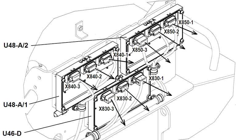
•Remove the cover under the cab.
•unplug both connectors X101 and X201.
–disconnect the control cards U46-D, U48-1 and U48-2 at the top of the hydraulic tank.
•Remove the protection hood at the upper side of the hydraulic tank.
•Unplug all the connectors X830, X840 and X850. Notice that the connectors are correctly identified, if necessary mark the connectors.
–disconnect the joystick units U20, U21 and the codage module U101 in the left control console.
These 3 components can be disconnected at the same time while unpluging the connector X733.
•remove the cover of the left control console.
•disconnect the connector X733.
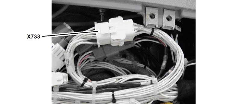
After completion of the welding works, carefuly reconnect the different components.
Note !
If electric arc welding is necessary on smaller and easily removable parts, preferably remove these parts from the machine to perform the welding works, seing the expenditure of the disconnections of the different electronic boards..
5.21Maintenance chart
Caution!
Careful maintenance can only be carried out when the machine is clean. In particular, visual checks such as crack testing are only possible on a clean machine.
Clean the machine before you start maintenance work (see also the chapter “Safe maintenance of the machine”, subheading “Cleaning and crack testing”).
Note
The daily maintenance work of the driver include the check of the proper function of hydraulic, electric and brake system before starting operation. He must also daily perform a visual check for leaks on the engine, hydraulic system, gears and track parts.
Carried Out
Diesel Engine And Splitterbox
Check oil level in engine
Check oil pressure and coolant temperature during operation
Check maintenance indicator of the air filter
Check and drain water separator on fuel filter (or when the corresponding symbol appears on the display)
If mounted, drain the condensation of the water separator of the particles filter system
Check coolant level
Drain off water and sediment at fuel tank
Check oil level in splitterbox
Check and clean watercooler and ventilator fan
Check condition of belt for A/C compressor and alternator installation
Replace lubricating oil filter cartridge (at least 1xyearly)
Replace engine oil (at least 1xyearly)1)
Replace splitterbox oil
Check oil, cooling and fuel systems for leaks and condition
Check anti-corrosion fluid / antifreeze in coolant, if necessary rectify the mixture concentration
Check / adjust valve clearance
Check mounting of engine control unit for good condition
Check detectors, transmitters and cable connectors for sound condition
Check the flap of the engine brake, grease the joints of the actuating cylinder
Check the shutting flap of the exhaust gas recirculation system
If mounted, carry out the maintenance of the water separator of the particles filter system
Replace fuel fine filter cartridge (or if power loss)2)
Replace fuel preliminary filter cartridge (or if power loss)2)
Check intake and exhaust systems for leaks and condition (first time at 500op. hours)
Maintenance
Work To Be Carried Out R 974 C
By maintenance personnel (machine owner)
First and only interval
Repeat interval
Special interval every 250hours
First and only interval Repeat interval
Check mounting screws of engine console, oil sump and splitterbox
Check heater flange at intake manifold (yearly at begin of cold season)
Replace air filter main element (according to maintenance indicator or warning symbol / at least once a year)
Replace air filter safety element (every thirdchange of main element / at least once a year)
Check air hoses between air filter and engine (at filter maintenance)
Replace coolant (every 2 years or every 3000 hours) (only for authorized specialist personnel)
Replace OS coolant (every 4 years or every 6000 hours) (only for authorized specialist personnel)
Replace oil separator (every 1000 hours or at least once a year)
Hydraulic System
Check oil level in hydraulic tank
Clean magnetic rods in return filters (daily during first 300. hours)
Replace servo filter element on control oil unit
Replace replenishing oil filter on swing pump
Check mounting screws of components
Check and clean hydraulic oil cooler and ventilator fan2)
Drain off water in hydraulic tank (when using environmentally friendly fluids, max. permissible water content is 0.1% , fit hydraulic system with bypass oil filter and take oil samples)
If mounted check return filter for hydraulic hammer for cleanliness, replace element if necessary
Perform an air bleeding procedure of the servo control chambers via the touch S248 (every 500 working hours and each time when necessary)
Replace filter elements in return filter (first time at 500hours)2)
Clean or replace filter element of leak oil filter (first time at 500hours)
Replacement necessary after max. 3 cleanings 2)
Check the degree of contamination of the bypass oil filter (optional equipment); if required, change the filter cartridge.
Check hydraulic system for leaks and function hours
First and only interval
Repeat interval
Check / adjust servo, primary and secondary pressures
If required, change the oil in the hydraulic system (to be carried out by specialist technical personnel; add oil through filter). For oil grades and change intervals, see fuels and lubricants, "Hydraulic oil".
Bleed servo system and hydraulic pumps (after replacing oil)
Replace breather filter on hydraulic tank2)
Check the elements of high pressure filters, if necessary clean or replace them
When using ester synthetic fluids, replace the hydraulic hoses every 4000 operating hours or at least every 4 years
ELECTRICAL SYSTEM
Check indicator lights and gauges on control panel when starting
Check head and floodlights
Check level and specific gravity of electrolyte in the batteries
Check and clean batteries terminals
Check the central vent tubes of the batteries for proper installation and damage.
Spray slip rings of electrical rotary connection (if mounted) with Cramolin contact spray
Check system and components for function
SWING GEAR TRANSMISSION
Check oil level and tightness
Replace oil (first time at 500op. hours)
Check function and operation of swing brake
Check swing gear transmission and hydraulic motor mounts
SWING RING
Check, if necessary retighten mounting screws
Check pinion gear mesh
TRAVEL GEAR
Check oil level and tightness
Check travel gear transmission and hydraulic motor mounts
Replace oil (at least every 2 years). Replace oil every 1000op. hours with dust intensive application or a travelling proportion greater than 12%.
Tracks
Visually check the track chains tension, retighten if necessary
Clean tracks (at the end of working day)
Check and tighten mounting screws of track pads and sprocket wheels
Clean and grease sliding surfaces of chain tensioners
Check idler wheels, carrier rollers and track rollers for leaks
Cab And Heater
Check level in reservoir for windshield washer, refill if necessary
Check function of heater (before start of cold season)
Check heating system for leaks
Check and grease locks and hinges on doors and windows
Check the warm water solenoid valve for function and chocking, clean it as necessary
AIR-CONDITIONING SYSTEM
Switch on air-conditioning system regularly (at least 1x every 14days)
Check the condensor for contamination, blow it out if necessary
Clean, if necessary replace both recirculated and fresh air filters in airco unit, reduce maintenance interval in very dusty conditions
Check mounting screws and compressor drive belt
Check the drier / receiver unit for moisture degree, coolant level and good condition (no rust), replace it if necessary
Check the condition of evaporator unit, clean as necessary
Check electrical wires for damage and for loose connections
Check pressure switch for function
Check efficiency of the air conditioner after opening the circuit, repairs or as necessary
Yearly replace the drier receiver unit, for the occasion check the whole circuit for leaks and replace refrigerating agent and refrigerator oil
Maintenance / inspection at operating hours
By maintenance personnel (machine owner)
First and only interval
Repeat interval
Work To Be Carried Out
R 974 C
By authorized specialist personnel First and only interval Repeat interval
Yearly have the function of the air flaps and of the defrosting thermostat checked by a refrigeration specialist.
UNDER / UPPERCARRIAGE, & ATTACHMENTS
Grease all lubrication points connected to the centalized lube system (actuate switch in cab with semi-automatic system or no action required with fully automatic system)
Manually grease all lubrication points not connected to the centalized lube system (as in digging bucket area if necessary, on special attachments or on special undercarriage)
Check bucket teeth visually for wear
Check all parts for cracks
Check mounting screws of counterweight and tanks for tightness
Check the screws of connections and the fittings on hydraulic hoses and pipes
Check and lubricate cover hinges and locks, check mounting and efficiency of cover lifting cylinders, replace as necessary
Check the lowering speed of the attachment~4 Sek.
Explain proper use and maintenance of the attachments to the operator
Ask the operator to lubricate the machine using the lubrication chart, explain defects and deficiencies
HYDRAULIC QUICK-CHANGE ADAPTER
Check function of optical and acoustic warning devices
Visually check drawn out position of locking pins
Check the hydraulic hoses, the cable tree and the safety latches on the load hooks of the quick change adapter for good condition
Lubricate locking pins
Clean the sieve filter in the fiitings of the hydraulic hoses
MECHANICAL QUICK-CHANGE ADAPTER
Visually check drawn out position of locking pins
Lubricate locking pins
Maintenance chart
1Depending on ambient temperature, fuel and oil qualities, the intervals for engine lube oil changes may be reduced.