4 minute read
Control and operation


Working with the machine
Note!
Turning on the float position of the boom cylinders can, depending on the kind of the material, facilitate the penetration of the shovel in the heap to be hollowed. When leveling out the working area, the bucket follows automatically the solid ground contour during the stick extension ( movement "b" controlled by the left joystick 3), and the shoveling up of the loosen material is made easier.
Control of the bucket or grapple cylinders
The bucket cylinder as well the grapple cylinders are controlled by the right joystick 3
Fig. 3-77 Operation of the bucket or grapple cylinders
Push the joystick 3 to the left e The bucket is tilted in, or the grapple closes. Push the joystick 3 to the right f. The bucket is tilted out, or the grapple opens.
Danger
Never allow anybody to guide the grapple by hand!
Combined movements
A diagonal movement of the joystick combines the corresponding movements of the working attachment. This makes it possible for all attachment movements to be actuated at the same time.
3.4.6Lowering the working attachment with the engine shut down
In an emergency, the attachment can be lowered also when the engine is not running.
Note
The attachment can be lowered thanks to a pressure accumulator mounted to the control oil unit. Due to the small volume of this accumulator only a limited number of movements can be actuated by the pilot control devices.
Only operate the joysticks in the directions for lowering the attachment. Only the movements resulting from the own weight of the attachment parts are possible.
Fig. 3-78 Lowering the attachment with shut down engine
Turn the ignition key to contact position 1
Actuate the desired movement(s) while deflecting the joysticks (eventually also the foot pedals in case of special attachment) until the equipment has lowered to the required position.
3.4.7Rotating, tilting, locking and unlocking a working tool
An additional hydraulic circuit must be activated to operate some specific working tools such as:
•a rotating grapple (A),
•a rotating bucket (B),
•a hydraulic quick-change adapter (C).
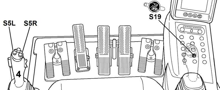
The medium pressure circuit is activated via the touch S19 on the main control unit.
The working tool is then actuated via the both push buttons S5L and S5R mounted at the top of the handle of the left joystick 4
Press the touch S19
The medium pressure circuit is activated. The LED of the touch is lighting.
Press the left push button S5L and keep it pressed. The working tool is actuated to the left (the grapple is rotated to the left, or the bucket is swivelled to the left, or the locking pins of the hydraulic quick-change adapter are driving out, ...).
Fig. 3-80 Actuation of working tools
Press the right push button S5R and keep it pressed. The working tool is actuated to the right (the grapple is rotated to the right, or the bucket is swivelled to the right, or the locking pins of the hydraulic quickchange adapter are retracted, ...).
The movement of the working tool is stopped as soon as the push button S5L or S5R is released.
Press the touch S19 again. The medium pressure circuit is deactivated and the working tool can not be actuated any more. The LED of the touch goes out.
Note!
With the option "Left joystick with proportional control" installed, the working tool can be actuated in a proportional way, while deflecting the mini joystick A185 on the left joystick to the left X- or to the right X+
Caution!
On machines destined to the North American market, and which are fitted with a lifting magnet, the rotating device is controlled by the push buttons S6L and S6R in the handle of the right joystick 3. Also see the section "joysticks" in this chapter.
3.4.8Lifting magnet control system (optional equipment)
A special circuit comprising an hydrostatic driven generator is installed as an option to supply the lifting magnet with the necessary electrical current. This special circuit is activated via the switch S46 the engine RPM can no longer be changed via the touches S228, S229 and S86 (this to avoid a possible lost of the load due to a demagnetization of the magnetic plate when the RPM become to low). the engine low idle automatic is deactivated and can no longer be turned on via touch S20
Press the touch S46 on the right rear control desk. the control lights inside the button is lighting. the generator is turned on. the engine RPM is automatically set to a fixed value (level 8 on P4).
The lifting magnet can now be controlled via the button S6L at the top of the right joystick handle.
Lifting magnet control system
Danger!
The magnet can lose its load in the event of a loss of current. Always ensure that noone is standing beneath the load. Do not press pushbutton S6L unintentionally.
Press the push button S6L at the top of the right joystick handle. The magnetic plate of the magnet is magnetized, the lifting magnet attracts and picks up the iron materials
Press the push button S6L again. The magnetic plate of the magnet is demagnetized, the iron materials are released by the magnet and fall down.
Caution!
For the machines with US Version (machines destined to the North American market), the lifting magnet is energized and de energized by the rocker switch S55 in the handle of the left joystick 4 instead of the push button S6L.
Press the rocker switch S55 up (b) to turn on the magnet.
Press the rocker switch S55 down (a) to release the load from the magnet.
3.4.9Control of additional attachments via the additional pedals
If necessary, select the mounted additional attachment in the menu "Set Option".
copyright by