6 minute read
Control and operation


Working with the machine
Note!
If the machine is used frequently or for long periods for hammer work, the hydraulic oil will be more contaminated than in usual conditions.
Adapt the maintenance intervals for hydraulic oil and for return filter cartridges to the work in heavy dust conditions.
3.4.10Commutation of control for an additional attachment (option)
Danger!
Risk of accident due to an unintentional movement by an uninformed machine operator!
When the commutation of the control is turned on, the correspondence between the controls and the working movements is changed. When the key is removed from the switch or when the touch is gone out, the machine can be operated only with the usual control system, installed at machine delivery.
It is the responsibility of the owner of the machine to grant an operator authorization to operate the machine with the activated special control system.
Caution!
Check out the functions of the additional controls when starting the machine, especially when a commutation of control is activated.
Standard control
Fig. 3-82 Commutation of standard control for an additional attachment
The additional attachment can be operated alternatively with the left double pedal or with the right joystick. The commutation of control can be activated with the key switch S114 on the rear right control desk.
Control and operation
Turn the key switch S114 to select the joystick position.
The additional attachment is now operated with the right joystick (movements to e and f).
The bucket tilt function is now operated with the left double pedal (m-k).
The key is locked in the switch S114.
Turn the key switch S114 to select the foot pedal position
The additional attachment is now operated with the left double pedal again. The key can be removed from the switch S114.
Proportional control
Mini joystick / Joystick
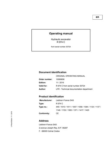
Fig. 3-83 Commutation of proportional control for an additional attachment
The additional attachment can be operated alternatively with the right mini joystick or with the right joystick. The commutation of control can be activated with the key switch S195 on the rear right control desk.
Turn the key switch S195 to select the joystick position
The additional attachment is now proportionally operated with the right joystick (movements to e and f).
The bucket tilt function is operated with the right mini joystick (movements to X- and X+).
The key is locked in the switch S195
Turn the key switch S195 to select the mini joystick position.
The additional attachment is proportionally operated with the right mini joystick.
The key can be removed from the switch S195 copyright by
Mini joystick / Pedals
Fig. 3-84 Commutation of proportional control for an additional attachment
The additional attachment can be operated alternatively with the right mini joystick or with the left pedals. The commutation of control can be activated with the touch on the right control desk.
Press the touch.
LED in the touch illuminates.
The additional attachment is proportionally operated with the right mini joystick.
Press the touch.
LED in the touch goes out.
The additional attachment is proportionally operated with the left pedals.
3.4.11Cut-off of attachment movements (option)
The movement cut-off restricts the movements of the boom cylinder or the stick cylinder. It enables:
–preventing repeated stopping over the mechanical buffers. –restricting the authorized working area (working height, working depth, maximal reach, minimal reach).
Danger!
The movement cut-off is not a safety device! It is only an assistance to the driver during an attachment movement near a prohibited zone!
Caution!
Danger of rocking motion of the machine and oscillations of the working tool!
Avoid fast attachment movements close to a cut-off point.
Note!
The movement is only cut off to enter into the prohibited zone. The movement to leave it remains possible.
Adjustment of the movement cut-off point
At the time of the cut-off, the attachment can enter into the prohibited zone in case of oscillations of the working tool, variations of its dimensions (open/close position) or attachment inertia.
Danger!
The machine driver is responsible for the adjustments precision!
You must keep a safety margin of at least 1.5 m from the prohibited zone.
As soon as the proximity switch detects the reflector, the movement is cut off. The proximity switch or the reflector position is adjustable depending on the configurations.
Bring the attachment into the desired cut-off position.
Loosen the nut 2 of the proximity switch 3 (or reflector).
Move the proximity switch 3 (or reflector) on the rail 4. Place it face to face with the reflector 1 (or proximity switch).
If the proximity switch 3 does not detect the reflector 1 when they are face to face, move them closer.
Retighten the nut 2 of the proximity switch 3 (or reflector). Check the actual cut-off position of the attachement.
If necessary, repeat the adjustment procedure and check the cut-off position again.
Note!
If the proximity switch and the reflector are difficult to be reached in the cut-off position:
Bring the attachment in a stretched and close to the ground position. Adjust approximately the cut-off point. Correct it by successive approaches until the desired cut-off position is reached.
Unlocking of movements cut-off
Danger!
Danger of personal injury and material damage in case of attachment movements within a prohibited zone by the movement cut-off!
The operator is in any case responsible for the accidents which can occur when the movement cut-off is unlocked.
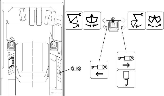
Fig. 3-86 Unlocking of movement cut-off
Bring the attachment into the cut-off position. Turn the key switch S54 to position I
Tilt up or down the switch S55 of the left joystick and keep it pressed. The cut-off of attachement movements is unlocked. It is possible to move the attachment within the prohibited zone as long as the switch S55 is kept pressed.
Turn the key switch S54 to position 0 The movement cut-off is actuated again.
If two movement cut-offs are fitted on the machine attachment, turn the key switch S54 to position II to unlock the second cut-off.
Note!
For the machines for the North-American market and fitted with a lifting magnet: Use the switch S5L of the left joystick to unlock the cut-off.
3.4.12Use of the excavator for lifting loads overhead
Under "lifting loads overhead" it is understood the lifting, transporting and unloading of loads requiring a securing method (ropes, chains, or other permitted lifting accessories) and where personnel are required to assist in securing and unloading the load. This includes, for example, the lifting and unloading of pipes, shaft-top supporting rings or containers.
Danger!
An hydraulic excavator may only be operated for lifting loads overhead if all the prescribed safety devices are present and functioning correctly.
In accordance with European standard EN 474-5, and so to guarantee the protections of the persons attaching or removing the loads during lifting operations, the machines used for lifting loads overhead must be equipped with the following safety devices:
– a load hooking system ensuring the safe attaching and removing of the loads (optional equipment)
Safe hooking systems include for example lifting hooks which are mounted in place of the bucket. Safety lifting hooks welded directly to the bucket are also allowed.
– an overload warning device (optional extra)
The overload warning device must alert the machine operator visually or acoustically if the permitted load value has been reached or exceeded, according to the rated lift capacity chart.
– a boom lowering control device (such as load check valves) to prevent unintentional lowering or dropping of the boom because of the weight of the load, which could happen if a line in this hydraulic circuit suddenly develops a leak (for example, should a hydraulic line break or a hose burst,...).
This boom lowering control device must correspond with the requirements of ISO 8643.
Such a boom lowering device can be installed as an option on all models up to R924C, it is serially installed on all models R934C and above.
– a rated lift capacity chart (commonly called load chart), attached inside the cab and within the view of the operator..
If the points referred to above are not or are only partially fulfilled, the machine may not be used for lifting loads overhead.
Every LIEBHERR hydraulic excavator can be fitted with all the safety devices required for lifting loads operation.
Danger!
Only employ sling ropes and accessories which are permitted for lifting operation, regularly checked and in good condition.
No person may fasten or unfasten a load without approval of the operator and this person may only approach the load from one side. The operator may only approve this action when the excavator has stopped and the attachment is not moving.
Never lift loads over people.
3.4.13Overload warning system (option)
Description
The overload warning system indicates to the machine operator when the maximum permitted load capacity is reached or exceeded.
The permitted load capacity depends on the configuration of the machine (undercarriage, working attachment). The maximum load capacity can be found on the load capacity chart in the operator's cab.
The load capacity values achieve a maximum of 75% of the tip load or 87% of the hydraulic lifting power according to ISO 10567.
The permissible load capacity is related to the factors that follow: –installation or dismantling of parts of the attachment –changing the tool attachment
The overload warning device does not release the machine operator from the responsibility of only lifting loads that are known and within the safe working load of the machine in accordance with the load lift chart.