ENGINE
L2501, WSM
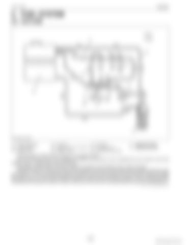
2. FUEL SYSTEM [1] OUTLINE
(1) Fuel Overflow Pipe (2) Injection Nozzle (3) Injection Pipe
(4) Fuel Tank (5) Injection Pump Air Vent Pipe (6) Injection Pump
(7) Fuel Filter (8) Fuel Feed Pump (9) Fuel Filter Air Vent Pipe
a: b:
Injected Fuel Flow Returned Fuel Flow
The fuel system of this tractor is shown in the diagram above. Fuel from the tank flows in the passage as shown by the arrows, and is injected from the nozzle via the fuel injection pump. Overflow fuel returns to the tank. The system includes filters and other concerns to protect it from entrance of air, water and dust. While the engine is running, fuel is fed into the injection pump (6) by the fuel feed pump (8) after passing through the fuel filter (7). The fuel camshaft actuates the injection pump and force-feeds fuel to the injection nozzle (2) through the injection pipe (3). Fuel is then sprayed through the nozzle into the combustion chamber. The fuel discharged after lubricating and cooling the injection nozzle is returned to the fuel tank (4) automatically through the overflow pipe (1). 9Y1211121ENM0003US0
1-M2
KiSC issued 09, 2014 A


