3 minute read
4. CHECKING AND ADJUSTING [1] ENGINE BODY

![6. SERVICING [1] STARTER](https://static.isu.pub/fe/default-story-images/news.jpg)
Compression Pressure
1.Run the engine until it is warmed up.
2.Stop the engine and disconnect the 2P connector from the stop solenoid in order to inject fuel.
3.Remove the fuel tank and all injection nozzles.
4.Set a compression tester (Code No. 07909-30208) with the adaptor to the nozzle hole (Nozzle hole thread size : M20 × 1.5).
5.Keep the engine stop lever at "Stop Position"
6.While cranking the engine with the starter, measure the compression pressure.
7.Repeat steps 4 through 6 for each cylinder.
8.If the measurement is below the allowable limit, apply a small amount of oil to the cylinder wall through the nozzle hole and measure the compression pressure again.
9.If the compression pressure is still less than the allowable limit, check the top clearance, valve and cylinder head.
10.If the compression pressure increases after applying oil, check the cylinder wall and piston rings.
NOTE
•Check the compression pressure with the specified valve clearance.
•Always use a fully charged battery for performing this test.
•Variances in cylinder compression values should be under 10 %.
Valve Clearance
Important
•Valve clearance must be checked and adjusted when engine is cold.
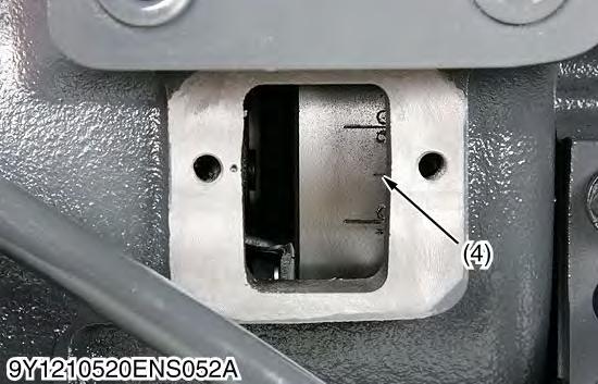
1.Remove the fuel tank, the head cover, the glow plugs and the timing window cover on the clutch housing.
2.Align the "1TC" mark line on the flywheel and center of timing window so that the No. 1 piston comes to the compression or overlap top dead center.
3.Check the following valve clearance marked with "" using a feeler gauge.
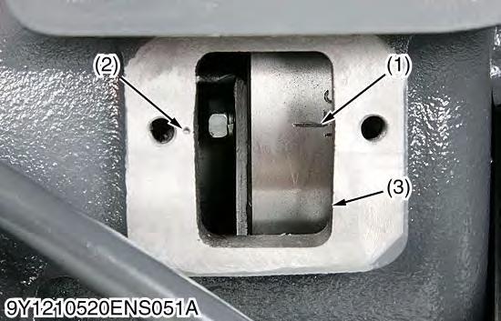
4.If the clearance is not within the factory specifications, adjust with the adjusting screw.
Note
•The "TC" marking line on the flywheel is just for No. 1 cylinder. There is no "TC" marking for the other cylinders.
•No. 1 piston comes to the T.D.C. position when the "TC" marking is aligned with the center mark of timing window on clutch-housing. Turn the flywheel 0.26 rad (15 °) clockwise and counterclockwise to see if the piston is at the compression top dead center or the overlap position. Now referring to the table below, readjust the valve clearance. (The piston is at the compression top dead center when both the IN. and EX. valves do not move; it is at the overlap position when both the valves move.)
•Finally turn the flywheel 6.28 rad (360 °) and align the "TC" marking line and the center mark of timing window. Adjust all the other valve clearance as required.
•After turning the flywheel counterclockwise twice or three times, recheck the valve clearance, firmly tighten the lock nut of the adjusting screw.
[2] LUBRICATING SYSTEM
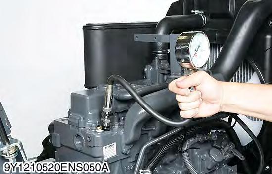
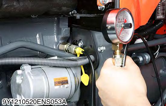
Engine Oil Pressure
1.Remove the engine oil pressure switch, and set an oil pressure tester (Code No. 07916-32032). (Adaptor screw size: PT 1/8).
2.Start the engine. After warming up, measure the oil pressure of both idling and rated speeds.
3.If the oil pressure is less than the allowable limit, check the following.
•Engine oil insufficient.
•Oil pump defective
•Oil strainer clogged
•Oil filter cartridge clogged
•Oil gallery clogged
•Excessive oil clearance
•Foreign matter in the relief valve
[3] COOLING SYSTEM
(When reassembling)
•After checking the engine oil pressure, tighten the engine oil pressure switch to the specified torque.
9Y1211121ENS0006US0
Fan Belt Tension
1.Measure the deflection (A), depressing the belt halfway between the fan drive pulley and alternator pulley at specified force 98 N (10 kgf, 22 lbf).
2.If the measurement is not within the factory specifications, loosen the alternator mounting screws and relocate the alternator to adjust.
9Y1211121ENS0007US0
Fan Belt Damage and Wear
1.Check the fan belt for damage.
2.If the fan belt is damaged, replace it.
3.Check if the fan belt is worn and sunk in the pulley groove.
4.If the fan belt is nearly worn out and deeply sunk in the pulley groove, replace it.
9Y1211121ENS0008US0
Thermostat Valve Opening Temperature
1.Suspend the thermostat in the water by a string with its end inserted between the valve and seat.
2.Heating the water gradually, read the temperature when the valve opens and leaves the string.
3.Continue heating and read the temperature when the valve opens approx. 6 mm (0.2 in.).
4.If the measurement is not within the factory specifications, replace the thermostat.
9Y1211121ENS0009US0
Radiator Cap Air Leakage
Caution
•When removing the radiator cap, wait at least ten minutes after the engine has stopped and cooled down. Otherwise, hot water may gush out, scalding nearby people.
1.Set a radiator tester (Code No. 07909-31551) and an adapter (BANZAI Code No. RCT-2A-30S) on the radiator cap.
2.Apply the specified pressure 80 kPa (0.9 kgf/cm2, 10 psi), and measure the time for the pressure to fall to 60 kPa (0.6 kgf/cm2, 10 psi).
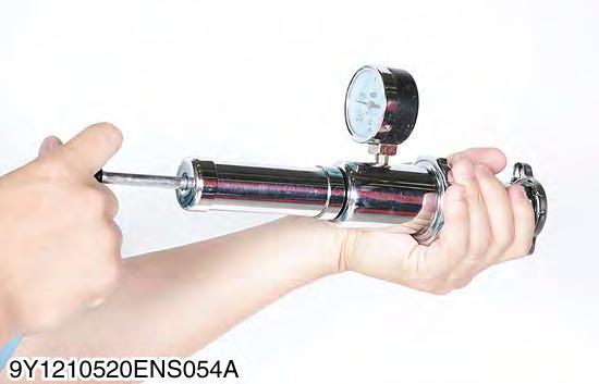
3.If the measurement is less than the factory specification, replace the radiator cap.
9Y1211121ENS0010US0
Radiator Water Leakage
1.Pour a specified amount of water into the radiator.
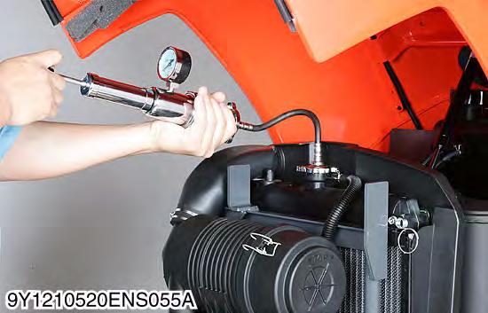
2.Set a radiator tester (Code No. 07909-31551) with an adaptor (BANZAI Code No. RCT-2A-30S) and raise the water pressure to the specified pressure.
3.Check the radiator and water pipes for water leak.
4.For water leak from the pinhole, replace the radiator or repair with the radiator cement. When water leak is excessive, replace the radiator.
5.For water leaf from water pipe, replace the water pipe. 9Y1211121ENS0011US0