6 minute read
TIMING GEARS, CAMSHAFT AND FUEL CAMSHAFT

![6. SERVICING [1] STARTER](https://static.isu.pub/fe/default-story-images/news.jpg)
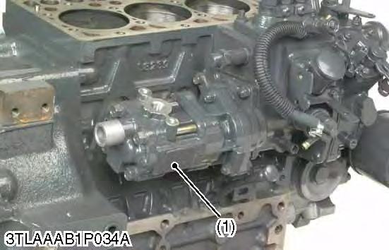
Hydraulic Pump
1.Remove the hydraulic pump mounting screws.
2.Detach the hydraulic pump (1).
9Y1211121ENS0038US0
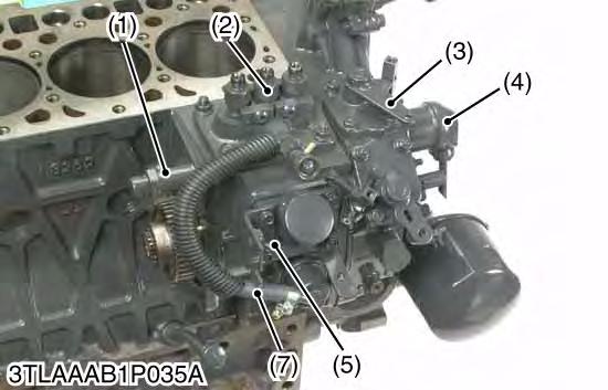
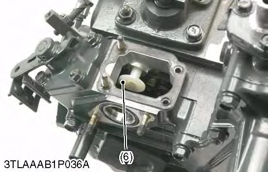
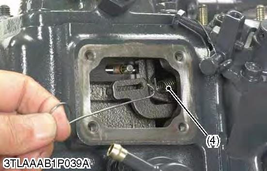
Injection Pump
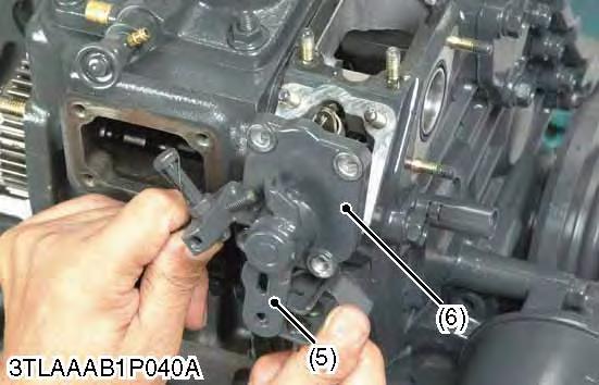
1.Remove the stop solenoid (4) and hi-idling body (1).
2.Remove the engine stop lever (3) and stop solenoid guide (6).
3.Remove the fuel hose (7), pump cover (5) and fuel injection pump assembly (2).
IMPORTANT
•Before removing the injection pump assembly (2), be sure to remove the stop solenoid (4), hi-idling body (1), engine stop lever (3) and stop solenoid guide (6).
(When reassembling)
•Before attaching the stop solenoid, hi-idling body and solenoid guide, install the injection pump first into position.
•Replace the hi-idling body gasket with a new one.
•Before fitting the stop lever to the gear case, install the solenoid guide first into position. Then attach the stop lever and use it to see if it functions well.
•Before fitting the idling limiter in place, attach the solenoid guide and the engine stop lever in their respective positions.
•When installing the stop solenoid, be careful to keep the O-ring in place.
•Be sure to insert the push rod of the stop solenoid into the hole at the center of the solenoid guide.
9Y1211121ENS0039US0
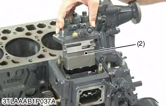
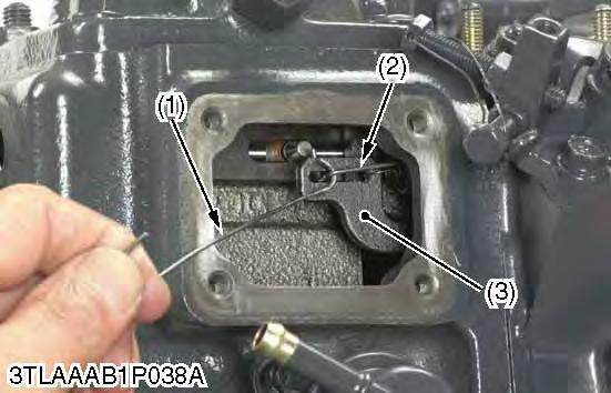
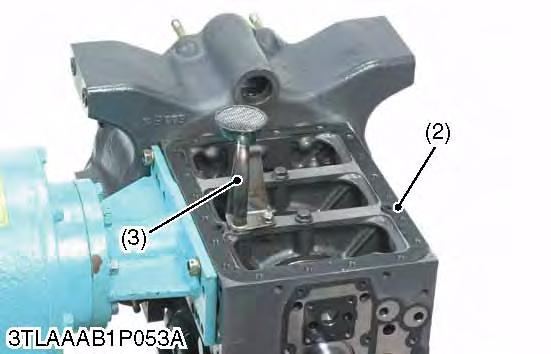
Governor Springs and Speed Control Plate
Note
•Specific tool (1) : 1.2 mm (0.047 in.) diameter hard wire with its end hooked, overall length 200 mm (7.87 in.). The tip of wire is bent like the hook to hang governor springs.
1.Remove the injection pump cover.
2.Remove the speed control plate mounting nuts and bolts.
3.Using the specific tool (1), undo the large governor spring (2) from the fork lever (3).
4.Using the specific tool, undo the small governor spring (4) from the fork lever (3).
5.Set the speed control lever (5) as the photo.
6.Take out the speed control plate (6) with care not to let the large and small governor springs come off this plate and fall into the gear case.
(When reassembling)
•Hook the small spring (4) first and then the large governor spring (2) on the speed control plate (6).
•Put the specific tool (1) from the injection pump side to catch the large governor spring (2). Keep this spring slightly extended and place the speed control plate (6) in its specified position.
•Using the specific tool (1), hook the small governor spring onto the fork lever (3).
Note
•Be careful not to stretch the small governor spring too long because otherwise it may get deformed permanently.
•Using the specific tool (1), hook the large governor spring (2) onto the fork lever (3).
•Make sure both the governor springs (2), (4) are tight on the fork lever (3).
•Apply and tighten up the two bolts and two nuts on the speed control plate (6).
•Check that the speed control lever (5) positions low idle, after assembling governor springs.
•Check that the speed control lever (5) returns to the high idle position rather than the low idle position, after moving the lever to the maximum speed position.
•Finally attach the injection pump cover in position.
9Y1211121ENS0040US0
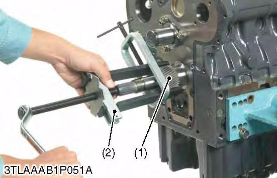
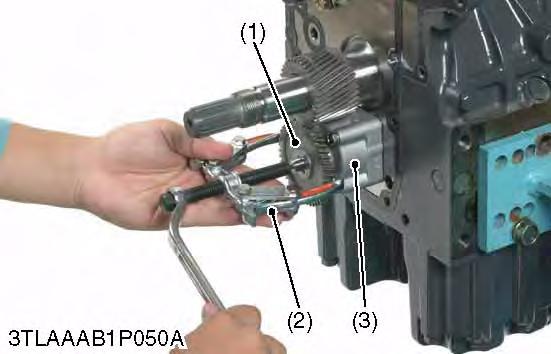
Fan Drive Pulley
1.Lock the flywheel not to turn using the flywheel stopper.
2.Remove the fan drive pulley mounting nut (1).
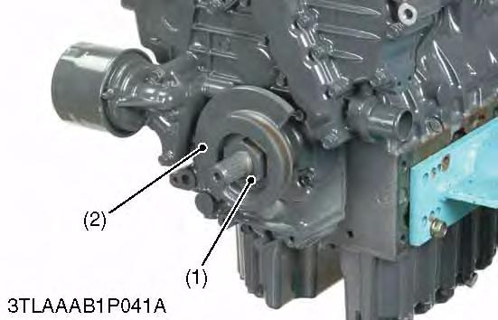
3.Remove the fan drive pulley (2) with gear puller (3).
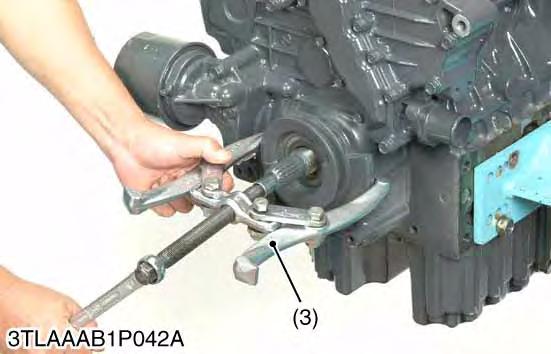
4.Remove the feather key. (When reassembling)
•Apply grease to the splines of coupling.
9Y1211121ENS0041US0
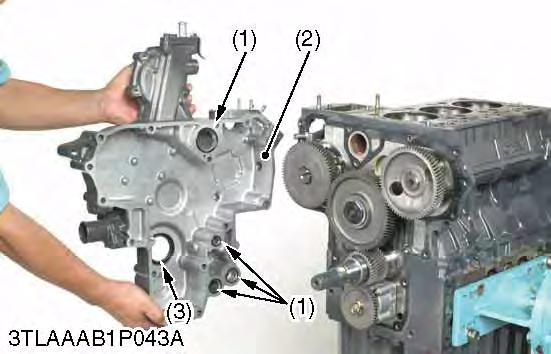
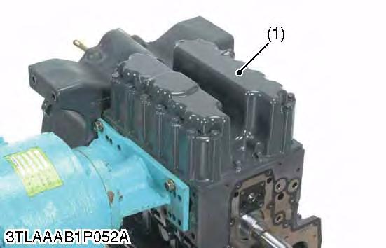
Gear Case
1.Remove the hour meter gear case.
2.Remove the gear case (2).
3.Remove the O-rings (1). (When reassembling)
•Apply liquid gasket (Three Bond 1215 or equivalent) to both side of hour meter gear case gasket.
•Check to see if there are four O-rings (1) inside the gear case (2).
•Apply a thin film of engine oil to the oil seal (3), and install it, noting the lip come off.
•Before installing the gear case gasket, apply a non-drying adhesive.
Crankshaft Oil Slinger
1.Remove the feather key.
2.Remove the crankshaft collar (3).
3.Remove the O-ring (2).
4.Detach the crankshaft oil slinger (1). (When reassembling)
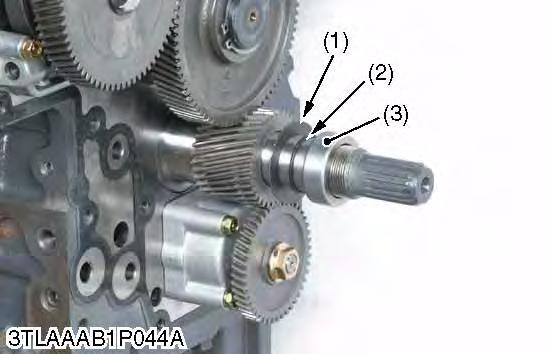
9Y1211121ENS0042US0
•Attach the crankshaft collar(3) after installing the gear case to the cylinder body.
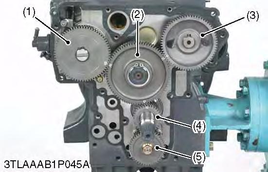
Idle Gear
1.Remove the external snap ring.
2.Detach the idle gear collar.
3.Detach the idle gear (2).
(When reassembling)
•Check to see each gear is aligned with its aligning mark. –Idle gear (2) and crank gear (4)
–Idle gear (2) and camshaft gear (3)
–Idle gear (2) and injection pump gear (1)
Camshaft
9Y1211121ENS0044US0
1.Remove the camshaft set bolts (2) and draw out the camshaft (1).
(When reassembling)
•When installing the idle gear, be sure to align the alignment marks on gears.
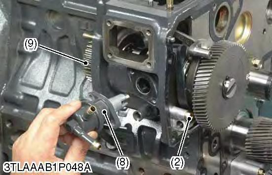
Fuel Camshaft and Fork Lever Assembly
9Y1211121ENS0045US0
1.Remove the fuel feed pump (8) and hydraulic pump drive gear (9).
2.Detach the fuel camshaft stopper (1).
3.Remove the three fork lever holder mounting screws (2).
4.Draw out the fuel camshaft assembly (5), (6) and fork lever assembly (3), (4), (7) at the same time.
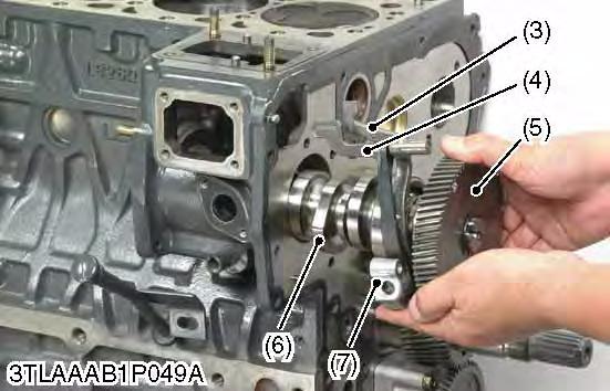
(When reassembling)
•After installation, check to see that the fork lever 1 (3) and 2 (4) are fixed to the fork lever shaft, and that they can turn smoothly in the holder (7).
9Y1211121ENS0046US0
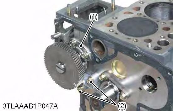
Oil Pump
1.Remove the nut.
2.Draw out the oil pump drive gear (1) with gear puller (2).
3.Remove the four oil pump mounting screws and the oil pump (3).
(1)Oil Pump Drive Gear (2)Gear Puller
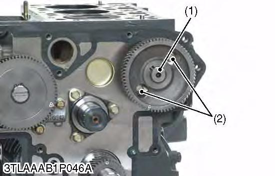
Crank Gear
9Y1211121ENS0047US0
1.Draw out the crank gear (1) with a puller (2).
2.Remove the feather key.
Pump (1)Crank Gear
[3] CONNECTING ROD AND PISTON
Oil Pan and Oil Strainer
1.Remove the oil pan mounting screws.
9Y1211121ENS0048US0
2.Remove the oil pan (1) by lightly tapping the rim of the pan with a wooden hammer.
3.Remove the oil pan gasket (2) if equipped.
4.Remove the oil strainer (3) and O-ring. (When reassembling)
•After cleaning the oil strainer (3), check to see that the filter mesh in clean, and install it.
•Visually check the O-ring, apply engine oil, and install it.
•Securely fit the O-ring to the oil strainer (3).
•Apply a liquid gasket (Three Bond 1215 or equivalent) to the oil pan side of the oil pan gasket (2).
•To avoid uneven tightening, tighten oil pan mounting screws in diagonal order from the center.
IMPORTANT
•Scrape off the old liquid gasket completely. Wipe the sealing surface clean using waste cloth soaked with gasoline.
•Cut the nozzle of the "liquid gasket" container at its second notch. Now apply liquid gasket 3.0 to 5.0 mm (0.12 to 0.19 in.) thick all over the contact surface. Apply liquid gasket also on the center of the flange as well as on the inner wall of each screw hole.
•Within 20 minutes after the application of fluid sealant, reassemble the components. Wait then for about 30 minutes, and pour oil in the crankcase.
9Y1211121ENS0049US0
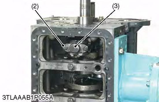
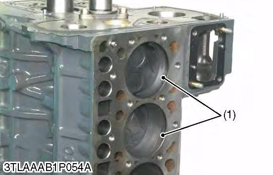
Pistons
1.Completely clean carbon (1) in the cylinders.
2.Remove the connecting rod cap (3).
3.Turn the flywheel and bring the piston to top dead center.
4.Draw out the piston upward by lightly tapping it from the bottom of the crankcase with the grip of a hammer.
5.Draw out the other piston in the same method as above. (When reassembling)
•Before inserting piston into the cylinder, apply enough engine oil to the piston.
•When inserting the piston into the cylinder, face the mark on the connecting rod to the injection pump.
IMPORTANT
•Do not change the combination of cylinder and piston. Make sure of the position of each piston by marking. For example, mark "1" on the No. 1 piston.
•Place the piston rings with their gaps at 0.79 rad (45 °) from the piston pin's direction as shown in the figure.
•Carefully insert the pistons using a piston ring compressor.
•When inserting the piston in place, be careful not to get the molybdenum disulfide coating torn off its skirt. This coating is useful in minimizing the clearance with the cylinder liner. Just after the piston pin has been press-fitted, in particular, the piston is still hot and the coating is easy to peel off. Wait until the piston cools down.
Tightening
(1)Carbon
(2)Connecting Rod Screw
(3)Connecting Rod Cap
(4)Connecting Rod
(5)Molybdenum Disulfide Coating in Piston Skirt
(6)Piston Ring Compressor
(A)Top Ring Gap
(B)Second Ring Gap
(C)Oil Ring Gap
(D)Piston Pin Hole
KiSC issued 09, 2014 A
Piston Ring and Connecting Rod
1.Remove the piston rings using a piston ring tool (Code No. 07909-32121).
2.Remove the piston pin (1), and separate the connecting rod (7) from the piston (2).
(When reassembling)
•When installing the rings, assemble the rings so that the manufacturer's mark (12) near the gap faces the top of the piston.
•When installing the oil ring onto the piston, place the expander joint (10) on the opposite side of the oil ring gap (11).
•Apply engine oil to the piston pin.
•When installing the piston pin, immerse the piston in 80 °C (176 °F) oil for 10 to 15 minutes and insert the piston pin to the piston.
•When installing the connecting rod to the piston, align the mark (8) on the connecting rod to the fan-shaped concave (9).
NOTE
•Mark the same number on the connecting rod and the piston so as not to change the combination.
(7)Connecting
(8)Mark
(9)Fan
(10)Expander
(11)Oil
(12)Manufacturer's
9Y1211121ENS0051US0