3 minute read
HST TYPE

![6. SERVICING [1] STARTER](https://static.isu.pub/fe/default-story-images/news.jpg)
Checking High Pressure Relief Valve Pressure
Caution
•When checking, park the machine on flat ground, apply the parking brake.
1.Remove the brake rod and the propeller shaft.
2.Remove the hex. socket head plug from P1 or P2 port. (P2 is for forward and P1 is for reverse.)
3.Assemble long adaptor C (07916-60831) and threaded joint (07916-50341) with the gasket between them.
4.Install the assemble long adaptor C and threaded joint to P2 (forward) or P1 (reverse) port (thread size : Rc (PT) 1/4).
5.Install the cable, threaded joint in relief valve set pressure tester and high pressure gauge to threaded joint in order.
6.Check to see that parking brake is applied.
7.Run the engine at maximum speed.
8.Place the range gear shift lever in N position.
9.Depress the HST pedal, and measure the high pressure relief valve pressure.
10.If the measurement is not within the factory specification, check the high pressure relief valve assembly. (See page 3-S44.) (When reassembling)
•Install the hex. socket head plug to the port with O-ring.
Condition
•Engine speed: Maximum IMPORTANT
•Measure quickly so that the relief valve may not be in operation more than 10 seconds.
NOTE
•Be sure to use a pressure gauge with over 39.2 MPa (400kgf/cm2, 5690 psi) capacity. 9Y1211121TRS0004US0
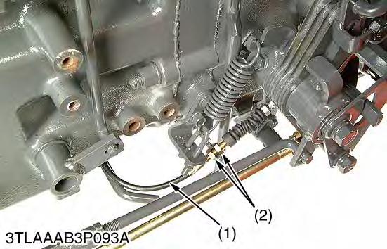
Checking Charge Relief Pressure CAUTION
•When parking, park the machine on flat ground, apply the parking brake.
1.Remove the brake rod and the propeller shaft.
2.Remove the hex. socket head plug from P port (1).
3.Assemble long adaptor C (07916-60831) and thread joint (07916-50341) with the gasket between them.
4.Install the assembled long adaptor C and thread joint to P port (1) (thread size : Rc (PT) 1/4).
5.Install the cable, thread joint in relief valve set pressure tester and low pressure gauge to threaded joint in order.
6.Place the range gear shift lever in N position.
7.Run the engine at maximum speed.
8.Release the HST pedal to set in neutral, and measure the charge pressure.

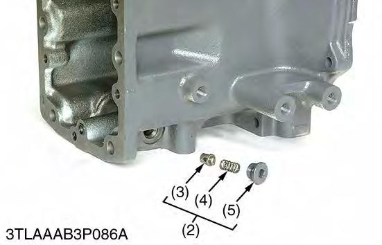
9.If the measurement is not within the factory specifications, check charge relief valve (2).
(When reassembling)
•Apply liquid lock (Three Bond 1324 or its equivalent) to the hex. socket head plug.
Condition
•Engine speed: Maximum
•Oil temperature: 40 to 60 °C (104 to 140 °F)
NOTE
•Use a new transmission oil filter.
•Be sure to use a pressure gauge with over 2.9 MPa (30kgf/cm2, 430 psi) capacity.
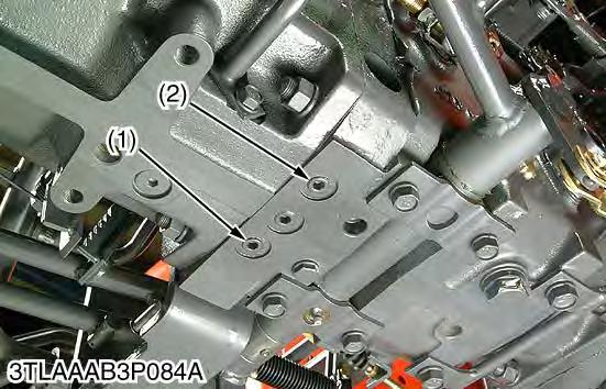
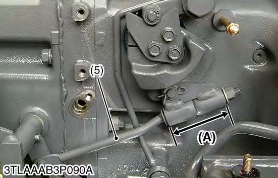
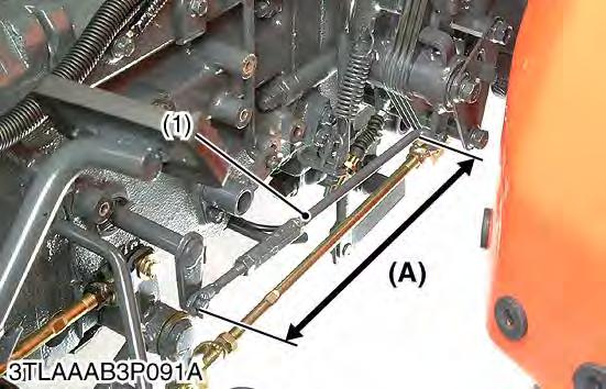
Adjusting Neutral
1.Disengage the front wheel drive lever. (Drive only rear wheels.)
2.Set the cruise control to "OFF" position. (HST pedal is neutral position.)
3.Check to see that the length (A) of HST neutral rod (5) is specified length.
If not, adjust as follows
Length (A): 73.0 to 74.0 mm (2.88 to 2.91 in.).
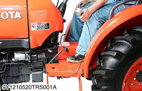
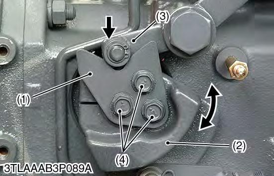
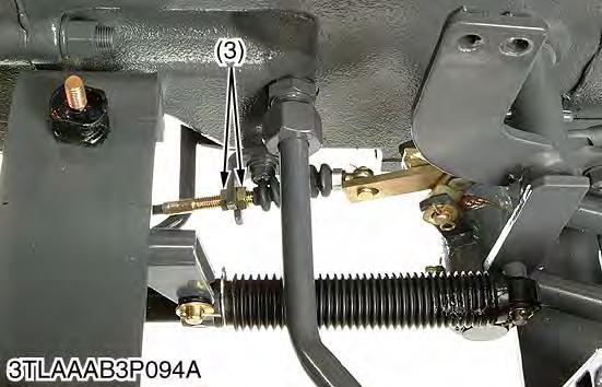
4.Lift the rear of the tractor so that the rear wheels are off the ground and run the engine at maximum speed and drive only rear wheels.
5.Slightly loosen the plate mounting screws (4).
6.Press the neutral holder arm (3) to the plate (1).
7.Then rotate the neutral holder (2) clockwise or counter clockwise until wheels stop completely.
8.Hold the neutral holder (2) and tighten the plate mounting screws (4).
NOTE
•Be sure to tighten the plate mounting screw with specified torque.
9Y1211121TRS0006US0
Adjusting HST Pedal and Stopper Bolt
NOTE
•Stop the engine when adjusting the pedal stroke.
•Be sure to adjust the HST neutral position.
1.Adjust the height (B) and (C) of the pedal stopper bolt (3), (4).
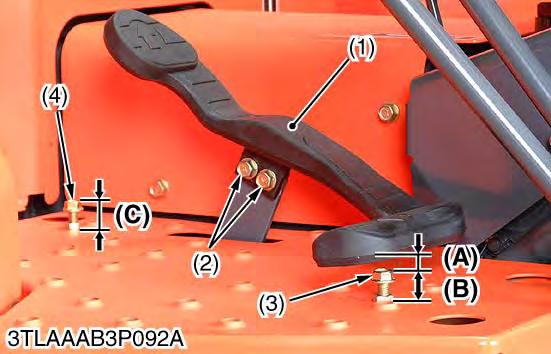
2.Loosen the HST pedal mounting screws (2).
3.Tighten the HST pedal mounting screws (2) so that the clearance (A) between HST pedal and stopper bolt (3) becomes factory specification at when HST pedal is fully depressed forward..
9Y1211121TRS0007US0
Adjusting PTO Wire
1.Check to see that the threaded portion of wire (3) rear side is set at center position. If not, set by lock nuts (2).
2.Set the PTO lever (1) at the "OFF" position "A".
3.The luck nut (4) is tightened in the direction of the arrow. Then stop it before the lever (5) moves.
4.Retighten the lock nut securely.
(1)PTO Lever
(2)Lock Nuts (Rear Side)
(3)PTO Wire
(4)Lock
9Y1211121TRS0008US0
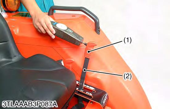
Checking Cruise Lever Operating Force (Option)
1.Push the cruise control lever (1) into maximum tied position. After that pull it 50 mm (2.0 in.) back.
2.Measure the force needed to move the cruise control lever back into the maximum position at the top of the lever grip (2).
3.If the force is not within the factory specifications, loosen the lock nut (4) and adjust the tension of cruise spring (3).
4.Retighten the lock nut securely.
9Y1211121TRS0009US0
Adjusting Cruise Control Rod (Option)
1.Set the cruise control lever to fully forward.
2.Adjust the cruise control rod (1) so that trunnion shaft may maximum incline forward.
9Y1211121TRS0010US0
Adjusting Cruise Control Release Linkage (Option)
1.Adjust the brake pedals play first.
2.Depress one of the brake pedals to make sure the cruise control is not released. Also depress both the brake pedals coupled together to make sure that the cruise control is released.
3.If the cruise control does not work as above adjust with release wire (1) as follows.
•Check to see that the threaded portion of the wire (1) rear side is set at the center position. If not, set by lock nuts (2).
4.In the end of the play of the brake pedal, adjust the lock nuts (3) so that slack of the wire may become 0.
•Confirm whether to move as above-mentioned 2. If not, adjust by lock nut (3).