HYDRAULIC SYSTEM
L2501, WSM
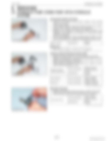
6. SERVICING [1] HYDRAULIC PUMP (THREE POINT HITCH HYDRAULIC SYSTEM) Housing Bore (Depth of Scratch) 1. Check for the scratch on the interior surface of the housing caused by the gear. 2. If the scratch reaches more than half the area of the interior surface of the housing, replace at pump assembly. 3. Measure the housing I.D. where the interior surface is not scratched, and measure the housing I.D. where the interior surface is scratched. 4. If the valves obtained in the two determinations differ by more than the allowable limit, replace the hydraulic pump as a unit. Depth of scratch
Allowable limit
0.09 mm 0.004 in.
(Reference) • Use a cylinder gauge to measure the housing I.D. 9Y1211121HYS0021US0
Clearance between Bushing and Gear Shaft 1. Measure the gear shaft O.D. with and outside micrometer. 2. Measure the bushing I.D. with and inside micrometer or cylinder gauge, and calculate the clearance. 3. If the clearance exceeds the allowable limit, replace the gear shaft and the bushings as a unit. Factory specification
0.020 to 0.081 mm 0.00079 to 0.0031 in.
Allowable limit
0.15 mm 0.0059 in.
Gear shaft O.D.
Factory specification
14.97 to 14.98 mm 0.5894 to 0.5897 in.
Bushing I.D.
Factory specification
15.000 to 15.051 mm 0.59056 to 0.59255 in.
Clearance between bushing and gear shaft
9Y1211121HYS0022US0
Side Plate Thickness 1. Measure the side plate thickness with an outside micrometer. 2. If the thickness is less than the allowable limit, replace it. Factory specification
2.48 to 2.50 mm 0.0977 to 0.0984 in.
Allowable limit
2.40 mm 0.0945 in.
Side plate thickness
9Y1211121HYS0023US0
8-S17
KiSC issued 09, 2014 A


