HYDRAULIC SYSTEM
L2501, WSM
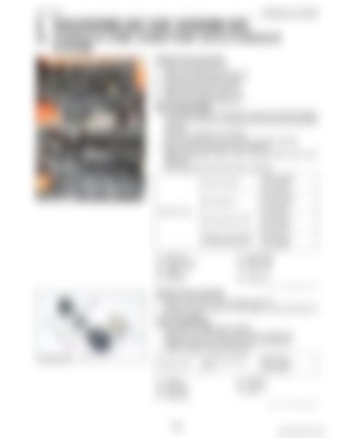
5. DISASSEMBLING AND ASSEMBLING [1] HYDRAULIC PUMP (THREE POINT HITCH HYDRAULIC SYSTEM) Hydraulic Pump Assembly 1. Remove the side cover (1). 2. Remove the steering joint shaft (5). 3. Disconnect the suction hose (3). 4. Disconnect the return hose (8). 5. Remove the delivery pipe (6), (7). 6. Remove the hydraulic pump (2). (When reassembling) • Lift the joint shaft (5) so that there should be a clearance (A) of more than 5 mm (0.2 in.) between the joint shaft (5) and flywheel housing. Then fit the support (4) in position. • Be sure to insert the screw into cut-out of joint shaft (5). • Apply grease to spline part of joint shaft (5). • Apply transmission fluid to the O-ring and take care not to damage it. • Wind seal tape to the joint of return hose (8). Screw (joint shaft)
23.5 to 27.4 N·m 2.4 to 2.8 kgf·m 18 to 20 lbf·ft
Screw (support)
23.5 to 27.4 N·m 2.4 to 2.8 kgf·m 18 to 20 lbf·ft
Delivery pipe joint screw
49 to 68 N·m 5.0 to 7.0 kgf·m 37 to 50 lbf·ft
Hydraulic pump assembly mounting screw and nut
24 to 27 N·m 2.4 to 2.8 kgf·m 18 to 20 lbf·ft
Tightening torque
(1) (2) (3) (4) (5)
Side Cover Hydraulic Pump Suction Hose Support Joint Shaft
(6) Delivery Pipe (7) Delivery Pipe (8) Return Hose (A) Clearance 9Y1211121HYS0007US0
Hydraulic Pump Assembly 1. Remove the pump cover mounting screw (7). 2. Remove the drive gear (6), driven gear (2) and side plate (3) from the casing. (When reassembling) • Take care no to damage the gasket. • Align the hole of the pump cover (4) and casing 2 (5). • Install the side plate, noting its location and direction. • Install the gears, noting its direction. Tightening torque
(1) (2) (3) (4)
Casing 1 Driven Gear Side Plate Pump Cover
Pump cover mounting screw
40 to 44 N·m 4.0 to 4.5 kgf·m 29 to 32 lbf·ft
(5) Casing 2 (6) Drive Gear (7) Screw 9Y1211121HYS0008US0
8-S9
KiSC issued 09, 2014 A


