TRANSMISSION
L2501, WSM
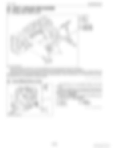
[4] SHIFT LINKAGE MECHANISM (1) Range Gear Shift Lever (1) (2) (3) (4)
Shift Lever Rod Shift Arm Shift Fork
A: B: C:
L speed range M speed range H speed range
The links from the shift lever (1) to the shift fork (4) are connected as shown in the figure. When the shift lever (1) is moved to the "A" side, the shift fork (4) is moved to the "A" side by means of the rod (2), and shift arm (3), changing the shift arm to the L speed position. When the shift lever (1) is moved to the "C" side, the shift fork (4) is moved to the H speed position. 9Y1211121TRM0022US0
(2) Front Wheel Drive Lever The shift lever (1) is connected directly to the shift fork (2). When the shift lever (1) is moved to the "A" side, the shift fork (2) is also moved to the "A" side, then the front wheel drive is "Engaged". When the shift lever (1) is moved to the "B" side, the front wheel drive is "Disengaged". (1) Shift Lever (2) Shift Fork (3) Shifter Gear
A: B:
Engaged Disengaged 9Y1211121TRM0008US0
3-M18
KiSC issued 09, 2014 A


