TRANSMISSION
L2501, WSM
[3] CRUISE CONTROL (OPTION)
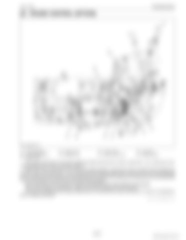
(1) Connecting Shaft (2) Cruise Adjusting Rod (3) Release Wire
(4) Cruise Lever 1 (5) Release Lever
(6) Cruise Lever 2 (7) Cruise Control Lever
(8) Lever Rod (9) Release Spring
The cruise control lever (7) and HST pedal are linked with the lever rod (8), cruise lever 1 (4), cruise lever 2 (6), cruise adjusting rod (2) and connecting shaft (1). When the cruise control lever (7) is moved to forward direction, cruise lever 2 (6) is moved to arrow direction by the lever rod (8). The cruise lever 1 (4) is moved forward by being pushed to the cruise lever 2 (6), and cruise adjusting rod (2) is pulled backward. Because cruise adjusting rod (2) and the HST pedal are connected by the connecting shaft (1), the HST pedal is moved and HST becomes forward position. The cruise control can be returned to neutral automatically when brake pedals are depressed. When brake pedals are depressed, release wire pull the release lever (5) to forward. As result, the holding force of cruise control lever (7) is lost and the cruise control lever (7) return to neutrality by force of release spring (9). 9Y1211121TRM0021US0
3-M17
KiSC issued 09, 2014 A


