ENGINE
L2501, WSM
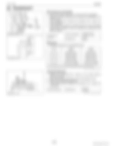
[4] CRANKSHAFT Side Clearance of Crankshaft 1. Set a dial indicator with its tip on the end of the crankshaft. 2. Measure the side clearance by moving the crankshaft to the front and rear. 3. If the measurement exceeds the allowable limit, replace the thrust bearings. 4. If the same size bearing is useless because of the crankshaft journal wear, replace it with an oversize one referring to the table and figure. Crankshaft side clearance
Factory specification
0.15 to 0.31 mm 0.0059 to 0.012 in.
Allowable limit
0.5 mm 0.02 in.
(Reference) • Oversize dimensions of crankshaft journal Oversize
0.2 mm 0.008 in.
0.4 mm 0.016 in.
Dimension A
54.50 to 54.70 mm 2.146 to 2.153 in.
54.6 to 54.8 mm 2.150 to 2.157 in.
Dimension B
26.20 to 26.25 mm 1.032 to 1.033 in.
26.40 to 26.45 mm 1.040 to 1.041 in.
Dimension C
2.8 to 3.2 mm radius 0.11 to 0.12 in. radius
2.8 to 3.2 mm radius 0.11 to 0.12 in. radius
The crankshaft journal must be fine-finished to higher than Rmax=0.4S. 9Y1211121ENS0087US0
Crankshaft Alignment 1. Support the crankshaft with V blocks on the surface plate at both end journals. 2. Set a dial indicator with its tip on the intermediate journal. 3. Measure the crankshaft alignment. 4. If the measurement exceeds the allowable limit, replace the crankshaft. Crankshaft alignment
Allowable limit
0.02 mm 0.00079 in. 9Y1211121ENS0088US0
1-S66
KiSC issued 09, 2014 A


