ENGINE
L2501, WSM
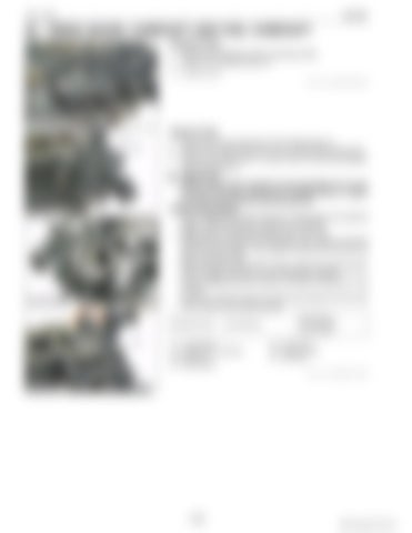
[2] TIMING GEARS, CAMSHAFT AND FUEL CAMSHAFT Hydraulic Pump 1. Remove the hydraulic pump mounting screws. 2. Detach the hydraulic pump (1). (1) Hydraulic Pump 9Y1211121ENS0038US0
Injection Pump 1. Remove the stop solenoid (4) and hi-idling body (1). 2. Remove the engine stop lever (3) and stop solenoid guide (6). 3. Remove the fuel hose (7), pump cover (5) and fuel injection pump assembly (2). IMPORTANT • Before removing the injection pump assembly (2), be sure to remove the stop solenoid (4), hi-idling body (1), engine stop lever (3) and stop solenoid guide (6). (When reassembling) • Before attaching the stop solenoid, hi-idling body and solenoid guide, install the injection pump first into position. • Replace the hi-idling body gasket with a new one. • Before fitting the stop lever to the gear case, install the solenoid guide first into position. Then attach the stop lever and use it to see if it functions well. • Before fitting the idling limiter in place, attach the solenoid guide and the engine stop lever in their respective positions. • When installing the stop solenoid, be careful to keep the O-ring in place. • Be sure to insert the push rod of the stop solenoid into the hole at the center of the solenoid guide. Tightening torque
(1) (2) (3) (4)
Hi-idling body
Hi-idling Body Injection Pump Assembly Stop Lever Stop Solenoid
45 to 49 N·m 4.5 to 5.0 kgf·m 33 to 36 lbf·ft (5) Pump Cover (6) Solenoid Guide (7) Fuel Hose 9Y1211121ENS0039US0
1-S44
KiSC issued 09, 2014 A


