ENGINE
L2501, WSM
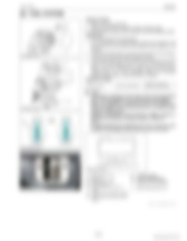
[4] FUEL SYSTEM Injection Timing 1. Remove the stop solenoid. 2. Remove the fuel tank, injection pipes and glow plugs. 3. Set the speed control lever to maximum fuel discharge position. (Reference) • Turn the flywheel with screwdriver. 4. Turn the flywheel counterclockwise (facing the flywheel) until the fuel fills up to the hole of the delivery valve holder for 1st cylinder. 5. Turn the flywheel further and stop turning when the fuel begins to flow over, to get the present injection timing. 6. (The flywheel has mark 1TC and four lines indicating every 0.09 rad (5 °) of crank angle from 0.17 rad (10 °) to 0.44 rad (25 °) before mark 1TC) Calculate the angle which the center of the window points out. If the calculation differs from specified injection timing, add or remove the shim to adjust. (Injection Timing) Injection timing
Factory specification
0.0568 to 0.0829 rad 3.25 ° to 4.75 ° B.T.D.C.
NOTE • The sealant is applied to both sides of the soft metal gasket shim. The liquid gasket is not required for assembling. • Shims are available in thickness of 0.20 mm (0.0079 in.), 0.25 mm (0.098 in.) and 0.30 mm (0.012 in.). Combine these shims for adjustments. • Addition or reduction of shim (0.05 mm, 0.002 in.) delays or advances the injection timing by approx. 0.009 rad (0.5 °). • In disassembling and replacing, be sure to use the same number of new gasket shims with the same thickness.
(1) (2) (3) (4) (5)
Speed Control Lever Stop Lever Delivery Valve Holder "1TC" Mark Line 2-Holes: 0.20 mm (0.0079 in.) (Shim) (6) 1-hole: 0.25 mm (0.098 in.) (Shim) (7) Without hole: 0.30 mm (0.012in.) (Shim)
A: B: C:
To STOP Position To Max. Speed Position Stop Lever in Free Position
a:
0.267 ± 0.03 rad (15.3 ± 2 °)
9Y1211121ENS0012US0
1-S15
KiSC issued 09, 2014 A


