Assembly process No.
Installation of grease hose of blade joint (if equipped) (1/2)
A-14
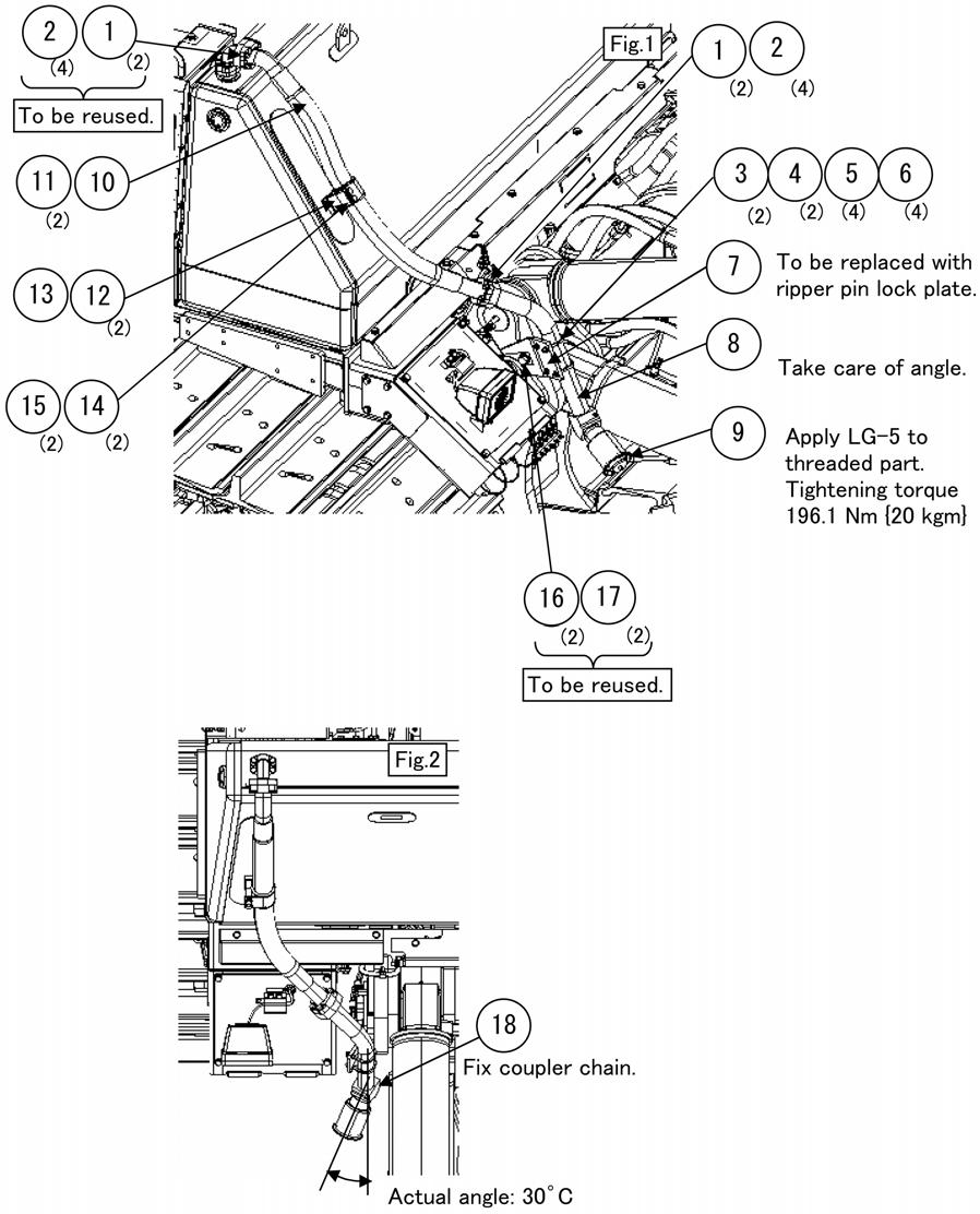
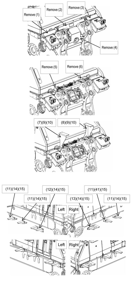
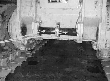
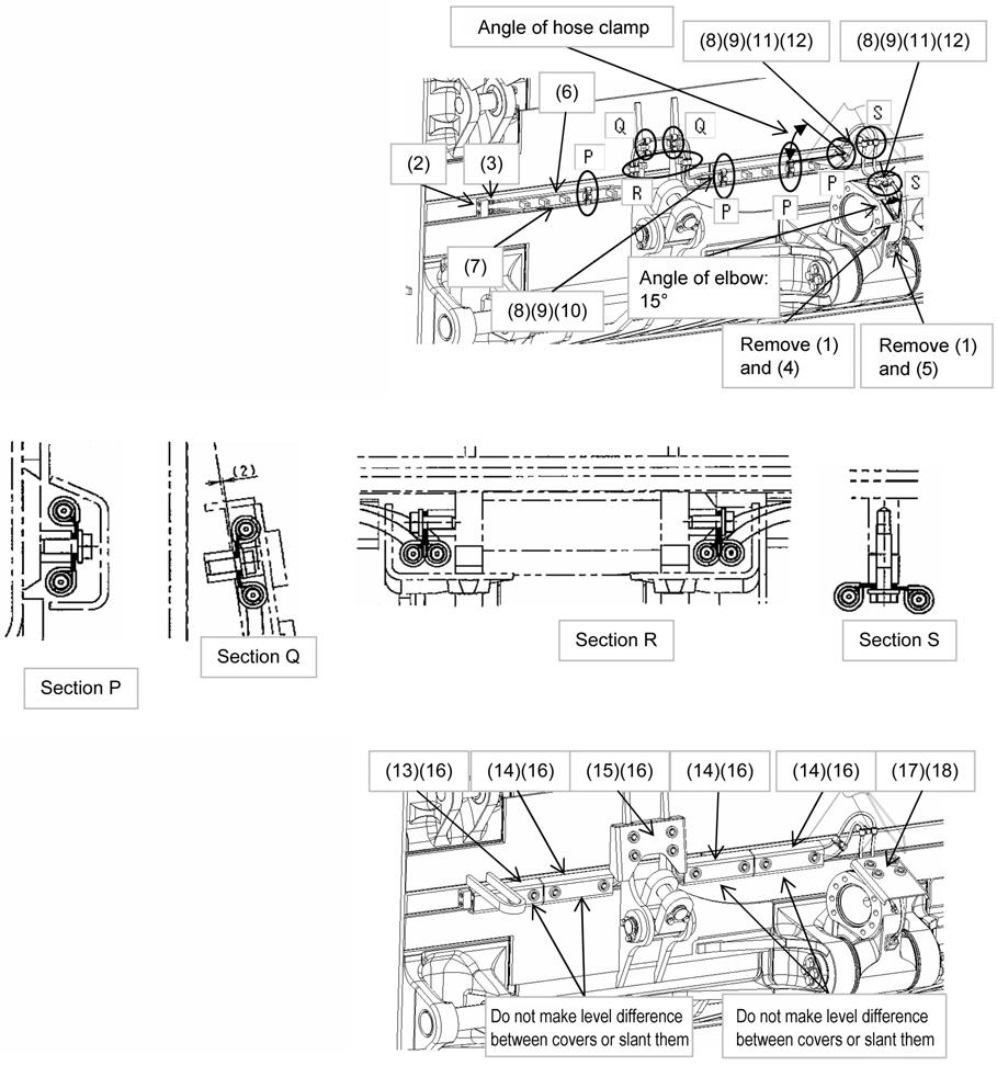
1. Installation of grease piping of blade (1) Remove nipple (1) installed to the center link. (2) Install nipples (2) and (3) to the bosses at the left back of the blade. (3) Install elbow (3) and nipple (4) to the center link. (4) Install hoses (5) and (6) by using clamps (7), (8), (9), (10), (11), and (12). (5) Connect hoses (6) and (7) to nipple (3), elbow (4), and nipple (5).
2. Installation of hose covers (1) Install covers (13), (14), and (15) by using bolts (16). (2) Install cover (17) by using bolts (18). When installing covers (13) and (14), do not make a level difference or slant them. No. Part name
Part No.
Q’ty
Part No.
Q’ty
1 Nipple
07020-00000
2
For transportation 10 Bolt
Remarks
No. Part name
01024-81230
6
2 Nipple
07020-00000
2
11 Bolt
01024-81250
2
3 Nipple
203-62-21740
2
12 Spacer
195-33-11220
2
4 Elbow
198-68-11341
1
13 Cover
195-68-11621
1
5 Nipple
198-68-11640
1
6 Hose
198-68-11820
1
3,100 mm
14 Cover
195-68-11631
3
15 Cover
195-68-11661
1
7 Hose
195-68-12240
1
2,900 mm
8 Clamp
04434-51712
20
16 Bolt
01024-81230
12
17 Cover
195-68-11160
1
9 Bushing
07095-20211
20
18 Bolt
01024-81280
4
100
Remarks