4 minute read
Table of tools for field assembly

No.Tool name Specification Q'ty Remarks 1Air compressor Min. 0.69 MPa – 15 m³/min 1 2Pneumatic hose and cou- Hose length: 30 m 1 setFor air compressor pler (for pneumatic tools) Coupler must fit impact wrench and oil feed pump. 3Crane truck Lifting load: 50 ton 2 Lifting load: 25 ton 1 4Welder 2For welding blade spill guard (If equipped) 5Chain lever hoist Rated load 1.5 ton 1JIS B8819 or equivalent (Chain block) Rated load 3.2 ton 1 Rated load 6.3 ton 1 6Wire rope sling ø 36 × 6 m 4Specification: JIS B8817 or equivalent ø 20 × 5 m 2 ø 12 × 2 m 4 7Belt sling 25 mm wide × 3 m 2Specification: JIS B8818 or equivalent (made of synthetic fibers) 50 mm wide × 3 m 1 8Hydraulic wrenchMin 5,890 Nm {600 kgm} 1Mainly for master link bolt 9Hydraulic wrench socketWidth across flats: 46 1 unit For master link bolt each 10Extension bar T 38.1 × L300 1 11Air impact wrenchSee No. 41 12Socket for impact wrenchWidth across flats: 19, 22, 24, 27, 1 unit Must fit impact wrench No. 41. 30, 32, 36, 41, 46, 50 each 13Torque wrench Tightening capacity 1Impact wrench socket may be used if it 588 Nm {60 kgm} fits. Tightening capacity 1 1,370 Nm {140 kgm} Tightening capacity 1 2,060 Nm {210 kgm} 14Soket for torque wrenchWidth across flats: 32, 36, 41, 461 unit each 15Eyebolt M12, Using load: 220 kg 4 M16, Using load: 450 kg 2For blade center link 16Shackle SD22 4Specification symbols are quoted from BC36 2 JIS B2801 SB44(T) 2 17Sledge hammer Double-headed: 4.5 kg (10 lbs)1 18Pinch bar (Lever)ø 25 × 900 mm 1JCMAS P018 or equivalent, Note 1) 19Thread repair tapM33 × Pitch 2 1For master link M30 × Pitch 3 1 M24 × Pitch 3 1 20Jack Screw type, Using load: 15 ton2For assembling track frame 21Single ended wrenchNominal width across flats (mm) 2 units For tightening hydraulic hose mouthpiece 17, 19, 22, 24, 27, 30, 32, 36, 41, each nut 46, 50 22Lubricating oil and greaseSee assembly procedures A-3 — and A-23. 23Anti-seize compoundMolybdenum disulphide grease 200 gSee coating material list. (LM-P) 24Cleaning oil For removing preservative40 l 25Paint remover For removing phthalate resin 5 l coating 26Paint for repair See coating material list 3 units each
No.Tool name Specification Q'ty Remarks 27Glass cleaner Cleaning liquid 1For cleaning operator cab windshield (commercially available) glass 28Cloth Bunch 1 kg 29Adhesive cloth tapeWidth × Length × Color 1 roll 50 mm × 25 mm × Not specified 30Plastic tube (Vinyl tube)8 mm inside diameter × 1 mm 1For checking airtightness (internal presthick × 3 m long, soft, transparent sure) of operator cab 31Oil feed pump Manual or pneumatic 1 32Oil mug Capacity: Approx. 5 l 1 33Drain oil receiver 1,000 × 700 × 150 (mm) 2 units (made of steel sheet) 700 × 400 × 150 each 300 × 300 × 100 34Stand for high lift work2 m high, with stair and handrail2 35Safety belt Waist belt type Same as number of workers 36Safety glasses Same as number of workers 37Stand For attached tool drawing 1Front (for setting machine) For attached tool drawing 1Rear 38Steel plate liner (for install- 1,000 × 500 (mm) 4With lifting hook ing support stand No. 37) 16 mm thick 39Sling for track fameFor attached tool drawing 1 40Wood block T 350 mm × 750 mm high 4 T 350 mm × 400 mm high 4 T 100 mm × 750 mm lengh 4 41Pneumatic impact wrench Objective bolt thread diameter1Note 2) Tightening capacity Unit: Nm {kgm} – 200 {20.4} M10 – M14 1Socket No. 12 must fit this impact – 600 {61.2} M16 – M20 1 wrench. – 1,000 {102} M22 – M24 1 – 3.000 {306} M27 – M38 1 – 6,500 {663} Min. M39 1 42Common tools Note 3)
Note 1)Pinch bar (Lever) No. 18 is P018-1978 (Pinch bar) of JCMAS (Japan Construction Mechanization Association) or equivalent. You can read the information about JCMAS on the website. Note 2)Hydraulic wrench No. 8 may be used instead of pneumatic impact wrench No. 41 having tightening capacity of 1,000 – 6,500 Nm {102 – 663 kgm} (suitable for tightening M27 bolt or larger), as long as the sockets are adaptable. Note 3)This list does not contain general hand tools (box wrenches, screwdrivers, pliers, etc.) Prepare them separately as required.
Sketch of jigs
Note 1) We are not liable for any result of use of jigs manufactured according to these drawings. Note 2) Necessary for disassembly to 32-t parts for transportation. Stand (Front side)
SYM.Part nameMaterialQ'ty/setMassRemarks 01ChannelSS400C2C100 × 65 × 6T × 747L 02ChannelSS400C2C125 × 65 × 6T × 970L 03ChannelSS400C2C125 × 65 × 6T × 378L 04ChannelSS400C2C100 × 100 × 5T × 400L 05ChannelSS400C2C100 × 100 × 5T × 351L 06AngleSS400C265 × 65 × 6T × 970L 07AngleSS400265 × 65 × 6T × 200L 08PlateSS400250 × 300L 09PlateSS40049T × 150B × 500 10PlateSS4001012T × 55 × 102 11PlateSS40029T × 50 × 40 12PlateSS400432T × 180 × 250
Stand (Rear side)
SYM.Part nameMaterialQ'ty/setMassRemarks 747L 6T × 65 × × 01ChannelSS400C2C100 970L 6T × 65 × × 02ChannelSS400C2C125 378L 6T × 65 × × 03ChannelSS400C2C125 × 400L 5T 100 × × 04ChannelSS400C2C100 × 351L 5T 100 × × 05ChannelSS400C2C100 970L × 6T × 65 × 06AngleSS400C265 200L × 6T × 65 × 07AngleSS400265 300L 08PlateSS400250 × 500 × 150B × 09PlateSS40049T × 102 55 10PlateSS4001012T × 250 180 × 11PlateSS400432T ×
Sling (Track frame assembly)
Sling (Track frame assembly)
2 pieces 1 piece It is better to choose a chain block.
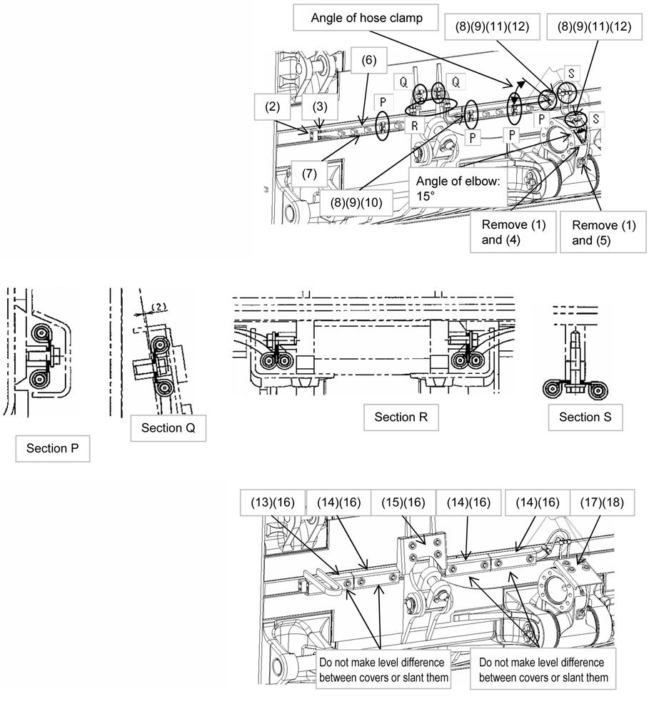
Install to carrier roller.
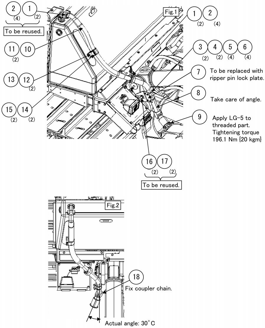
SYM.Part nameQ'ty/setRemarks 1Frame1 2Master link1HM125 3Shackle1RS10 4Shackle1RB10 5SpringR3 6Wire rope2For 5 ton 7Wire rope1For 3 ton
Sling (Pivot shaft)