6 minute read
A-9Installation of ripper

Assembly process No.
A-9 Installation of ripper (1/7)
1.Installation of beam and arm assembly
a
a
a The following is the installation procedure for the giant ripper. The installation procedure for the multi-shank ripper is basically the same as the following.
Remove all the rust-preventive oil from the ripper mounting pin and then coat the pin with new grease.
Before starting the following work, remove the lift cylinders and tilt cylinder which have been installed for transportation. Lift cylinder ass’y (1 piece) : 270 kg Tilt cylinder ass’y (1 piece) : 260 kg
1)Sling the front part with 2 chain blocks (2 t) so that slant to the right or left can be adjusted.
Weight of beam and arm : Approx. 4.2 t (Multi-shank ripper specification)
2)Since the pins at the mount are heavy, do not remove them from the mount but leave both of them inside when installing the arm. a Insert a bar between the pins and insert the pins halfway
Precautions Necessary tools Necessary equipment NameQ'tyNameQ'ty 2-t chain block 2 ø20 mm × 2 m 2 Wire rope sling ø20 mm × 3 m 1 Wire rope sling Nylon sling for 2t2
Other remarks
Assembly process No.
A-9 Installation of ripper (2/7)
3)Insert either arm pin halfway and then set the pin hole on the opposite side.
After both pins are inserted halfway, push them in to the end.
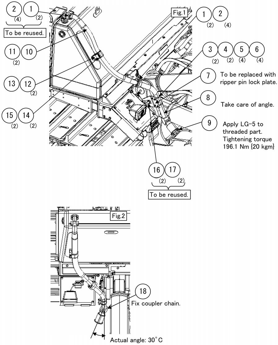
No.Part namePart No.Q'ty 1Pin195-78-711902 2Plate195-78-211712 3Bolt01010-620404 4Washer01643-320604 5Fitting07020-000002
a Installed to the machine body.
4)After inserting the pins, place wooden blocks under the center of the arm and under the beam shank holder.
Place the arm horizontally. Slant the beam a little toward the rear, considering the length of the cylinder.

Precautions Necessary tools Necessary equipment NameQ'tyNameQ'ty Wooden block 1 T 300 mm × 800 mm Wooden block 1 T 300 mm × 600 mm
Other remarks
Assembly process No.
A-9 Installation of ripper (3/7)
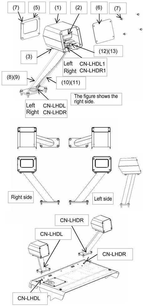
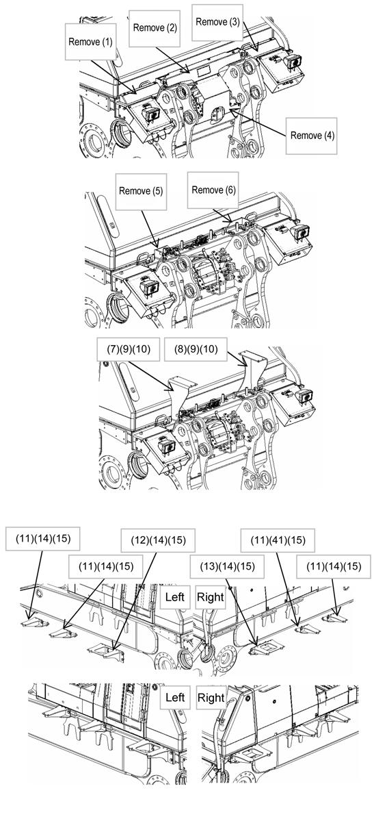
2.Installation of lift and tilt cylinders 1)Installation of lift cylinder (machine side) Sling the removed lift cylinder with crane and insert the pin (8) into the frame. (2 places on the right and left sides) Do not install lock plates at this stage. a Take care not to mistake the right and left cylinders for each other. (The directions of their pipings are different.)
No.Part namePart No.Q'ty 8Pin195-78-731702 9Fitting07020-000002
a Beam side pin is to be installed after starting the engine and operating the cylinder, following all piping works (refer to item 4).
2)Installation of tilt cylinder (machine side)
Sling the tilt cylinder with the crane and install it to the frame with pin (8), lock plate (2), bolt (3) and washer (4) (on the right and left sides). a Take care not to mistake the right and left cylinders for each other. (The directions of their pipings are different.) a Beam side pin is to be installed after starting the engine and operating the cylinder, following all piping works (refer to item 4).
No.Part namePart No.Q'ty 2Plate195-78-211712 3Bolt01010-620404 4Washer01643-320604 8Pin195-78-731702 9Fitting07070-000002
Precautions Necessary tools Necessary equipment NameQ'tyNameQ'ty Nylon sling for 2 t2 Sledge hammer (5 lb)1 Other remarks
Assembly process No.
A-9 Installation of ripper (4/7)
3.Installation of hydraulic piping
1)Install hose (6) and O-ring (7) of the lift cylinder. a When mounting cylinder, Do assembling procedure “M-4 No-injection cranking of engine” before engine start.
No.Part namePart No.Q'ty 6Hose07097-010092 7Hose07098-010A82 8O-ring07000-130328
2)Install hose (6) and O-ring (7) of the tilt cylinder.
No.Part namePart No.Q'ty 6Hose07099-010A92 7Hose07098-010A92 8O-ring07000-130328
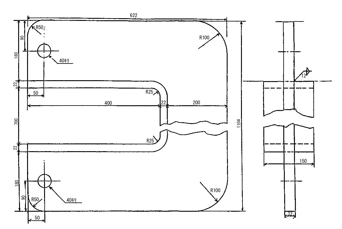
Installed angle of inside hoses of tilt cylinder

Assembly process No.
Installation of ripper (5/7)A-9
4.Bleeding air
Bleed air from the hydraulic circuit according to the following procedure. 1)Run the engine at low idle 2)Extend and retract the cylinders to above 100 mm before each stroke end 4 – 5 times. (Do not relieve the pressure at each stroke end.) 3)Extend and retract the cylinders to each stroke end 3 – 4 times. 4)While the shank point is on the ground, check that the hydraulic oil level is normal. If the hydraulic oil level is lower than the specified level, add hydraulic oil according to the Operation and
Maintenance Manual. a Lower the blade to the ground, too, at this time. 5)When bleeding air, check that each cylinder hose moves freely and oil does not leak through any joint a If the hydraulic oil level is low, the work equipment pump may be damaged. Accordingly, bleed air carefully and check the hydraulic oil level, and then add hydraulic oil if necessary.
5.Connection of tilt cylinder (on beam side) 1)Start the engine and operate the tilt cylinder as shown in the figure to adjust the cylinder length. 2)Set the pin holes and connect the tilt cylinder to the beam by pin (8), lock plate (2), bolt (3) and washer (4). (2 places on the right and left sides) a Sling the right or left cylinder first and position it properly, and then sling and position the one on the opposite side.
No.Part namePart No.Q'ty 2Plate195-78-211712 3Bolt01010-620404 4Washer01643-320604 8Pin195-78-731802 9Fitting07070-000004
6.Connection of lift cylinder (on beam side) 1)Start the engine and operate the lift cylinder as shown in the figure to adjust the cylinder length. 2)Set the pin holes and connect the lift cylinder to the beam by pin (8), lock plate (2), bolt (3) and washer (4). (2 places on the right and left sides)
No.Part namePart No.Q'ty 2Plate195-78-211712 3Bolt01010-620404 4Washer01643-320604 8Pin195-78-731802 9Fitting07070-000004 a Sling the cylinder and position it properly.
Assembly process No.
Installation of ripper (6/7)A-9
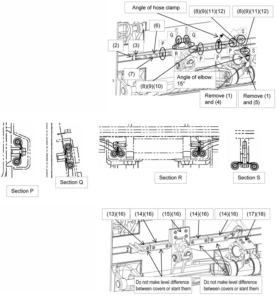
7.Piping of pin puller cylinder 1)Connect the pin puller cylinder hoses as shown in figures. a For the hose clamps, see the detailed figures. a Run the engine, operate the ripper (lifting, tilting and retraction of pin puller) and check that each hose moves freely. • Hose: 49 ± 19.6 Nm {5 ± 2 kgm}
No.Part namePart No.Q'ty Remarks 1Hose02760-003262 2Plate195-78-725711 3Sems bolt01024-812402 4Yoke144-947-28501 5Pin 04205-110281 6Pin 04050-130151 7Cushion07095-003146Machine without ripper point light uses only four. 8Clamp07094-303156Machine without ripper point light uses only four. 9Sems bolt01024-810653Machine without ripper point light uses only four.
Assembly process No.
Installation of ripper (7/7)A-9
8.Confirm whether the ripper cylinder hose and pin puller hose do not interfere other parts by operating the ripper to raise/lower, to tilt-in/tilt-back.
If there is any interference, adjust the hose position by loosening the mouthpiece flange of hose. (cylinder hose)
Adjust the clamp position so that pin puller hose does not interfere others or stretch too tight.
9.Installation of shank assembly (for giant ripper) a Perform this work after installing the tracks since the machine is required to ride over something in reverse.
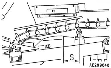
1)Install a wire to the hook at the top of the shank assembly, put it up through the holder, sling it with crane, and adjust the ripper to match the shank hole with the holder hole as shown in the right figure.
2)Insert the pin in the shank by operating the pin puller cylinder.
a Do not move the holder and shank simultaneously.
No.Part namePart No.Q'ty 1Shank195-79-511501 2Pin195-78-713601 3Protector195-78-711111 4Pin195-78-713602
10.Installation of shank assembly (for multi-shank ripper)
1)Install a wire to the hook at the top of the shank assembly, pass it up through the holder, pull it up with the crane and set the shank hole to the holder hole.
2)Insert the shank fixing pin and lock it by hitting the lock pin with a hammer.
No.Part namePart No.Q'ty 1Shank195-78-713103 2Pin195-78-713603 3Protector195-78-711113 4Pin195-78-713606