1 minute read
A-14Installation of grease hose of blade joint (if equipped

Assembly process No.
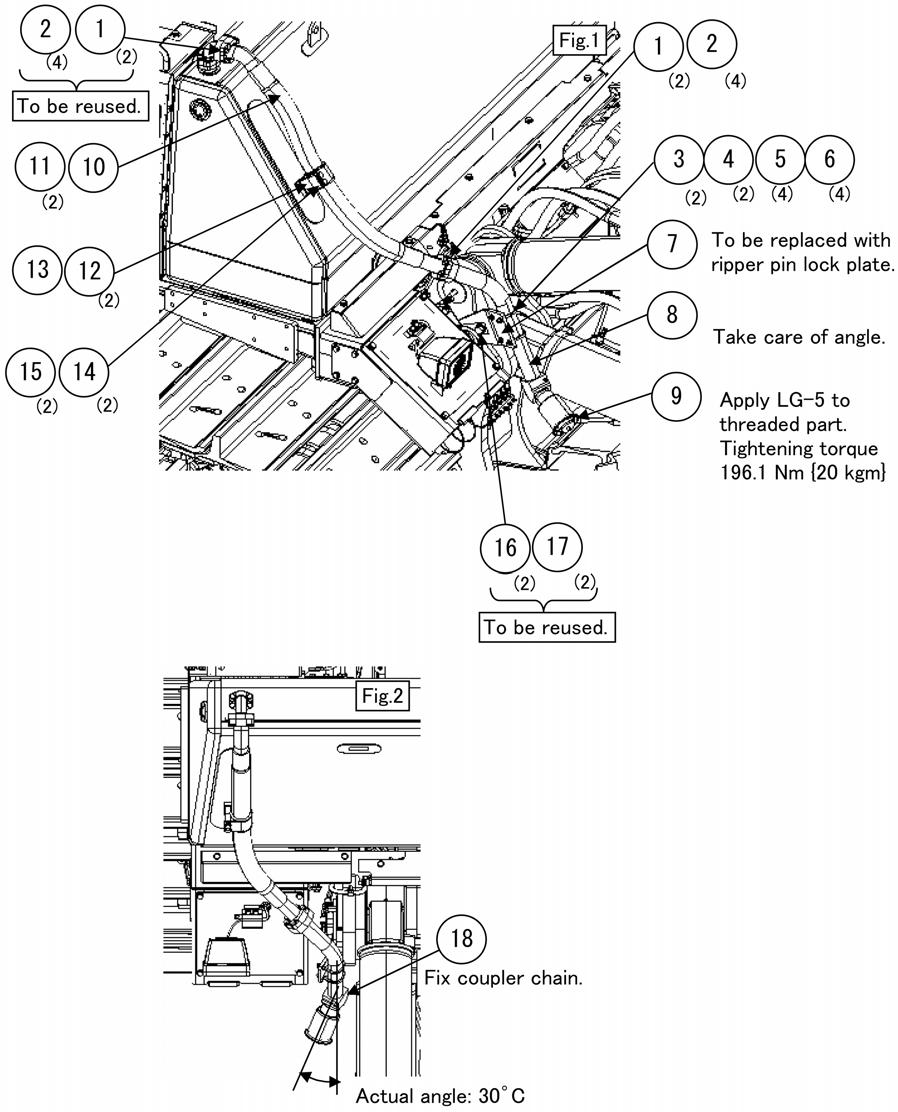
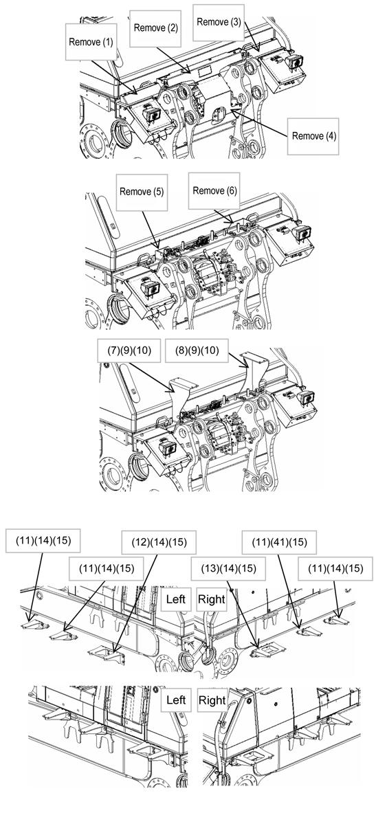
1.Installation of grease piping of blade
(1)Remove nipple (1) installed to the center link.
(2)Install nipples (2) and (3) to the bosses at the left back of the blade.
(3)Install elbow (3) and nipple (4) to the center link.
(4)Install hoses (5) and (6) by using clamps (7), (8), (9), (10), (11), and (12).
(5)Connect hoses (6) and (7) to nipple (3), elbow (4), and nipple (5).
2.Installation of hose covers
(1)Install covers (13), (14), and (15) by using bolts (16).
(2)Install cover (17) by using bolts (18).
When installing covers (13) and (14), do not make a level difference or slant them.
No.Part namePart No. Q’ty RemarksNo.Part namePart No. Q’ty 1 Nipple07020-000002For transportation10Bolt01024-812306 2Nipple07020-000002 11Bolt01024-812502 3Nipple203-62-217402 12Spacer195-33-112202 4Elbow198-68-11341113Cover195-68-116211 5Nipple198-68-11640114Cover195-68-116313 6Hose198-68-1182013,100 mm15Cover195-68-116611 7Hose195-68-1224012,900 mm16Bolt01024-8123012 8Clamp04434-517122017Cover195-68-111601 9Bushing07095-202112018Bolt01024-812804 Remarks
Assembly process No.
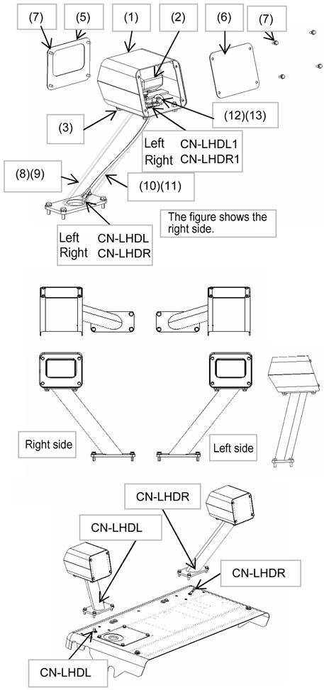
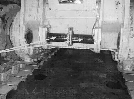
3.Installation of grease piping of straight frame (Perform on both right and left sides)
(1)Remove nipple (1) installed to the straight frame and install elbow (2).
(2)Install nipples (3) and (4) to the bosses on the straight frame.
(3)Connect hose (5) to elbow (2) and nipple (4).
(4)Install hose (5) by using clamps (6), (7), and (8).
4.Installation of hose covers

(1)Install covers (9) and (10) by using bolts (11) and (12).
No.Part namePart No. Q’ty Remarks 1 Nipple07020-000002For transportation 2Elbow198-68-119212 3Nipple07020-000002 4Nipple203-62-217402 5Hose195-68-115101420 mm 6Clamp04434-517122 7Bushing07095-202112 8Bolt01024-812302 9Cover (LH)195-68-113401 10Cover (RH)195-68-113501 11Bolt01010-820404 12Washer01643-320604