9 minute read
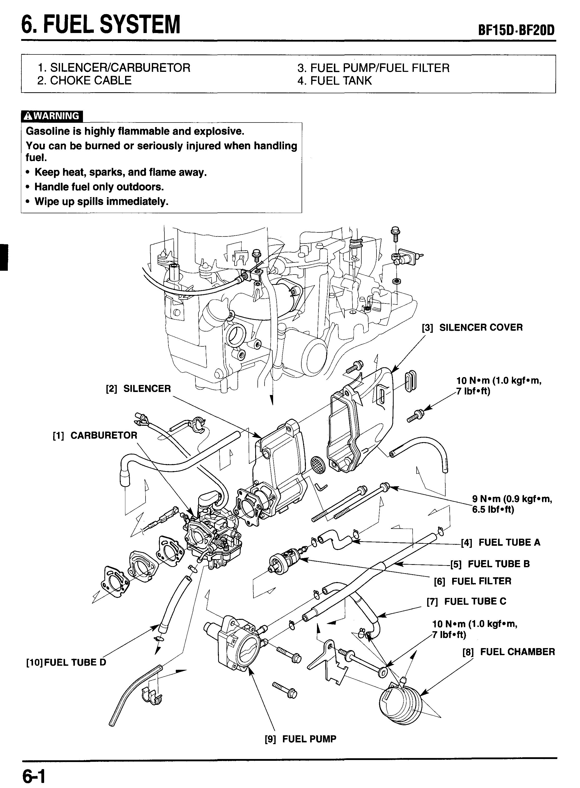
6. FUEL SYSTEM


Gasoline is highly flammable and explosive. You can be burned or seriously injured when handling fuel.
Keep heat, sparks, and flame away.
Handle fuel only outdoors.
Wipe up spills immediately.
1. SILENCEWCARBURETOR
a. REMOVAL
Before removal, drain the gasoline to a suitable container from the carburetor by loosening the drain screw.
Gasoline is highly flammable and explosive. You can be burned or seriously injured when handling fuel.
Keep heat, sparks, and flame away.
Handle fuel only outdoors.
Wipe up spills immediately.
1) Remove the engine cover and right engine under cover
(P. 5-3).
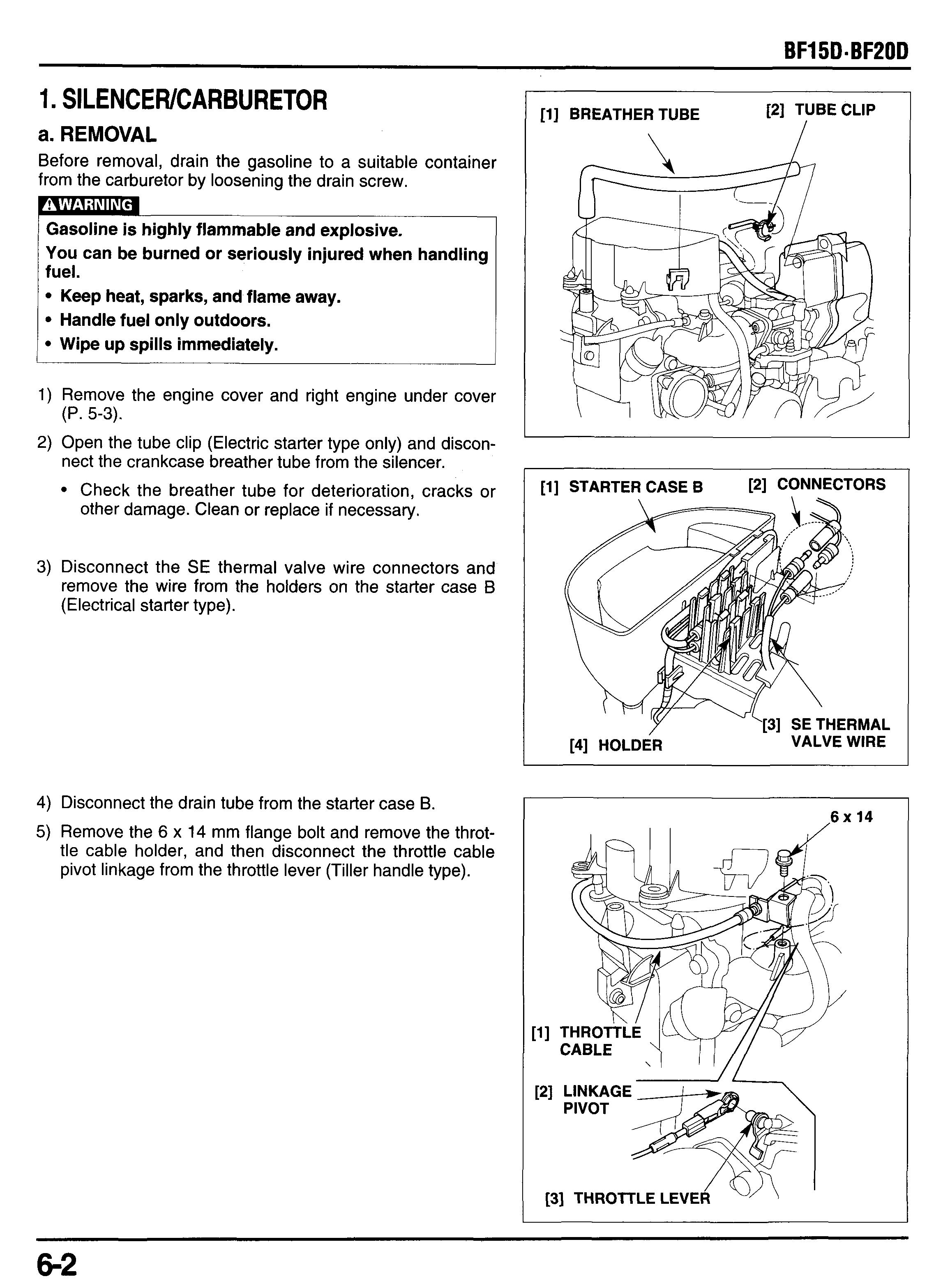
2) Open the tube clip (Electric starter type only) and disconnect the crankcase breather tube from the silencer. Check the breather tube for deterioration, cracks or other damage. Clean or replace if necessary.
3) Disconnect the SE thermal valve wire connectors and remove the wire from the holders on the starter case B (Electrical starter type).
4) Disconnect the drain tube from the starter case B.
5) Remove the 6 x 14 mm flange bolt and remove the throttle cable holder, and then disconnect the throttle cable pivot linkage from the throttle lever (Tiller handle type).
6) Loosen the throttle rod lock bolt and disconnect the linkage pivot from the carburetor throttle lever (Remote control type).
7) Remove the two 6 x 22 mm flange bolts and silencer cover.
8) Remove the fuel tube B from the hook of the silencer.
9) Disconnect the fuel tube D from the carburetor.
10)Remove the tube clamp.
11)Remove the two 6 x 106 mm flange bolts, silencer, carburetor, gasket and carburetor insulators.
Replace the carburetor gasket and insulator gaskets with new ones when disassembly. Do not reuse.
12)Loosen the valve nut and remove the manual SE valve (Type without electric starter).
b. CARBURETOR DISASSEMBLY
Before disassembly, completely drain the carburetor by loosening the drain screw. Clean the outside of the carburetor before disassembly.
Gasoline is highly flammable and explosive. You can be burned or seriously injured when handling fuel.
Keep heat, sparks, and flame away.
Handle fuel only outdoors.
Wipe up spills immediately.
1) Remove the screw and set plate, then remove the auto SE thermal valve and O-ring (Type with electric starter).
2) Remove the drain tube from the float chamber.
3) Remove the four washer screws and remove the float chamber and O-ring.
4) Remove the set screw and remove the accelerator piston and spring.
5) Remove the set screw, then pull out the float pin and remove the float and float valve.
6) Remove the main jet with care not to damage the main
7) Remove the plug screw, main nozzle and jet nozzle takjet. ing care not to damage them.
21 MAIN NOZZLE
c. CLEANING
piGTiCF
Some commercially available chemical cleaners are caustic. These cleaner may damage plastic parts such as 0rings, float and float valve. Check the container for instructions. If you are in doubt, do not use these products to clean carburetor.
. High air pressure may damage the carburetor. Use low pressure setting when cleaning the passages and parts.
1) Clean the carburetor body, removed parts and float chamber with cleaning solvent.
2) Use low air pressure and blow off the removed jets, nozzles and passages of the carburetor body and float chamber.
d. INSPECTION
Float Level Height
Place the carburetor in the position as shown and measure the distance between the float top and carburetor body when the float just contacts the seat without compressing the valve spring.
1 Standard float height 13.7 mm (0.54 in) I
If the height is out of specification, adjust the float height by bending the float mounting tab carefully.
FLOAT /FLOAT VALVEFLOAT VALVE SEAT
1) Check the float for crack or damage. Replace if neces-
2) Check the float valve for wear or damage, replace if necsary. essary.
NOULES/JETS
Check the main jet, main nozzle jet nozzle for clogged or damage. Replace if necessary.
Se Thermal Valve
1) Check the valve piston and needle for wear or scratch. replace as assembly, if necessary.
2) Measure the resistance between the terminals e. PILOT SCREW
This test can be made with the carburetor installed on the motor.
3) Install a vinyl tube as shown.
4) At room temperature, make sure that breath should be passed through passage.
5) Connect the 12V battery positive terminal to the Brown/white terminal and negative to BlacWgreen terminal for about five minutes. Then check that breath should not be passed through.
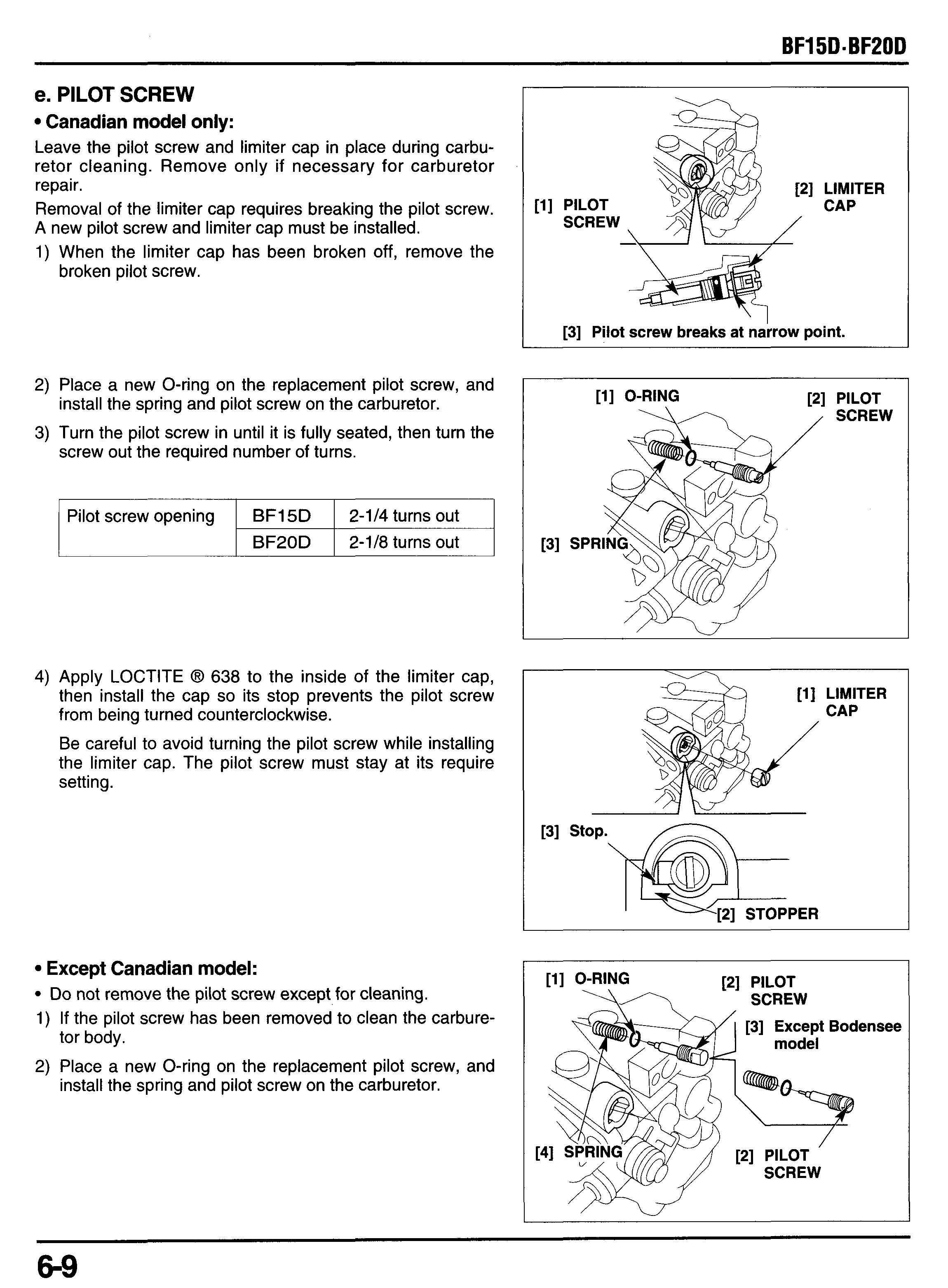
Canadian model only:
Leave the pilot screw and limiter cap in place during carburetor cleaning. Remove only if necessary for carburetor repair.
Removal of the limiter cap requires breaking the pilot screw. A new pilot screw and limiter cap must be installed.
1) When the limiter cap has been broken off, remove the broken pilot screw.
PILOT
I [3] Pilot screw breaks at narrow point.
2) Place a new O-ring on the replacement pilot screw, and
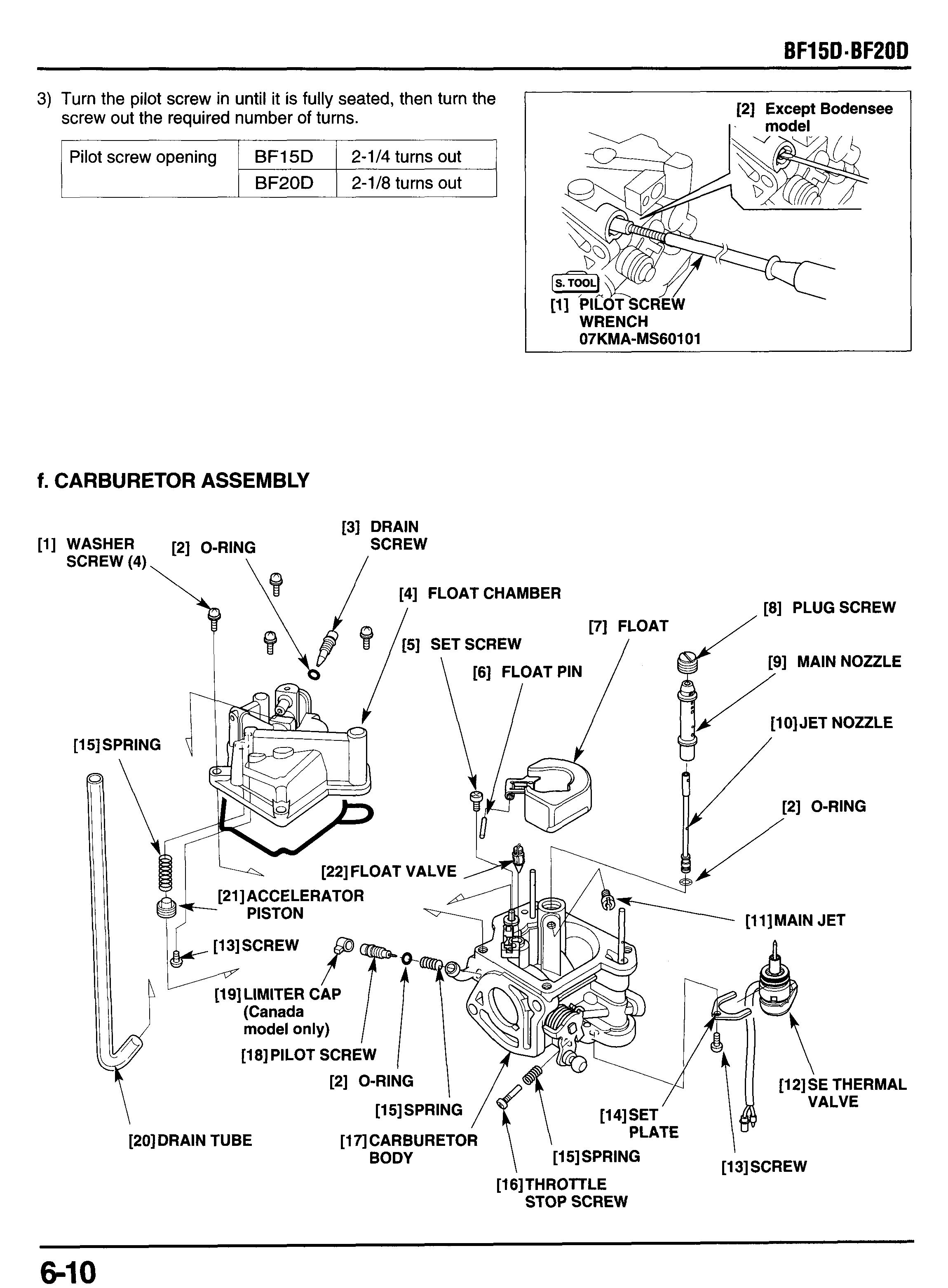
3) Turn the pilot screw in until it is fully seated, then turn the install the spring and pilot screw on the carburetor. screw out the required number of turns.
Pilot screw opening
BF15D 2-114 turns out BF20D 2-1/8 turns out
4) Apply LOCTITE @ 638 to the inside of the limiter cap, then install the cap so its stop prevents the pilot screw from being turned counterclockwise.
Be careful to avoid turning the pilot screw while installing the limiter cap. The pilot screw must stay at its require setting.
Except Canadian model:
Do not remove the pilot screw except for cleaning.
1) If the pilot screw has been removed to clean the carbure-
2) Place a new O-ring on the replacement pilot screw, and tor body. install the spring and pilot screw on the carburetor.
[l]
3) Turn the pilot screw in until it is fully seated, then turn the screw out the required number of turns.
1 Pilot screw opening BF15D 1 2-1/4 turns out I
I I BF20D I 2-1/8 turnsout I
1) Install a new O-ring to the jet nozzle.
2) Install the jet nozzle, main nozzle and secure them with the plug screw.
3) Install the main jet. Take care not damage the jet and nozzle when handling them.
4) Install the float valve to the float tab as shown.
5) Insert the float pin to the float and set them onto the carburetor body and secure them with the set screw.
6) Install the spring and accelerator piston and secure the piston with the set screw.
7) Install a new O-ring to the drain screw and install the
8) Install a new O-ring (float chamber seal) onto the float drain screw to the float chamber. chamber.
[l] FLOAT CHAMBER [2] FLOAT SEAL CHAMBER
9) Install the float chamber to the carburetor body and tighten the four washer screws securely.
[l] WASHER SCREW(4)
10)lnstall the throttle stop screw and spring.
1l)lnstall a new O-ring to the SE thermal valve and install the SE thermal valve with the setting plate and loosely install the setting screw.
12)Set the SE thermal valve as shown noting the direction and tighten the set screw securely.
[2] SCREW [31 SET VALVE
[q SPRING 141 THROTTLE STOP
[l] SE THERMAL SCREW VALVE \
TORQUE:
2) Install the carburetor, silencer, carburetor insulator, new carburetor gaskets and a silencer gasket. Align the cutouts of the carburetor insulator and carburetor gaskets.
3) Tighten the two 6 x 106 mm flange bolt to the specified torque.
TORQUE: 9 N m (0.9 kgf m, 7 Ibfoft)
6) Clump the fuel tube to the hook of the silencer cover.
7) Install the seal rubber to the silencer cover as shown. Install the silencer cover to the silencer and tighten the 6 x 22 mm flange bolts to the specified torque.
TORQUE: 9 N*m (0.9 kgf om, 7 Ibf eft) shown.
8) Insert the tube end to the recess on the oil case as
9) Connect the linkage pivot to the carburetor throttle lever.
10)lnstall the throttle cable stay with the 6 x 14 mm flange bolt (Tiller handle type). After installation, adjust the throttle linkage (P. 3-13).
11)Connect the tube to the tube join of the starter case B, and set the starter case B securely by setting the grommets to the bosses of the cylinder head cover.
12)Connect the throttle control cable to the throttle arm (Remote control type). After installation, adjust the throttle linkage (P. 3-14).
13)Connect the SE thermal valve wire connectors and secure the wires with the clamp on the starter case B (Electric starter type).
14)lnstall the breather tube between the silencer and cylin- der head cover. type). engine cover.
15)Clump the tube with the 13 mm tube clip (electric starter
2. CHOKE CABLE (Type Without electric starter type)
Take care to prevent foreign material from entering the carburetor.
a. DISASSEMBLY
1) Remove the engine cover and right engine under cover
2) Remove the recoil starter (P. 7-2).
3) Loosen the valve nut, then disconnect the SE valve from
(P. 5-2). the carburetor

4) Remove the SE valve and spring.
5) Loosen the cable nut and remove the choke cable from the oil case.
b. INSPECTION
Check the distance from the end of the valve nut to the stopped surface of the SE valve. It should be 14 mm (0.6 in).
c. REASSEMBLY
1) Completely loosen the cable holder nut and install the choke cable onto the oil case. nut.
2) Secure the choke cable by tightening the cable holder
3) Install the spring and SE valve.
4) Route the choke cable as shown below.
5) Install the SE valve to the carburetor and loosely tighten the valve nut. Adjust the cable direction as shown and tighten the valve nut securely.
3. FUEL PUMPlFUEL FILTER
a. REMOVAL
Gasoline is highly flammable and explosive. You can be burned or seriously injured when handling fuel.
Keep heat, sparks, and flame away. Handle fuel only outdoors. Wipe up spills immediately.
1) Remove the engine cover and right engine under cover (P.5-2).
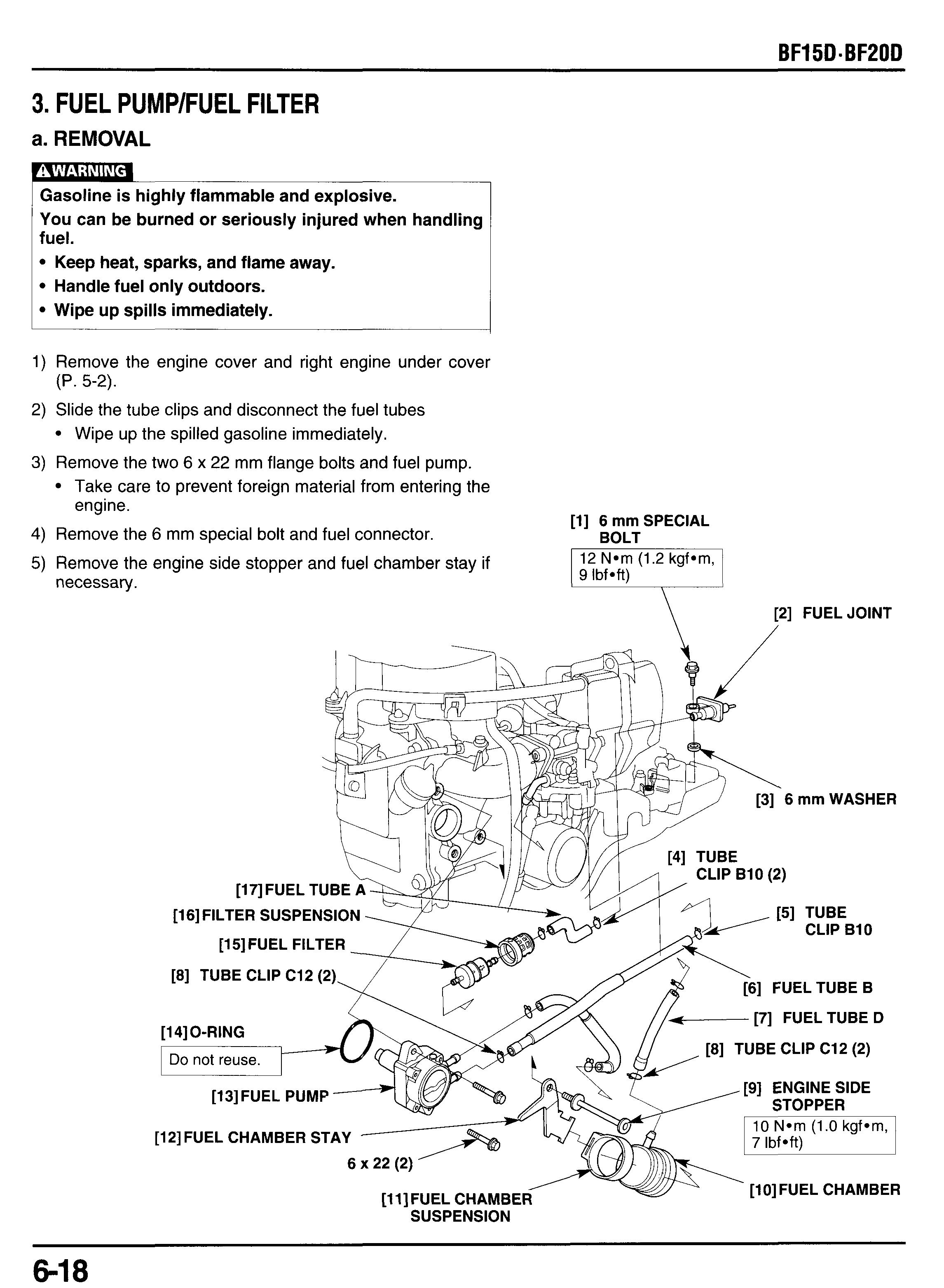
2) Slide the tube clips and disconnect the fuel tubes Wipe up the spilled gasoline immediately.
3) Remove the two 6 x 22 mm flange bolts and fuel pump. Take care to prevent foreign material from entering the engine.
4) Remove the 6 mm special bolt and fuel connector.
5) Remove the engine side stopper and fuel chamber stay if necessary.
b. INSPECTION
FUEL PUMP
Gasoline is highly flammable and explosive. You can be burned or seriously injured when handling fuel.
Keep heat, sparks, and flame away. Handle fuel only outdoors. Wipe up spills immediately.
I) Remove the spark plugs from the No. 1 and 2 cylinder.
2) Connect the fuel tube from the fuel tank to the fuel con- nector.
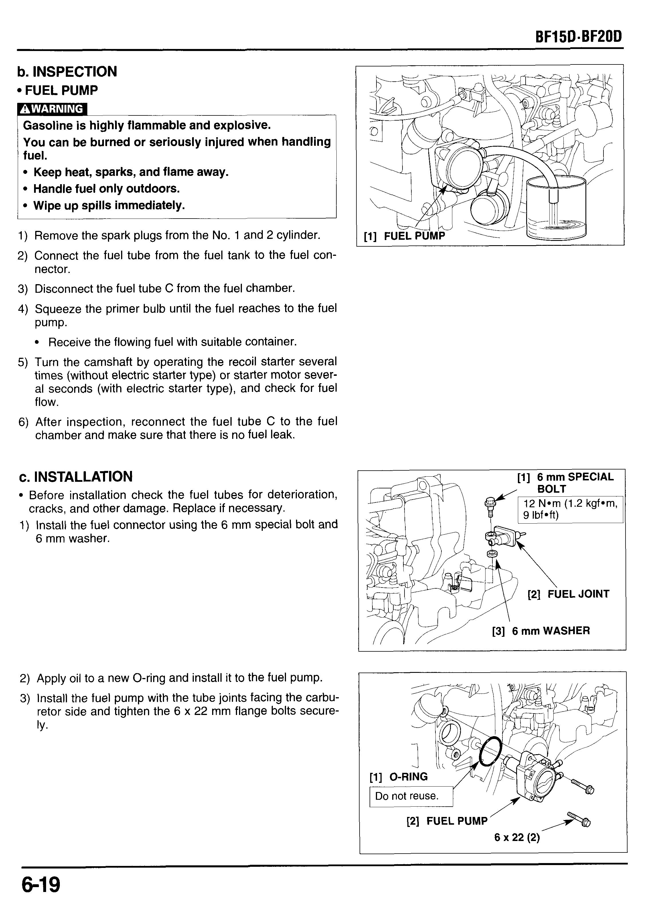
3) Disconnect the fuel tube C from the fuel chamber.
4) Squeeze the primer bulb until the fuel reaches to the fuel pump.
Receive the flowing fuel with suitable container.
5) Turn the camshaft by operating the recoil starter several times (without electric starter type) or starter motor several seconds (with electric starter type), and check for fuel flow.
6) After inspection, reconnect the fuel tube C to the fuel chamber and make sure that there is no fuel leak.
c. INSTALLATION
Before installation check the fuel tubes for deterioration,
1) Install the fuel connector using the 6 mm special bolt and cracks, and other damage. Replace if necessary. 6 mm washer.
2) Apply oil to a new O-ring and install it I the fuel pump.
3) Install the fuel pump with the tube joints facing the carburetor side and tighten the 6 x 22 mm flange bolts securely.
4) Connect the fuel tube C and D to the fuel chamber as shown and secure them with the tube clips. Connect the fuel tube C to the fuet chamber with the big side toward fuel chamber side.
5) Install the fuel chamber stay with the stopper contact to the fuel pump mounting boss as shown, and tighten the engine side stopper to the specified torque.
TORQUE: 10 Nom (1.0 kgfom, 7 Ibfoft)
[4] ENGINE SIDE STOPPER
10 N*m (1.0 kgf*m, 7 Ibf*ft)
[6] STOPPER
6) Connect the fuel tube B to the lower joint (4 mark) and fuel tube C to the upper joint ( b mark).
7) Install the fuel filter into the filter suspension so the arrow mark points same direction as shown. Install them so the arrow mark on the filter suspension points toward the fuel pump side.
8) After installation, connect the fuel hose connector to the outboard motor. Pump the primer bulb, and make sure that there is no fuel leaks.
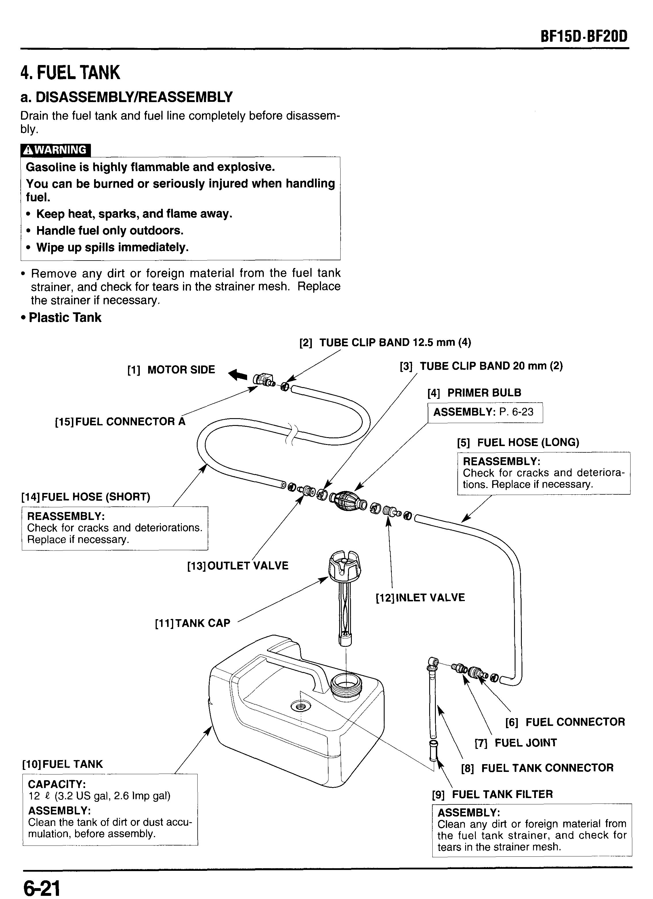
4. FUEL TANK
a. DISASSEMBLY/REASSEMBLY flammable and explosive. You can be burned or seriously injured when handling fuel.
Drain the fuel tank and fuel line completely before disassembly.
Keep heat, sparks, and flame away.
Handle fuel only outdoors.
Wipe up spills immediately.
Remove any dirt or foreign material from the fuel tank strainer, and check for tears in the strainer mesh. Replace the strainer if necessary.
Plastic Tank
[l]MOTOR SIDE
[15] FUEL CONNECTOR A
[14] FUEL HOSE (SHORT)
REASSEMBLY:
‘Check for cracks and dete 1 Replace if necessary.
[2] TUBE CLIP BAND 12.5 mm (4) /
[3] TUBE CLIP BAND 20 mm (2)
[4] PRIMER BULB
ASSEMBLY: P. 6-23
[5] FUEL HOSE (LONG)
[12]lNLET VALVE
[lO]FUEL TANK
CAPACITY:
12 J? (3.2 US gal, 2.6 Imp gal)
ASSEMBLY:
Clean the tank of dirt or dust accumulation, before assembly.
[6] FUEL CONNECTOR
[7] FUEL JOINT
[8] FUEL TANK CONNECTOR
[9] FUEL TANK FILTER
ASSEMBLY:
Clean any dirt or foreign material from the fuel tank strainer, and check for tears in the strainer mesh.


