13 minute read
4. PROPELLEWGEAR CASUEXTENSION CASE


1. PROPELLER
2. PROPELLER SHAFT
3.
4.
5.
6. WATER PUMP HOUSING
7. GEAR CASEIANODENVATER SCREEN
8. EXTENSION CASE
9.
1. PROPELLER
a. REMOVAL
1) Remove the 3 mm cotter pin and discard it.
2) Remove the 10 mm castle nut and washer.
3) Remove the propeller and thrust washer.
b. INSTALLATION
1) Apply marine grease to the spline and thread sections of the propeller shaft.
2) Install the thrust washer with the flange section toward the gear case.
3) Install the propeller and 10 mm washer onto the propeller shaft.
4) Tighten the 10 mm castle nut to the specified torque.
TORQUE: 1 N-m (0.1 kgf-m,0.7 Ibf-ft)
5) If the cotter pin cannot be set, tighten the nut additionally until the cotter pin can be set.
Do not overtighten exceeding the maximum torque.
MAX. TORQUE: 35 N*m (3.5kgf*m,25 Ibfoft)
6) Install a new cotter pin and bend the pin ends as shown to stake the castle nut as shown.
Be sure to use the genuine honda part (stainless steel made) or equivalent.
2. PROPELLER SHAFT HOLDER
a. REMOVAL
1) Remove the propeller (P. 4-2).
2) Set the gear in the neutral position and remove the two 6 x 20 mm flange bolts.
3) Using a screw drivers and remove the propeller shaft holder assembly with care not to damage the gear case.
b. DISASSEMBLY
1) Remove the shift slider.
2) Remove the propeller shaft assembly, reverse bevel gear and thrust washer from the propeller shaft holder.
[l]
12] CUTyT \ I 6x20 (2)
3) Remove the cross pin ring from the clutch shifter.
[5] PROPELLER SHAFT ASSY.
[l] CROSS PIN RING \ PI
CLUTCH SHIFTER
4) Drive out the 4 x 30 m shifter pin using a commercially available 4 mm pin driver.
[l] 4 mm PIN DRIVER (commercially available)
[2] 4x30mm SHIFTER PIN
5) Remove the shift spring and clutch shifter from the propeller shaft.
c. INSPECTION
CLUTCH SHIFTER
Check the clutch dogs for wear or damage.
Propeller Shaft
Measure the O.D. of the propeller shaft at the forward bevel gear area.
Reverse Bevel Gear
Check the clutch dogs and gear teeth for wear or damage. Replace as an assembly with the propeller shaft if necessary.
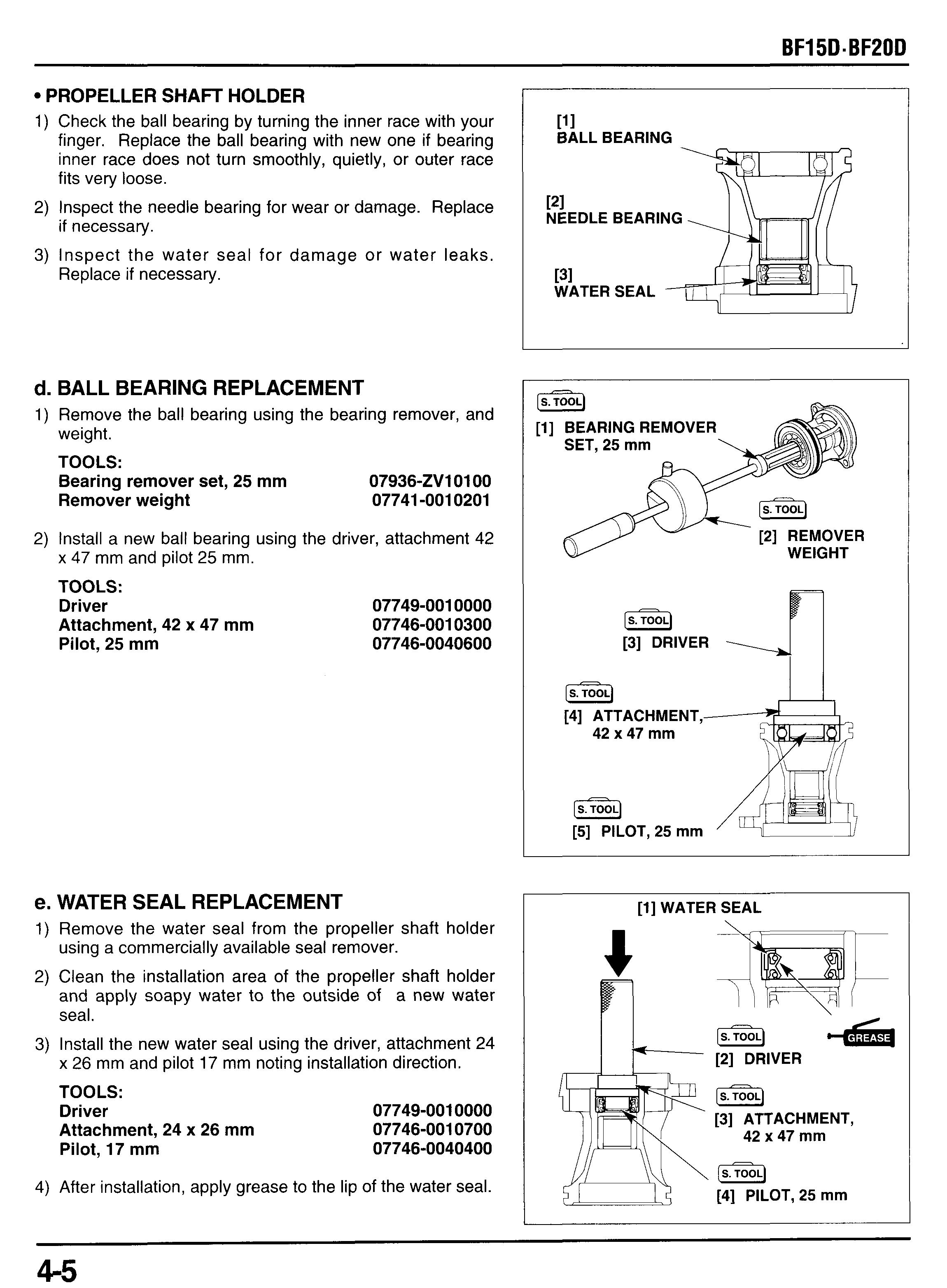
Propeller Shaft Holder
1) Check the ball bearing by turning the inner race with your finger. Replace the ball bearing with new one if bearing inner race does not turn smoothly, quietly, or outer race fits very loose.
2) Inspect the needle bearing for wear or damage. Replace if necessary.
3) Inspect the water seal for damage or water leaks. Replace if necessary.
d. BALL BEARING REPLACEMENT
1) Remove the ball bearing using the bearing remover, and weight.
TOOLS: Bearing remover set, 25 mm
2) Install a new ball bearing using the driver, attachment 42 x 47 mm and pilot 25 mm.
TOOLS:
Driver 07749-0010000
Attachment, 42 x 47 mm 07746-0010300 Pilot, 25 mm 07746-0040600
e. WATER SEAL REPLACEMENT
1) Remove the water seal from the propeller shaft holder using a commercially available seal remover.
2) Clean the installation area of the propeller shaft holder and apply soapy water to the outside of a new water seal.
3) Install the new water seal using the driver, attachment 24 x 26 mm and pilot 17 mm noting installation direction.
TOOLS: Driver 07749-0010000
Attachment, 24 x 26 mm 07746-0010700
17 mm 07746-0040400
4) After installation, apply grease to the lip of the water seal.
f. NEEDLE BEARING REPLACEMENT
1) Remove the water seal from the propeller shaft holder
2) Remove the needle bearing using the driver, attachment using a commercially available seal remover. 24 x 26 mm and pilot 17 mm
TOOLS:
Driver
Attachment, 24 x 26 mm
Pilot, 17 mm
07749-0010000
07746-0010700
07746-0040400
3) Press in a new needle bearing with the driver 14.5 x 18.5 mm and pilot 17 mm using the hydraulic press.
Set the pilot 17 mm to the larger diameter side of the attachment as shown.
TOOLS:
Driver, 14.5 x 18.5 mm
Pilot, 17 mm
4) Install a new water seal (P. 4-5).
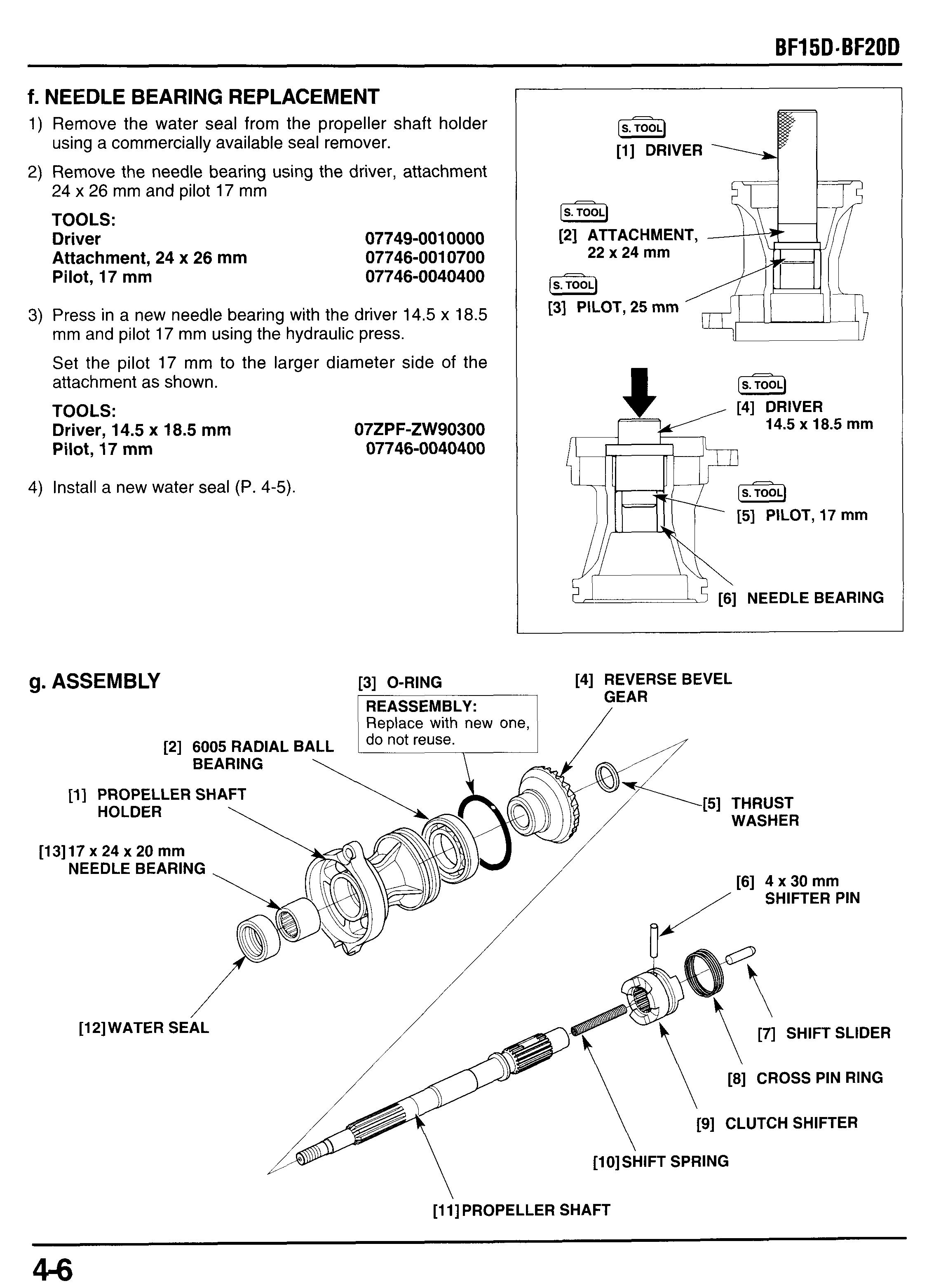
07ZPF-ZW90300
07746-0040400
[2] ATTACHMENT, 22 x 24 mm
[3] PILOT, 25 mm x 18.5 mm
1) Install the clutch shifter with the "F" mark facing toward the forward bevel gear side and align the center of the clutch shifter pin hole with the shifter pin groove of the propeller shaft as shown.
2) Install the shift spring into the propeller shaft
3) Push the shift spring with a screw driver and install the 4 x 30 mm shifter pin.
4) Install the cross pin ring.
5) Apply marine grease to a new O-ring and install it to the
6) Install the reverse bevel gear to the ball bearing inner propeller shaft holder. race of the propeller shaft holder.
7) Apply marine grease to the water seal lips.
8) Install the thrust washer onto the propeller shaft, then install them into the propeller shaft holder.
9) Install the shift slider.
h. INSTALLATION
1) Apply marine grease to the O-ring and mating surfaces of the propeller shaft holder and gear case.
2) Install the propeller shaft assembly to the gear case and tighten the two 6 x 20 mm flange bolts to the specified torque.
TORQUE: 12 N*m (1.2 kgf*m, 9 Ibf*ft)
3) After reassembly, add the gear mended oil (P. 3-6). case
3. GEAR CASE ASSEMBLY
a. REMOVAL
1) Shift the gear into the R "reverse" position.
2) Loosen the lock nut and disconnect the shift rod B from the shift rod A by turning the adjusting nut.
3) Tilt up the motor.
4) Remove the 6 mm flange bolts.
SHIFT ROD
INSTALLATlON
Install the two 6 x 10 mm dowel pins on the gear case. Apply marine grease to the following position:
- spline of the vertical shaft.
- inside of the water tube seal.
Install the gear case assembly by aligning the vertical shaft spline with the crankshaft, and water tube with the water tube seal.
Loosely install the 6 mm flange bolts or 6 mm self-locking nuts.
Tighten the 6 mm flange bolts or 6 mm self-locking nuts in a crisscross patter in 2-3 steps to the specified torque.
TORQUE: 12 N*m (1.2 kgfam, 9 Ibf*ft)
6) Make sure that the gear shift in the "R" (reverse) position.
7) Turn the lock nut on the shift rod B to obtain 8 mm (0.3 in) from top of the shift rod B to top of the lock nut as shown.
8) Make sure that the shift rod is in reverse position and connect the shift rod B to the shift rod A by threading the adjusting nut until the adjusting nut comes in contact with the lock nut.
9) When the adjusting nut contacts the lock nut, tighten the lock nut by holding the adjusting nut.
TORQUE: 10 N*m (1.0 kgf*m, 7 Ibfoft)
1O)After adjustment, be sure that the gearshift lever or remote control lever moves smoothly into all position.
11)After reassembly, add the gear case with the recommended oil (P. 3-6).
4. WATER PUMP
a. DISASSEMBLY
1) Remove the following:
-the propeller (P. 4-2).
-the propeller shaft holder (P. 4-3).
2) Remove the water tube seal ring and water pump hous-
3) Remove the four 6 mm washer bolts and impeller hous-
- the gear case assembly (P. 4-9). ing grommet. ing.
4) Remove the key from the vertical shaft.
5) Remove the O-ring., pump impeller and impeller liner from the impeller housing.
6) Remove the impeller cover
7) Remove the gasket. Replace the gasket with new one when the gasket is removed.
b. INSPECTION
PUMP IMPELLER
Check the pump impeller for wear, damage or cracks, replace if necessary.
6x50mm WASH
[2] WATER TUBE SEAL N*m (1
[3] IMPELLER HOUSING ~_____
[4] IMPELLER COVER
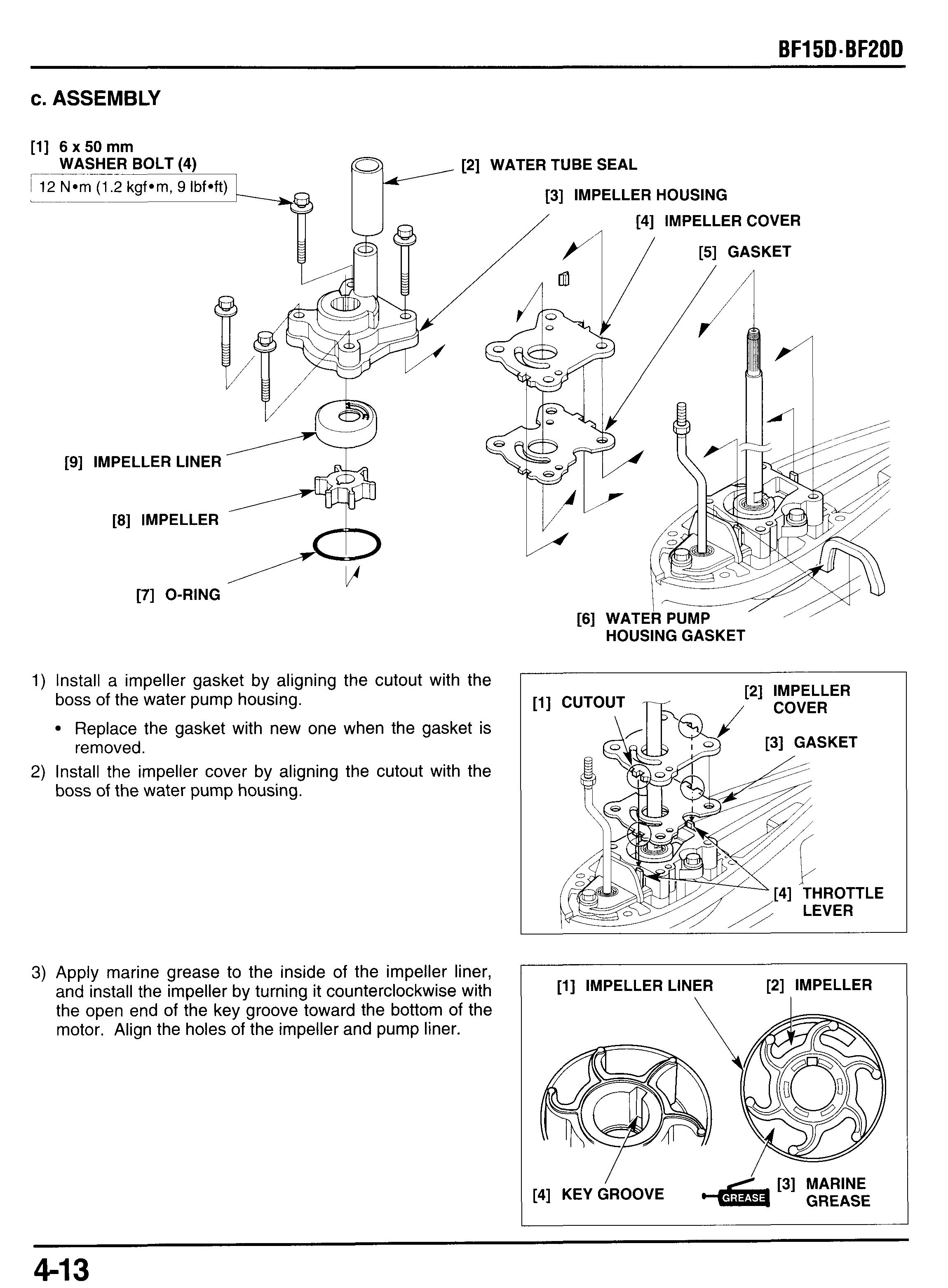
1) Install a impeller gasket by aligning the cutout with the boss of the water pump housing. Replace the gasket with new one when the gasket is removed.
2) Install the impeller cover by aligning the cutout with the boss of the water pump housing.
3) Apply marine grease to the inside of the impeller liner, and install the impeller by turning it counterclockwise with the open end of the key groove toward the bottom of the motor. Align the holes of the impeller and pump liner.
[l]IMPELLERLINER [2] IMPELLER
4) Apply thin coat of grease to the outside of the liner to hold them in the impeller housing, install the pump liner and impeller as an assembly by aligning the tabs of the liner with the groove of the impeller housing.
5) Apply marine grease to a new O-ring and install it to the impeller housing.
6) Apply thin coat of grease to the key setting groove of the vertical shaft and set the key.
[l]
[2]
6x50mm
WASHER
TORQUE: 11 N*m (1.1 kgf m, 8 Ibf ft)
9) Apply marin grease to th inside of the water tub- seal ring and installit to the impeller housing. Install the water pump housing grommet.
10)lnstall the following:
- gear case assembly (P. 4-10 and 11)
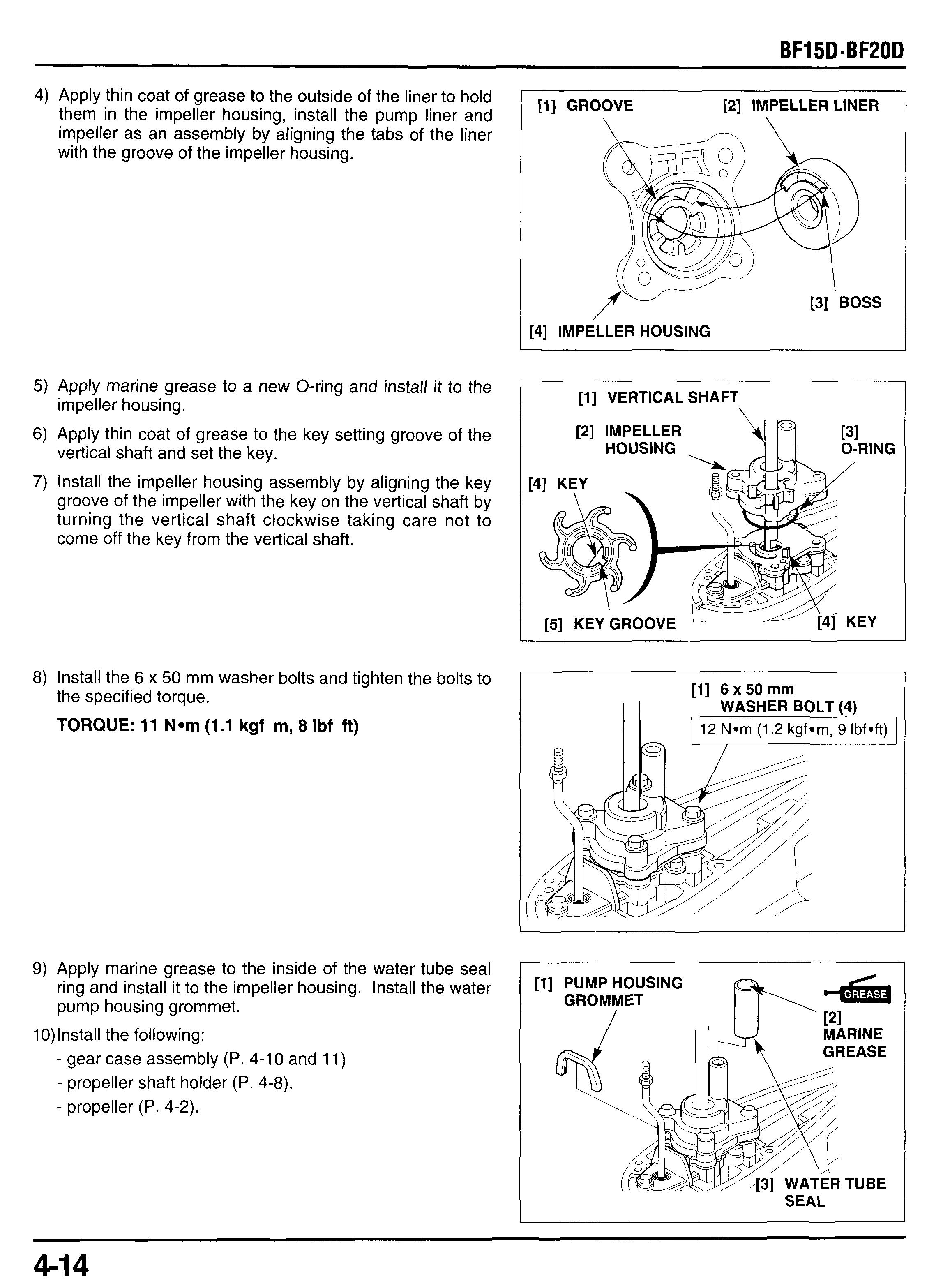
- propeller shaft holder (P. 4-8).
[l]
5. VERTICAL SHAFTBEVEL GEAR
a. DISASSEMBLY
1) Remove the following:
- propeller (P4-2)
- propeller shaft holder (P. 4-3).
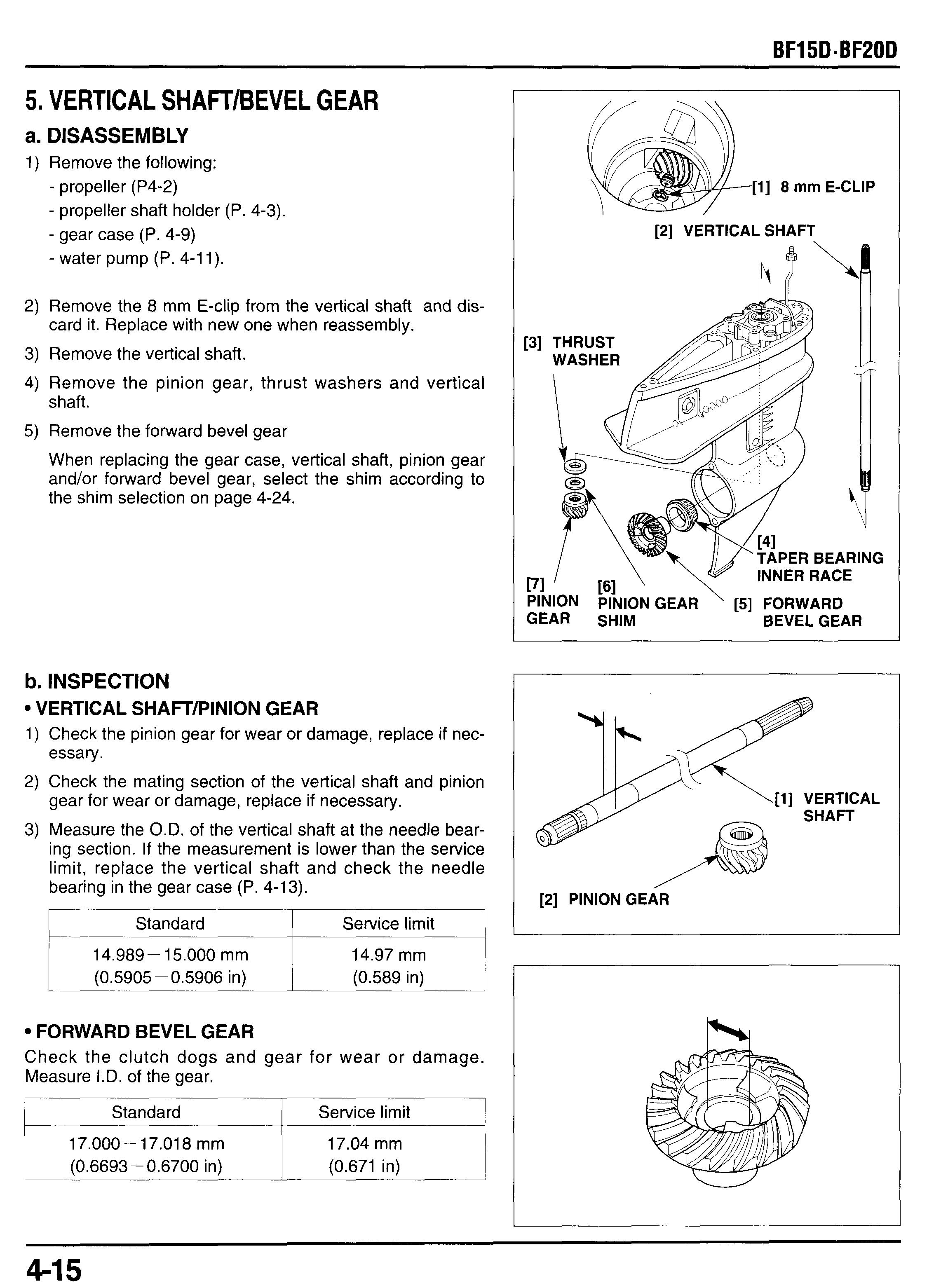
- gear case (P. 4-9)
- water pump (P. 4-1 1).
2) Remove the 8 mm E-clip from the vertical shaft and dis-
3) Remove the vertical shaft.
4) Remove the pinion gear, thrust washers and vertical card it. Replace with new one when reassembly. shaft.
5) Remove the forward bevel gear
When replacing the gear case, vertical shaft, pinion gear and/or forward bevel gear, select the shim according to the shim selection on page 4-24.
b. INSPECTION
Vertical Shafvpinion Gear
1) Check the pinion gear for wear or damage, replace if necessary.
2) Check the mating section of the vertical shaft and pinion gear for wear or damage, replace if necessary.
3) Measure the O.D. of the vertical shaft at the needle bearing section. If the measurement is lower than the service limit, replace the vertical shaft and check the needle bearing in the gear case (P. 4-13).
* FORWARD BEVEL GEAR
Check the clutch dogs and gear for wear or damage. Measure I.D. of the gear.
Bearing
Check the taper roller bearing. Replace the bearing with new one if it is worn or damaged. Check the needle bearing for wear or damage. Replace if necessary.
c. TAPER ROLLER BEARING REPLACEMENT
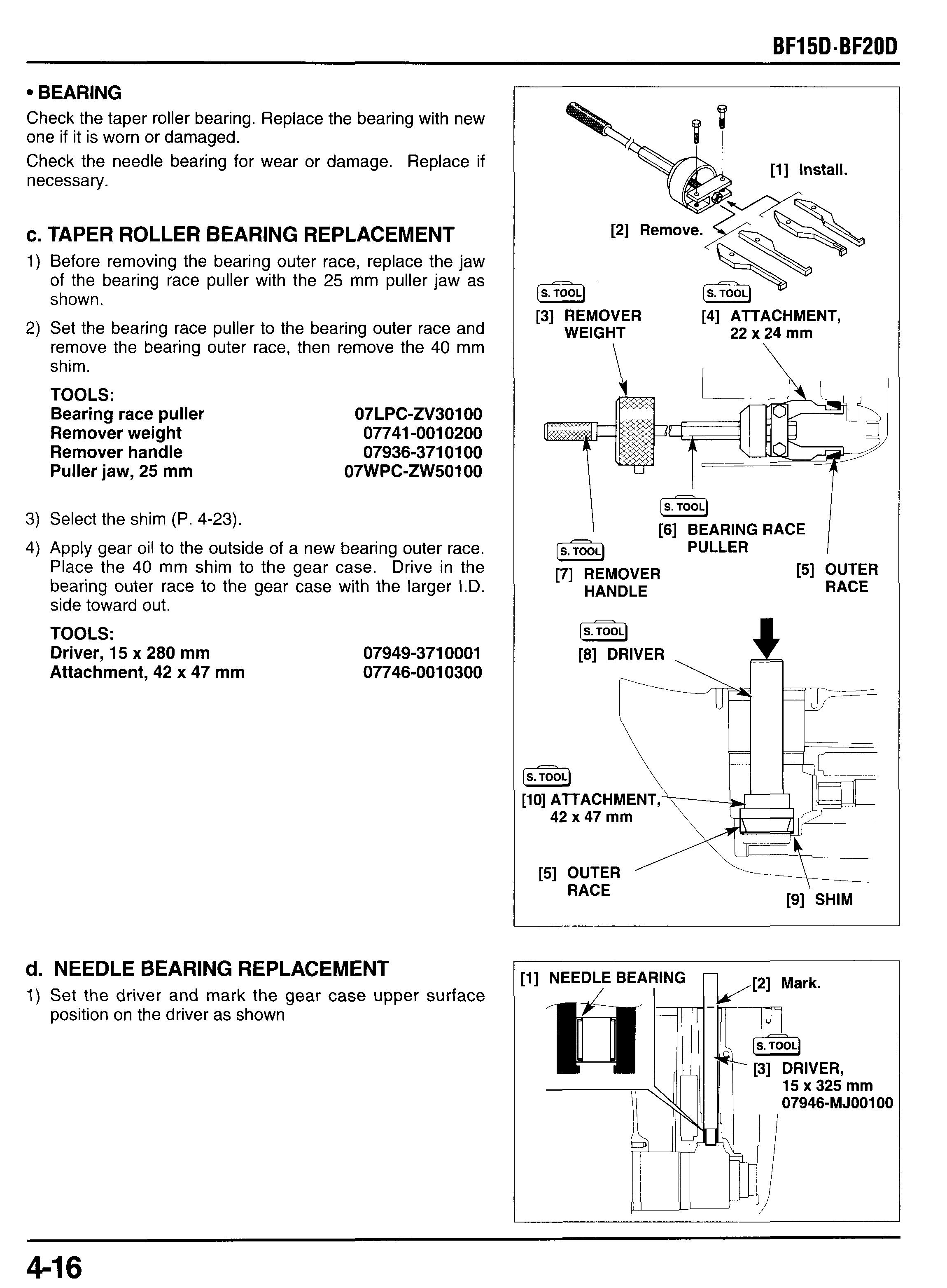
1) Before removing the bearing outer race, replace the jaw of the bearing race puller with the 25 mm puller jaw as shown.
2) Set the bearing race puller to the bearing outer race and remove the bearing outer race, then remove the 40 mm shim.
TOOLS:
3) Select the shim (P. 4-23).
4) Apply gear oil to the outside of a new bearing outer race. Place the 40 mm shim to the gear case. Drive in the bearing outer race to the gear case with the larger I.D. side toward out.
TOOLS:
15 x 280 mm Attachment, 42 x 47 mm
d. NEEDLE BEARING REPLACEMENT
1) Set the driver and mark the gear case upper surface position on the driver as shown
2) Set the tools and remove the needle bearing and discard it.
Take care not to damage the flange section of the gear case.
TOOLS:
Attachment, 24 x 26 mm
Attachment, 32 x 35 mm
Installer shaft
Bearing installer
07746-0010700
07746-0010100
07VMF-KZ30200
070PD-ZYlOlOO
3) Apply gear oil to outer surface of a new needle bearing.
4) Drive in the needle bearing to the marked position with the marked side toward out.
TOOLS:
Driver, 15 x 325 mm pmwz
[S.] [S.TOOJ
121 INSTALLER [3] ATTACHMENT, SHAFT 24 x 26 rnm \ / (s.]
[l] ATTACHMENT, \ \ 32 x 35 rnrn
07946-MJ00100
Drive in up to the mark on the driver that had been put before removal.
Do not drive in too deep beyond the mark, as it damages the flange.
[4] FLANGE --jf SECTION
[5] BEARING INSTALLER
[7] DRIVER, 15 x 325 rnrn , Install with marked side facing toward out.
[6] NEEDLE BEARING
[9] FLANGE SECTION Take care not to damage the flange section.
[IOITHRUST WASHER
7---SELECTION:I--[8]
When replacing the gear case, vertical shaft and/or taper roller bearing, select the shim according to the procedure of the Shim Selection on page 4-23. [l]
NEEDLE BEARING
2) Apply gear oil to the taper roller bearing inner race.
3) Install the taper roller bearing inner race to the forward
4) Install the forward bevel gear and taper roller bearing to bevel gear. the gear case.
[l]
5) Install the vertical shaft into the gear case.
Take care not to damage the water seal lip of the water pump housing.
6) Install the thrust washer, pinion gear shim (see page 3-23
7) Install a new E-clip using a commercially available snap for shim selection) and pinion gear. ring installer taking care not to bend or deform the E-clip. Do not reuse the removed E-clip.
8) Install the following: -water pump (P. 4-16).
- propeller shaft holder (P. 4-8).
- propeller (P. 4-2).
9) Install the gear case assembly (P. 4-10).
[5]
[3]
f. SHIM SELECTION
When replacing the gear case, vertical shaft, and/or taper roller bearing , select the shim as following:
THRUST WASHER (3.5 mm thickness)
Pinion Gear Shim
Select the shim according to the engagement mark on the gear case.
040 mm SHIM
1) Clean the taper roller bearing.
2) Assemble the outer race and inner race of the taper roller bearing and turn the outer race 2 - 3 turns, then measure the bearing height from the outer race end to the inner race end as shown and record the measurement.
3) Cross reference the bearing height and engagement mark on the gear case, and select shim of the appropriate thickness from the shim selection table.
6. WATER PUMP HOUSING
1) Remove the following:
- propeller (P. 4-2).
- propeller shaft holder (P. 4-3).
- gear case assembly (P. 4-9).
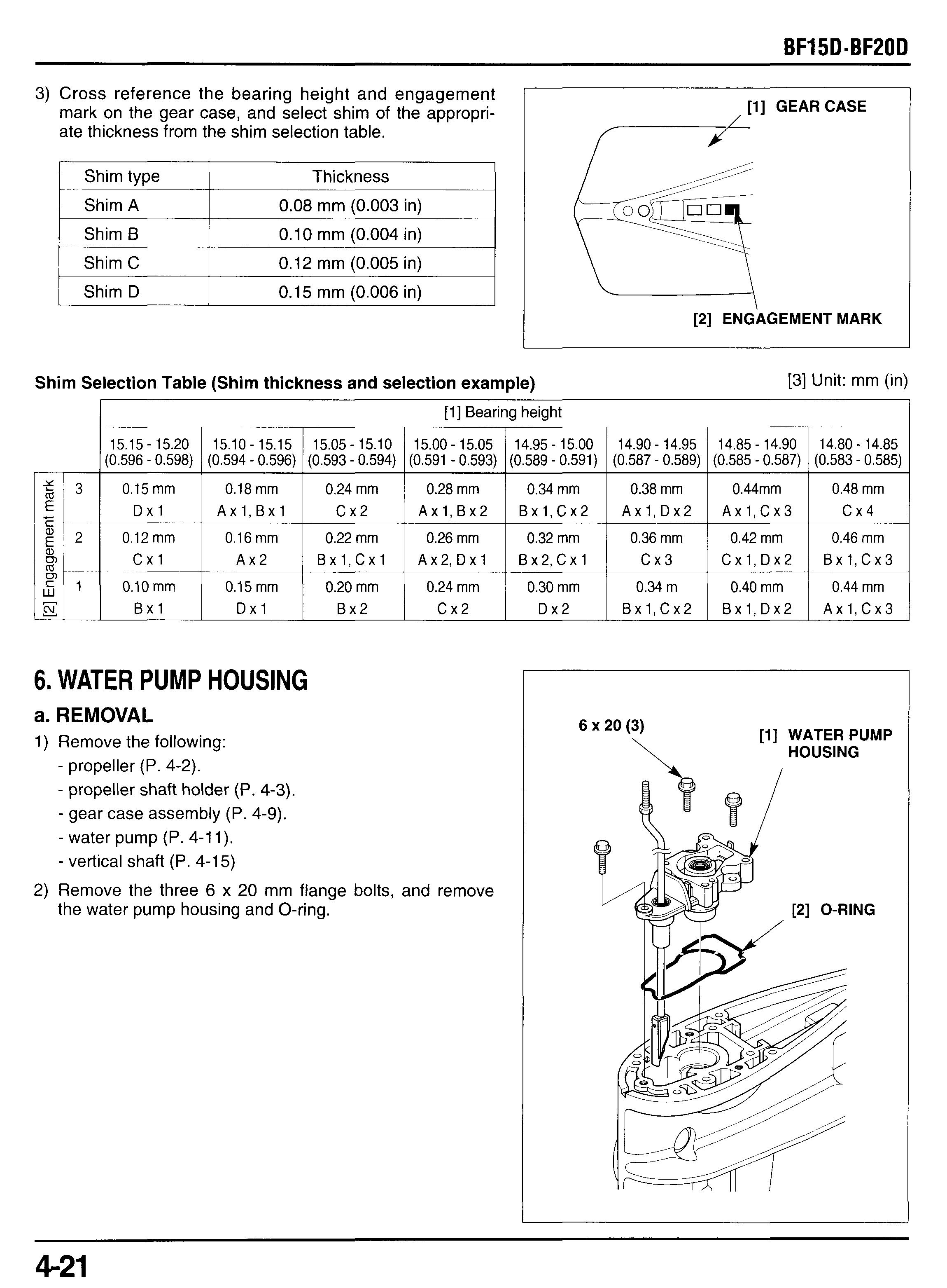
- water pump (P. 4-1 1).
- vertical shaft (P. 4-15)
2) Remove the three 6 x 20 mm flange bolts, and remove the water pump housing and O-ring.
3) Remove the oil guide pip and oil slinger.
b. DISASSEMBLY
1) Drive out the 2.5 x 11.8 mm pin using commercially available pin driver, and remove the push rod from the shift rod B.
2) Drive out the 2.5 x 11.8 mm pin using commercially available pin driver, and remove the shift rod B from the water pump housing.
c. INSPECTION
WATER PUMP HOUSING
Check the water seals and needle bearing for wear or damage.
Replace if necessary (P. 4-23).
d. 15 x 24 x 5 mm WATER SEAL REPLACEMENT
1) Remove the water seals.
2) Apply soapy water to the outside of new water seals, and install them in the direction as shown using the following tools.
TOOLS:
Driver
Attachment, 24 x 26 mm
Pilot, 15 mm
07749-0010000
07746-0010700
07746-0041500
3) After installation, apply marine grease to the lip of the water seals.
e. NEEDLE BEARING REPLACEMENT
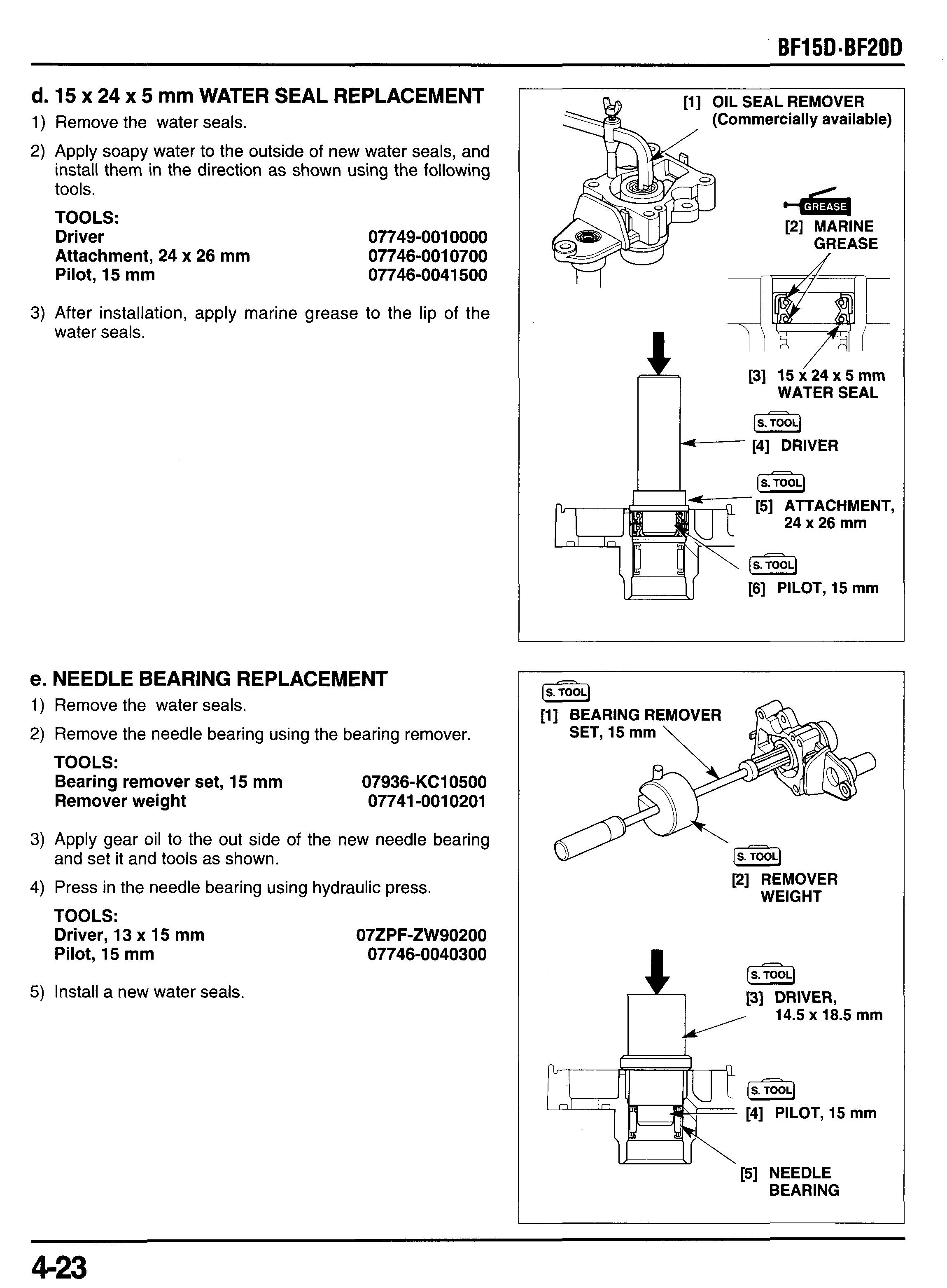
1) Remove the water seals.
2) Remove the needle bearing using the bearing remover.
TOOLS:
Bearing remover set, 15 mm
07936-KC10500
Remover weight 07741-0010201
3) Apply gear oil to the out side of the new needle bearing
4) Press in the needle bearing using hydraulic press. and set it and tools as shown.
TOOLS: Driver, 13 x 15 mm 07ZPF-ZW90200 Pilot, 15 mm a. Clean off any grease or oil from the water seal installa- b. Apply soapy water to the outside of the water seal and
5) Install a new water seals.
1) Install a new 6 mm oil seal, if it was removed; tion area of the water pump housing. install it securely.
2) Apply marine grease to the lip of the water seal.
3) Install the lock nut to the shift rod B and install the shift rod B to the water pump housing.
4) Install the 2.5 x 11.8 mm pin to the shift rod B as shown using a commercially available pin driver. The projected height of the both side of the pin should be equally.
5) Place the shift rod B as shown and set the push rod to the shift rob B noting the installation direction.
6) Align the pin holes of the pu h rod with the pin hole of the shift rod B, and drive the 2.5 x 11.8 mm pin in from the chamfer side using a commercially available pin driver.
7) Install the oil slinger to the gear case by aligning the boss
8) Install the oil guide pipe. with the groove of the gear case as shown.
9) Apply marine grease to the O-ring and install the O-ring to the water pump housing.
10)lnstall the water pump housing assembly to the gear case with the shift slider contacting surface facing toward the propeller side as shown and tighten the four 6 x 20 mm flange bolts.
TORQUE: 12 N*m (1.2 kgf*m, 9 Ibf*ft)
1l)lnstall the following:
- forward bevel gear and vertical shaft (P. 4-18).
- water pump (P. 4-16).
- propeller shaft holder (P. 4-8).
- propeller (P. 4-2).
7. GEAR CAWANODE/ WATER SCREEN
a. DISASSEMBLY/REASSEMBLY
The anodes and water screens can be serviced with the gear case mounted on the outboard motor. After reassembly, fill the gear case with gear oil (P. 3-6). [I1
10 N*m (1.0 kgf*m, 7 Ibfaft)
8. EXTENSION CASE
a. REMOVAL
1) Remove the following:
- engine cover (P. 5-1).
- left and right engine under covers (P. 5-2, 3).
- gear case assembly (P. 4-9).
2) Remove the four 6 x 20 mm flange bolts and lower mount rubber cover.
3) Loosen the 8 x 45 mm upper pinch bolt and remove the lower pinch bolt.
4) Remove the four 8 x 35 mm flange bolt attaching the extension case. mount. case seal.
5) Remove the extension case and lower rubber motor
428
7) Remove the lower rubber motor mount.
8) Remove the 6 x 12 mm flange bolt and set plate, and r remove the water tube and water tube seal.
b. INSTALLATION
LOWER MOUNT RUBBER COVER
1) Apply marine grease to the water tube seal and set it to
2) Set the water tube in the place and secure the set plate the mount case. and 6 x 12 mrn flange bolt.
3) Apply grease to the inside of the lower mount.
4) Install the lower mount rubber to the mount frame.
5) Align the lower pinch bolt hole with the cutout on the mount frame as shown and loosely install the lower pinch bolt
6) Install the two 6 x 10 mm dowel pins onto the extension case.
7) Apply sealant to the sealing surface and install the extension case seal onto the extension case and assemble the extension case to the mount case.
8) Tighten the four 8 x 35 mm flange bolts to the specified torque.
TORQUE: 24 N m (2.4 kgf m, 17 Ibf ft)
9) Tighten the 8 x 45 mm lower mount rubber pinch bolts to the specified torque.
TORQUE: 22 N m (2.2 kgf m, 16 Ibf ft)
10)lnstall the lower mount rubber cover with the boss toward up, and tighten the four 8 x 20 mm flange bolts.
TORQUE: 12 N m (1.2 kgf m, 9 Ibf ft)
11)Reinstallthe following:
- gear case assembly (P. 4-10).
- left and right engine under covers (P. 5-2,3).
- engine cover (P. 5-1).
8. EXHAUST CHAMBER COVER
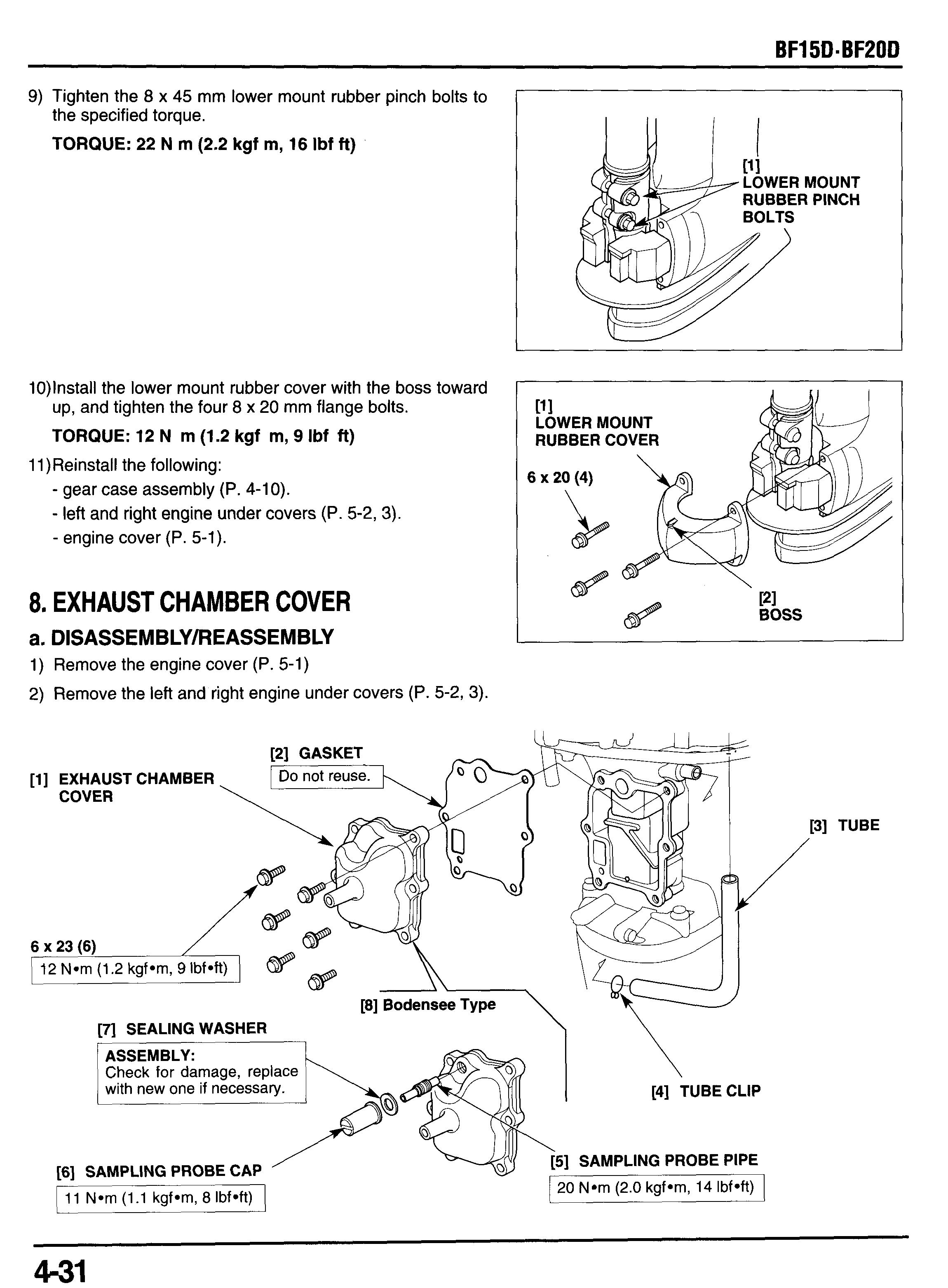
a. DlSASSEMBLYlREASSEMBLY
1) Remove the engine cover (P. 5-1)
2) Remove the left and right engine under covers (P. 5-2, 3).
Check for damage, replace


