
13 minute read
4.8. OPERATING ATTACHMENTS


WARNING
If a control lever is operated while auto idling, the engine speed returns to its original speed.

The left/right control levers control the attachments. The left control lever is for arm, swing; the right control lever is for boom and bucket.
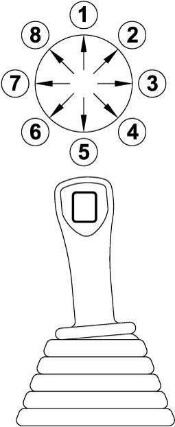
The Left Lever
This lever controls swing and arm.
N Neutral (upper frame and arm are maintained at rest position.)
1: Arm out
2: Arm out and right swing
3: Right swing
4: Arm in and right swing
5: Arm in
6: Arm in and left swing
7: Left swing
8: Arm out and left swing
The Right Lever
This lever controls boom and bucket.
N: Neutral (boom and bucket are maintained at rest position.)
1: Boom lower
2: Boom lower and bucket out
3: Bucket out
4: Boom raise and bucket out
5: Boom raise
6: Boom raise and bucket in
7: Bucket in
8: Boom lower and bucket in
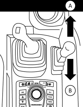
4.9. OPERATING DOZER BLADE AND OUTRIGGERS
Dozer Blade and outriggers are operated with dozer blade and outrigger lever located on right console.
4.9.1. LOWERING OUTRIGGERS / DOZER BLADE
1. Remove the locking pin from outrigger locking hole.
2. Place the locking pin in the storage hole.
3. Secure the locking pin in its storage hole with the cotter pin.
4. Repeat step 2-3 for each outrigger.

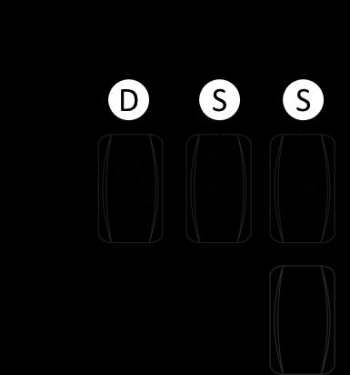
5. Turn each outrigger enabling switch (S) or Dozer Blade enabling switch (D) on.

6. Move the Outrigger Control Lever forward and lower the outriggers completely.
7. Turn each outrigger enabling switch or Dozer Blade enabling switch (D) off.
4.9.2. RAISING OUTRIGGERS
1. Before raising the outriggers turn the excavator to travel position.
2. Press and turn each outrigger enabling switch or Dozer Blade enabling switch (D) on.
3. Move Outrigger Control Lever forward and raise the outriggers completely.
4. Turn each outrigger enabling switch or Dozer Blade enabling switch (D) off.
5. Remove the locking pin from storage hole and insert it to outrigger locking hole.
6. Secure the pin with the cotter pin.
4.10. CRUISE FUNCTION
4.10.1. OPERATING CRUISE FUNCTION WARNING
The cruise function switch set only the engine RPM, not road speed. Engine RPM is set by throttle control dial.
1. Bring the machine to appropriate travel speed.
2. Set the engine RPM by rotating throttle control dial.
3. Press the cruise function switch located on the right console. This switch maintains the engine RPM setting by throttle control dial.
4. Set the appropriate engine RPM by using throttle control dial to either increase or decrease travel speed.
5. To disengage the Cruise Function press brake pedal or position the FNR Switch to neutral (N) or depress the Cruise Function Switch
1. Throttle control dial
2. Cruise function switch
4.11. PROHIBITIONS DURING OPERATION


Working By Swing Force

Never perform raking over the ground, demolition of buildings or thrusting bucket tooth into the ground by using swing force. This operation may cause damage to the machine and attachments.
Working By Travelling Force
Never perform digging by traveling force, and thrusting bucket tooth into the ground. This can overload the rear of the machine and cause damage

Extending The Hydraulic Cylinder To Stroke End
Never operate the cylinder to its stroke end. This can overload the stopper in the cylinder and shorten the life span of the machine. Work with as much clearance as possible.
Working By Bucket Drop Force
Never perform digging by dropping the boom, or using the bucket instead of a pick. Striking digging or continuous striking can overload the rear of the machine or damage the attachment. Also it is very dangerous.
Working By Drop Force Of The Machine Body
Never operate by dropping the machine body.
Digging Rocks
Break the hard rock area using a breaker, and then perform digging to avoid damaging the machine and to improve work efficiency.
Warning
Remove side cutters of the buckets before working with rocks. Otherwise they may be broken. Use for digging only.
Lifting

For hydraulic excavators used in lifting operations, the machine must be equipped with a safety device and overload warning system. When lifting is done without this safety device and warning system, the operator and/or owner will be responsible for the injury (see 4 16).
Caution When Controlling The Levers
Never start up abruptly . Never change direction abruptly from forward to reverse or reverse to forward.


Never stop abruptly while you are traveling at high speed.
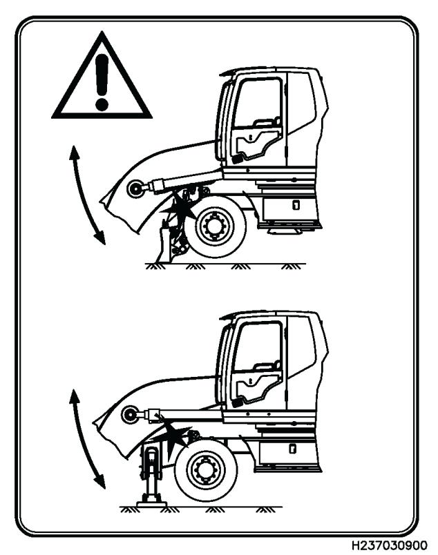
Caution When Lowering The Boom And Swinging The Machine
When retracting the boom cylinders and lowering the boom, the boom may crash to the dozer blade or outriggers.
WARNING
Do not lower the boom too much. When the boom lowered do not swing the machine. Otherwise attachments may damaged.
4.12. CAUTIONS DURING OPERATION CAUTION WHEN TRAVELING

Avoid running the machine over obstacles such as rocks or demolition debris. Such an operation may cause damage to the machine (especially the undercarriage). Therefore, remove the obstacle or make a detour. If it is not possible, lower the attachment close to the ground, and pass over the center of the tires slowly. If the obstacle causes the machine to lean more than 10°, never pass over it, travel around it.
Low Speed Travel On Uneven Ground
Keep the machine at low speed on uneven ground like rock or irregular area.
Permissible Depth Of Water Warning

When traveling out of water, the engine fan will be damaged if the rear of upper body is submerged under the water.
Be careful not to immerse the rear part of the upper structure in the water.
1. Do not operate equipment when front and rear axles, transmission, are under water.
2. It is possible to work and travel in shallow water if the ground is stable. If the terrain is rough or if the water is flowing heavy it is unsafe to operate the equipment.
3. When working in wet soil, the equipment can sink into the soft ground. Select solid ground to secure the equipment before starting work.
4.13. CAUTIONS WHEN TRAVELING ON A SLOPE WARNING
While traveling on a slope, keep the angle between boom and arm at 90 ~110° and raise the bucket 20 ~ 30 cm from the ground. Never descend moving backward on a slope Never change direction or travel across on a slope. Change direction on level ground, if necessary first come down to level ground and make a detour.

If the machine slides, immediately lower the bucket to the ground.
To the extent possible, do not swing or operate the attachments unless it is necessary. The machine can turn over due to unbalance. Especially, do not swing with a loaded bucket. In If it is necessary, pile up earth on the slope to make the ground flat and level 0
Never travel on a slope of 30° or more.
Braking When Descending


Turn the travel lever to neutral position to brake on a slope while descending.
In Case Of Shoes Slipping
If the shoes slip on a slope, thrust bucket into the ground, and pull arm to ascend.
In Case Of Engine Failure
In case of engine shut down while traveling on a slope, put the travel lever to neutral position and lower bucket down to the ground, then start the engine.
Caution On A Slope
If the engine shuts down on a slope, do not operate the swing function, since the upper structure could swing under its own weight and cause tipping or side slipping
Be careful when opening or closing the doors on a slope, operational force may be changed rapidly. Keep the doors closed.
Do Not Swing
Descending
Pile Up The Earth
1) In case of descending on a slope of 15° or more, position the machine as illustrated and travel at low speed.
2) In case of ascending on a slope of 15° or more, position the machine as illustrated and travel at low speed.
Ascending

4.14. ADDITIONAL WORKS USING HYDRAULIC EXCAVATORS
The excavator is a multi-task machine capable of being fitted with a multitude of special attachments to perform many types of work. Only the simplest operations are described below.
4.14.1. BACKHOE WORK
For digging work at a lower grade than the machine is located.When the angle between bucket cylinder and links, arm cylinder and arm is set to 90 ° respectively, the work efficiency of each cylinder will be maximum.
In case of digging works, take advantage of this angle to improve the work efficiency. The scope of arm digging work is at the angle of arm from 45 ° forward to 30 ° backward. There may be a little difference according to digging depth. Never use the cylinder up to its stroke end, but only within this range.

4.14.2. SHOVEL WORK
For digging work in places higher than the machine. Bucket is attached in the reverse position.
4.14.3. DITCHING WORK
Install a proper bucket for ditching work. Set tires in accordance with ditching work direction to work effectively.
In case of wide ditching work, ditch both sides in advance, then the center area.
4.14.4. LOADING WORK


Position the dump truck so as to achieve a small swing radius and good visibility for the operator to work effectively.
Also read over the rear of the dump truck, rather than over the side, as this makes the operator’s work easier and increases efficiency.
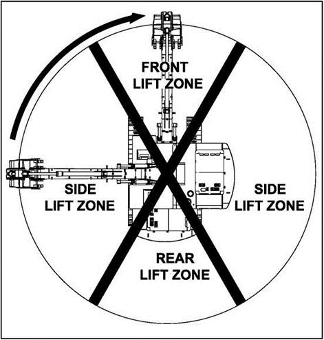
4.15. LIFTING
For hydraulic excavators used in lifting operations, care to the following:
In some countries, using an excavator for lifting work may be prohibited by national regulations. The owner and/or operator is responsible to comply with the national regulations.
For hydraulic excavators used in lifting operations, the machine must be equipped with a safety device and overload warning system. When lifting is done without this safety device and warning system, the owner and/or operator will be responsible for the injury.
There is lifting capacity table in the operator’s cab. It is the owner and/or operator responsibility to comply with the table. When loads are not accurately known is to be lifted the owner and/or operator responsible for the job shall ascertain that the weight of the load does not exceed the machine lifting capacity table.
When lifting, care to the following:
To prevent injury, do not exceed the rated load capacity of the machine.
For safe load handling use short slings to prevent excessive load swing.
When a lifting eye is used, the sling/lifting device must be fastened to the eye in a manner that will not allow it to come loose.
Do not lift or swing a load that exceeds machine load rating or in a way that impairs machine stability.
For safety, when lifting see 2.2.6.
Warning
If load is picked up from the sight zone and swung into the side zone, a tip-over could result causing deathly or fatal injury.
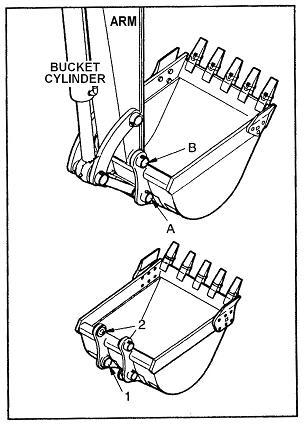
4.16. REPLACING THE BUCKET
WARNING
While striking the bucket pin with a hammer, metal chips may fly into your eyes. Always wear goggles, safety helmets and gloves while working. Block the removed bucket to stabilize it.
Observe the signals when working with other persons.
1) Lower the bucket on to level ground.
When removing the bucket pins, lower the bucket to contact the ground lightly.
2) Remove the pin lock bolt and nut, and remove pins (A), (B), then remove the bucket.
IMPORTANT
Keep the pins clean. Do not damage the dust seals.
3) Align the arm to bucket hole (2) and the link to hole (1), and apply grease, then insert pins (A), (B).

WARNING
Do not insert your fingers into the pin bores to check alignment, a serious injury could occur.
When mounting the bucket, O-ring is apt to be damaged, so put the O-ring at the arm position (see the illustration). When inserting the pin, be careful to insert it into the designated position.
4) Tighten the lock bolt and nut of each pin, and grease the pins.
WARNING
Remove side cutters of the buckets before working with rocks. Otherwise they may be broken. Use for digging only.
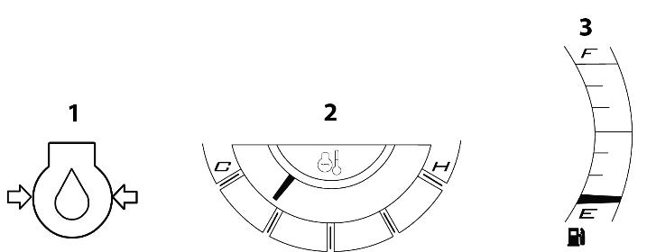
4.17. CHECKS AFTER FINISHING WORK
Before stopping the engine, check the engine, coolant temperature (2), engine oil pressure (1) and remaining fuel level (3).
4.18. STOPPING THE ENGINE IMPORTANT
Stopping the engine before it gets cooled down, affects the service life of the engine. DO NOT suddenly stop the engine except emergencies. If the engine is overheated, cool the engine down in low speeds before stopping.
1. Before stopping the engine, set the engine to idle speed to cool down for approx. 5 minutes. During this cooling down period, check for an abnormality in the engine sound, oil pressure, etc.
2. After confirming that the engine temperature has dropped to the specified level, turn the starter switch to "OFF".
3. Remove the starter key and leave the machine
4. Before turning off the battery master switch, wait at least 10 minutes or more.

Systems such as the engine controller (ECM) and SCR controller (DCU) continue to operate for approximately 10 minutes after the engine is stopped. This systems may malfunction if the battery power is turned off while these systems are still operating.
During this period inspect the machine as described in “4.22 Inspections after stopping the engine”.
Caution
Stopping the engine immediately after driving may cause a failure such as a seizure. Stop the engine after the engine temperature has dropped.
Make sure to place the starter switch in the "OFF" position after the engine is stopped or when the engine is left unused for a long time. Otherwise the battery may run out.
4.19. CHECK AFTER STOPPING THE ENGINE
Check the machine for leakage of oil or water, and defects of the attachments and the tires.
Always refill the engine’s fuel tank completely after engine operation. By minimizing the amount of air in the fuel tank, moisture (air’s water content), freezing, corrosion causes and starting difficulties reduce.
Under 0 C, drain water from the fuel tank and prefilter to prevent freezing.
Remove papers or dead leaves from the engine compartment to prevent fire.
Remove soil deposits and debris from the axles and tires. In freezing conditions after cleaning the tires park the machine on wood planks.
4.20. HANDLING THE ENGINE WITH TURBOCHARGER
4.20.1. PRECAUTIONSDURING STARTINGTHE ENGINE
For the engine starting procedure, refer to chapter "4.2. Starting the Engine".
Caution
When the engine is cold, do not rev it with the gear placed in the neutral position.
When starting the engine after it that has been left unused for a long period of time (one month or longer), perform the following works:
1. With the air intake duct and oil inlet pipe being removed, add the engine oil to the turbocharger from the oil inlet port.
2. Then, rotate the impeller by hand to lubricate the bearing adequately.
3. When adding the oil, make sure that foreign matters such as dust do not enter from the filler port.
4. When oil adding is finished, securely install the oil pipe and the air intake duct.
4.20.2. PRECAUTIONS DURING STOPPING THE ENGINE
Before stopping the engine, make sure to idle the engine for approx. 3 minutes. After driving is performed under a severe condition, idle the engine for approx. 5 minutes until the turbocharger is cooled down.
CAUTION
For the engine with the turbocharger equipped, when the engine is stopped suddenly, the lubricated section on the turbocharger get dried from the high heat, leading to a turbocharger failure.
4.21. LOCKING SYSTEM

Lock at the following locations:
1.
4.22. TRANSPORTATION WARNING
When transporting the machine, the related laws and regulations governing the weight, width, height, length and securing of a load must be taken into consideration.
4.22.1. LOADING AND UNLOADING WARNING
Be extremely cautious during loading and unloading.
Operate the engine at low rpm, and set machine travel speed to LOW.
Choose a firm, level place, and keep at adequate distance from the road shoulder.
Make sure that the ramp is strong enough to bear the machine to be loaded/unloaded. If they bend excessively, support with blocks.
Remove grease, oil, mud, ice etc. from the ramp and the trailer bed to prevent the machine from slipping sideways.
Never maneuver on the ramp. If it is unavoidable, first descend from the ramp and then change course.
When swinging on the trailer, operate slowly because the base is unstable.
After loading, block each tire and secure the machine with tie downs of adequate load rating that the machine cannot move. Cover the exhaust pipe to prevent any damage to the turbocharger. Lock the cab door and lower the antenna.
Make sure to use the loading platforms for loading and unloading.
1) Apply the brake of the trailer, and insert blocks beneath the tires. Fix the loading platforms securely. Check whether the right and the left loading platforms are of same height respectively.
Be sure that the angle of loading platform is 15° or less.
Arrange the distance between loading platforms in such a way that they are aligned with the tires
If you have to travel across a bridge, make sure that its capacity is rated for the weight of the machine and that it is wide enough.
2) Always travel at low speed.
3) Decide the direction and travel slowly onto the loading platforms. Load or unload the machine so that the attachments do not interfere with the trailer.
Never operate any levers other than the travel lever while the machine is on the loading platform.
4) Load the machine on the trailer properly and ensure it is firmly secured.
4.22.2. CAUTIONS ON LOADING
WARNING
Load the machine in a level and firm place, and keep ample distance from the side edge of platforms, ramps and road shoulder.
After loading the machine on the trailer, tie down the machine firmly and securely.
1) Extend the boom and the arm cylinders up to their stroke end, and lower the boom with care
4) Block the machine by putting wedge blocks in both directions of all tires of the machine to prevent sliding on the trailer.
IMPORTANT
Insert chock between the bucket and the trailer to prevent damage of the bucket cylinder during transportation.
Do not allow the bucket cylinder rod to be in contact with any part of the trailer
2) Stop the engine and remove the starter key.
3) Engage the safety locking system securely.
Warning
The SAFETY LOCK LEVER must be pulled in LOCKED position to prevent machine controls from an accidental movement. The operator must lock the safety lever before he leaves the operator’s seat and especially during maintenance and repair work unless it is necessary to operate the machine for this purpose.
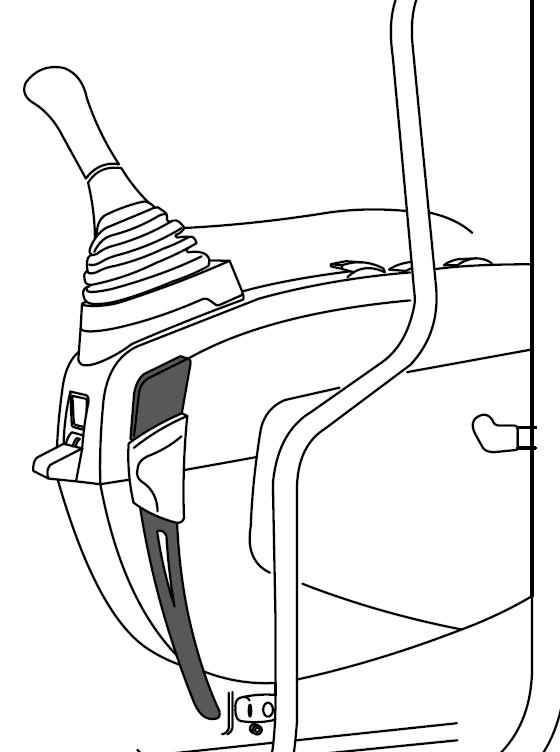
If not, an accidental movement of any control lever will cause the machine or an attachment to move, and will cause serious injury or death. When the safety lock lever is at straight position, the safety locking system is UNLOCKED. Make sure to rotate safety lock lever down to correctly engage the LOCKED position. "LOCKED"
5) Secure the machine by using chains as seen in the figure. Determine chain attaching points on the trailer so that chain angle will be approximately 45 degrees. Tighten all the chains.
4.22.3. PRECAUTIONS ON TRANSPORTATION
WARNING
Choose a transport route in consideration of overpass clearances, bridge and road load limits, wide load prohibitions and travel hours. Obey all regulations governing transportation of the machine.
IMPORTANT
Close and lock the operators cab door. Cover the exhaust pipe.
See Chapter 3.17. “SAFETY LOCKING DEVICE".


