
32 minute read
4.22.4. LIFTING THE MACHINE


Danger
1. Crane operator should be well-trained and certified by an accredited crane operator testing organization.
2. Stop the engine. Take all safety precautions given in the operating & maintenance manual.
3. Hold the machine parallel to the ground when lifting.
4. Use certified cables, slings, shackles and hooks of adequate load rating.
5. Do not apply dynamic force to the cables and lifting equipment.
6. Never lift the machine while there is a person in the cab or on the machine.
7. Keep people away from the working area. Do not let anybody stay under or around the machine.
8. If installed, remove the optional attachments. Optional attachments mayaffect the balance of the machine.
9. Lift the machine from a level and firm ground.
10. Never lift the machine in the way other than shown below. Improper lifting can cause load to shift and cause injury.
11. Read, understand and obey all local and national regulations.
5) Secure the machine by using chains as seen in the figure. Determine chain attaching points on the trailer so that chain angle will be approximately 45 degrees. Tighten all the chains.
Lift the machine evenly from a level and firm ground.
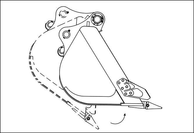
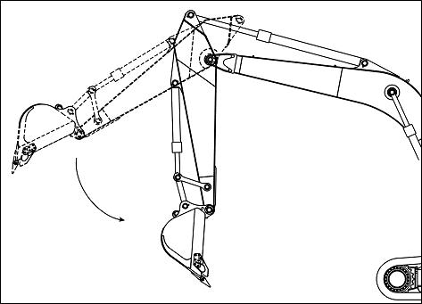
1) Start the engine, and set the attachments as illustrated. Make the upper structure face forward Lower the outriggers to the ground
2) Engage safety locking device.
3) Stop the engine, check the safety around the machine, and then get off. Close and lock the operator’s cab door, front windshield and engine hood securely.
4) As shown in the illustration, insert the lifting device with sufficient strength to carry the weight of the machine. On the front side, attach the wire rope around the boom At rear side insert the wire rope under the outriggers and attach both sides to the lifting device on the top.

5) After installing all hoisting equipment, lift the machine a little to check its balance, if ok lift it slowly and evenly.
DANGER
Never attempt to lift the machine by using the lifting eyes of the counterweight. Lifting eyes should break off due to excessive weight which may cause injury and damage.
4.22.5. SEA TRANSPORT


In case of transportation by sea some components of the machine, which have a probability of forming rust, will be coated with antirust agent. Additionally duck covering wrapped around hydraulic cylinder rods are also covered with canvas.
IMPORTANT
Before operating the machine, remove the duck covering (protector for rust) wrapped around cylinder rods. Otherwise, water will collect inside the cover and cause to occur corrosion. The other reason for necessity of removing duck covering is, squeezing into the cylinder gland and rod while operating the machine with duck covering.
IMPORTANT
Ensure that there is no residual salt on the machine. Wash the machine after receiving. Do not use high pressure while cleaning. Do not use water directly to electrical parts, wiring, battery or alternator. Clean residual antirust oil spray. If the machine is not going to be operated for a long time after receiving, please see the part about machine storage in the operating and maintenance manual and apply instructions.
4.23. PREPARING THE MACHINE BASED ON WEATHER CONDITIONS
4.23.1. PREPARATION FOR COLD WEATHER
In cold weather, starting may be difficult and coolant may freeze, prepare the machine for starting as follows:
4.23.1.1. FUEL AND LUBRICANT
Use fuel and lubricant that have lower viscosity. Specified viscosity ► Refer to Chapter 6.2. "Oil, Fuel, Coolant And Diesel Exhaust Fluid". In cold weather start the engine according to procedures mentioned in Chapter 4.2.2. “Starting in Cold Weather”. About procedures for warming up the machine, consult to Chapter 4.3. “Warm-up Operation”.
4.23.1.2.
Coolant
WARNING
Antifreeze solution is flammable. Keep away any source of open flame.
This machine is shipped with a concentration of 50% ethylene glycol antifreeze and 50% water for protection against temperatures down to -37°C.
Caution on using antifreeze solutions:
- Use antifreeze that does not contain any Nitrites, Amines or Phosphates.
- Use water mentioned in Chapter 6.2.5. Coolant.
- Flush the cooling system in a period of time given in inspection and maintenance list and refill it.
- Use an antifreeze solution throughout all seasons. It will minimize the corrosion and elevate the boiling point of the coolant in hot weather despite a reduction in the cooling efficiency.
4.23.1.3. BATTERY WARNING
A battery gas (hydrogen) is flammable. Do not expose to a sources of fire such as open flame, cigarettes, or sparks.
If battery electrolyte is splashed onto clothes or skin, immediately flush with clean water. If battery electrolyte is splashed into the eyes, immediately wash with plenty of clean water and consult a doctor.
In cold weather, the battery capacity will be reduced. If the charging rate is low, the battery may freeze, so keep the battery 100% charged. Be careful regarding the charging state of the batteries when using heating devices in cold weather.
Refer to the table below to check the specific gravity of electrolyte and calculate the charging rate.
4.23.2. PRECAUTIONS AFTER FINISHING WORK
Pay attention to the following points for sake of a smooth start the next day.
Remove clay grease or water from the machine. If the water on the hydraulic cylinder rod is frozen, the seal may be damaged. Clean it completely. Park the machine on firm and dry ground. In unavoidable case, park it on wooden planks to prevent the tires from freezing on the ground. Under 0˚C, drain water from the fuel tank and prefilter to prevent freezing.
In cold weather, the battery capacity is low. Cover battery or separate it from the machine and store in a warm place. Install it to the machine again the next day.
To prevent the battery from freezing, top up the electrolyte level with distilled water at the beginning of the days’ work and ensure the charging system is fully operational.
4.23.3. PREPARATION FOR HOT WEATHER
In hot weather, perform the following:
Replace the oil or fuel with specified viscosity in accordance with Chapter 6.2. "Oil, Fuel, Coolant And Diesel Exhaust Fluid".
4.24. LONG TERM STORAGE

Some specific precautions must be taken when machines are not used for a long time especially in winter and are stored for a long term. Checking procedures before and during the period of storage, and process which should be followed at the end of the storage period when the machine is to be used again are mentioned below.
4.24.1. BEFORE LONG TERM STORAGE
Follow the processes below before storage:
1. Clean and dry all parts of the machine and keep the machine in a good ventilated area. If the machine is kept in open air, then place the attachments as shown below. Put wedges under the crawler and cover the machine.
2. Inflate the tires up to the working pressure. If it is possible, put wedges under the differentials to remove the load from the wheels.
3. Change all the oil in the machine.
4. Replace all the filters with new ones.
5. Fill the fuel tank and keep it full.
6. Cover all bare surfaces of the cylinders with grease.
7. If available, cut off the battery relay.
8. Disconnect the battery cables and cover them or keep them separately.
9. In cold weather (if the temperature is 0°C or lower), be sure that the amount of antifreeze is adequate against freezing.
10. Keep all the joysticks or control levers in neutral position. Activate the safety lever.
11. Lock the fuel and hydraulic tank breather.
12. Cover the exhaust and suction points.
13. Cover all uncovered holes of bolts, nuts and plugs (like eyebolt of the counterweight and boom)
4.24.2. DURING LONG TERM STORAGE
During the period of storage, follow the steps mentioned below once a month:
1. To lubricate the movable parts. First, idle the machine for 5 minutes.
2. Then, fully extend and retract all the cylinders 3 times.
3. Move the machine in all gears and to all directions approximately 10 meters.
4. Fully turn the steering wheel in both directions 2 or 3 times.
5. If available run the air conditioner. Before starting the machine:
1. Clean all the grease on the surface of hydraulic cylinders.
2. Check the general appearance, color and corrosion protection of the machine.
3. Check all hydraulic cylinder surfaces of the machine.
4. Check all oil and coolant levels of the machine.
5. Check the machine for oil, coolant and fuel leakage. If there is any leakage, fix it before filling up.
6. Check the pressure of the tires.
7. Shaft control: Grease the shafts if the machine is kept in a storage more than 6 months.
8. Check the functions of the levers, doors, windows, and also check the cover plates, cowling of the machine.
WARNING
In case of operating in a closed area, open all windows to ventilate the room because of the exhaust gases.
4.24.3. END OF THE LONG TERM STORAGE
At the end of the long term storage, before using the machine, follow the steps below:
1. Clean all parts of the machine and clean the grease on the surface of hydraulic cylinders.
2. Check all the levels of fluid and if necessary fill it.
3. Check if there is any leakage or any wear on the belts and on the hoses of the machine.
4. Adjust the alternator and fan belt tension.
5. Grease all the grease nipples.
6. Start the engine and warm up the machine slowly up to the working temperature and check all the systems of the machine.
Warning
The piston rods of hydraulic cylinders are coated with grease to prevent rust. Remove the grease before working. Coat the piston rods of hydraulic cylinders with grease in long-term (more than one month) storage.
Caution
When using the engine that has not been used for a long period of time (one month or longer), perform an inspection thoroughly before starting the engine. Also, confirm that there is no oil leakage and the oil has been sufficiently added to the specified level. If the oil level is insufficient, the oil is not supplied adequately, and a breakdown may result.
Replace the DEF/AdBlue® inside the DEF/AdBlue® tank if it is not used for a year or more. Failure to do so may result in a failure of the urea SCR system. Start the engine and idle it at least for 10 minutes. Also, make sure that the engine produces no abnormal noise.
For warming up operation, refer to "4.3. Warm-up Operation".
4.25. INSTRUCTIONS ON WITHDRAWAL FROM USE AND UTILIZATION
Excavator is a machine with a limited operating life like any other mechanism. When its operating life comes to its end, the machine should be dissembled as scrap. Some parts should be gathered to be used as secondary raw material, others should be discarded as scrap and the ones in the third category should be given to special companies for safe extraction and proper disposal of environmentally harmful materials.
Excavators should be dissembled under the following procedure to be discarded as scrap:
Remove all hoses and flexible tubes, and drain hydraulic oil into previously prepared containers.
Dismantle all hydraulic cylinders and drain the oil inside them into previously prepared containers.
Remove all gaskets and seals from hydraulic cylinders and gather them to be sent to hazardous substance disposal sites. Other parts of the cylinders are made of ferrous metals and subject to scrap metalcollection.
Remove fillings of hydraulic cylinders and gather them to be sent to hazardous substance disposal sites.
Remove plastic parts, plain slide ways, slide shoe bearing of rack-bars, pilot ring of fillings and gaskets, bushings, and gather them to be sent for recycling.
Drain hypoid oil from wheel loaders undercarriage into the previously prepared containers.
Remove grease from all parts and gather it into the same container for used oil.
Remaining parts of the cylinders are made of metals. Most of them are made of steel, and only guide bush is made of bronze. All these metalscan be recycled and used again formanufacture.
Caution
Hydraulic oil and grease, even biodegradable, are very environmentally harmful. Avoid its contacting soil and its being absorbed by soil!
Other disassembled parts, components and materials should be treated as follows:
Metal parts: can be sent for scrap to be recycled.
Plastic parts: can be gathered and sent for recycling, if this is impossible – can be sent for scrap with other waste materials.
Oil and grease: can be sent to specialized companies for proper disposal of environmentally harmful materials and stuff (for burning and recycling).
Flexible tubes are usual wastes. If possible, we recommend to remove metal braids and send them for scrap. Hoses can be sent to the dump.
Gaskets and seals: can be sent to the dump.
Filter fillings: can be sent to specialized companies for proper disposal of hazardous substances (oil). The same procedure is for oilyrag and oily saw dusts.
5. TROUBLESHOOTING
5.1. WHEN TO SUSPECT A TROUBLE CASE
When the engine is running at low speed, the following conditions are considered normal. When pulling the arm forward, the arm speed becomes slow for an instant at almost vertical position

5.2. TOWING METHOD
Caution
Make sure that the towing vehicle can handle the weight of the unit being towed and that it has adequate braking capacity.
Never use a damaged wire rope or chain. They could break and cause a serious accident. Always wear gloves when handling a chain or wire rope.
When towing excavator use a wire rope or chain capable of handling the load.
Insert protective material such as thick cloths between frame and wire rope to prevent the wire rope from being damage.
There is an emergency actuating device on transmission to tow the machine in an emergency. The emergency actuating device is to interrupt the power flow between input and output in case of a control pressure failure or a hydro-motor defect and thus allows an emergency towing of the vehicle.
The bucket speed becomes slow for an instant at almost parallel position.
Maximum towing speed: 10 km/h
Maximum towing distance: 5 km
Since there is no transmission lubrication, damages may occur due to lacking oil supply if the instructions are not observed.
For a longer distance it is best to have transported the defective vehicle on a low loader.
Activate the emergency actuation:
Switch off the engine.
Block the vehicle against rolling away.
Grease, nipple (1) by means of a grease gun pump until it comes visibly out at the pressure relief valve of the emergency actuation (3).
Deactivate the emergency actuation:
At the end and start of swing work, the brake valve makes a little noise.
When descending down a slope at low speed, the travel motor makes a little noise and vibration.
Open the bleeder (2) of the emergency actuation device.
Shift into road speed (2. gear) (by doing this, you will automatically apply 30-35 bar control pressure).
Grease will come out of the bleeder.
Then close the bleeder again.
WARNING
If the emergency actuating device is deactivated incorrectly, the transmission will be damaged during operation.
Emergency actuation deactivated:
Emergency actuation activated:
No
Name
1 : Set of springs (plate spring), for multi plate clutch
2 : Clutch, piston
3 : Multi-plate clutch
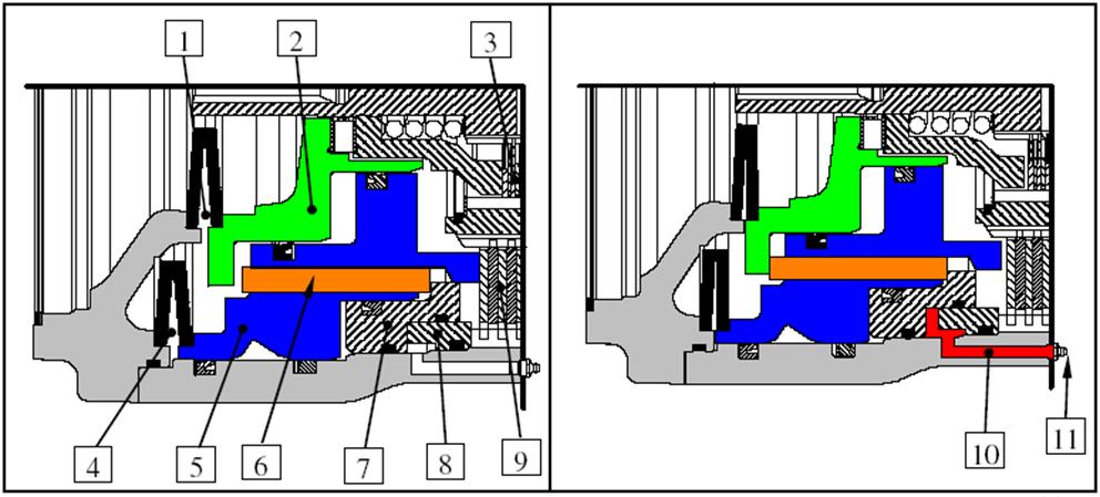
4 : Set of springs (plate spring), for multi plate brake
5 : Brake piston
6 : Pin
7 : Pressure ring for the emergency
8 : Ring for the emergency actuation
9 : Multi-plate brake
10 : Grease
11 : Grease nipple
Grease is applied to the pressure ring (7) pushing the brake piston (5) to the input housing until contact and thus the clutch piston (2) is driven over 2 pins (6).
WARNING
No braking effect of the parking brake, when the release device is actuated. No gear must be selected if the emergency control is activated.
5.3. TOWING HOLE FOR LIGHT OBJECTS
WARNING
Be sure to use shackles. Make sure you attach the rope horizontal to the lower chassis
Move the machine slowly.
Towing shackle hole for light objects is located in the lower frame.
5.4. CAUTIONS UNDER SPECIAL CIRCUMSTANCES
Lubrication of attachments in severe applications
When working in water the attachment pins that are submerged during the work cycle should be greased every few hours and upon completion of the days’ work.
When working under over load conditions, or digging in deep and wet locations, grease the attachment pins at regular intervals during the shift and at the end of the day’s work.
After greasing, operate the arm, boom and bucket several times, then grease again.
5.5. ELECTRIC DISCHARGE WARNING
Battery fumes (gases) can explode; keep open flame, burning cigarettes and sparks away from the battery.
Battery electrolyte can damage clothes, burn skin and cause blindness. If electrolyte is splashed onto your skin or into your eyes flush with plenty of clean water for 10~15 minutes and immediately get medical help.
Always wear goggles or safety glasses when handling the battery.
When removing battery terminals: disconnect the (-) terminal first
When installing battery terminals connect the (+) terminal first.
Avoid contact between the (+) terminal and the machine chassis, sparks may occur and cause explosion.
Avoid loose terminal, sparks may occur due to poor contact.
5.5.1. STARTING THE ENGINE WITH BOOSTER CABLES (JUMP START)
When starting the engine with booster cables, observe the following.
CAUTIONS WHEN CONNECTING / DISCONNECTING THE BOOSTER CABLES
WARNING
When you start the engine with booster cables, wear safety goggles. Ensure the positive (+) terminal does not contact the negative (-) terminal when connecting the cables.
When starting the engine from another machine, be careful that the source machine does not contact the disabled machine. Prevent sparks around the battery; they could cause battery gases to explode.
Make sure that the booster cable connections are correct. The last cable is connected to the upper structure, but it should be connected as far from the battery as possible. (However, do not connect to the attachments).
When disconnecting the booster cables from the battery, disconnect in the reverse order.
Important
Booster cables and clips should be sized according to the battery capacity
Use the same capacity battery and system voltage as the disabled machine
Do not use corroded or damaged cables and clips.
Connect the clips firmly
Connecting Booster Cable
Turn the start switch to STOP position, and connect the booster cables in numbering order shown in the figure.
Turn the start keys of both the disabled machine and the normal machine to STOP position. Connect the clip (1) of booster cable (A) to the battery positive (+) terminal of the machine to be boost started.
Connect the clip (2) to the battery positive (+) terminal of the engine which is running.
Connect the clip (3) of booster cable (B) to the battery negative (-) terminal of the engine, which is running.
Starting The Engine
Make sure the clips are firmly connected to battery terminals.
Turn the key switch of normal machine to START position, and start the engine.
Turn the key switch of disabled machine to START position, and start the engine. If the engine does not start within 30 seconds, wait for 2 minutes between cranking attempts.
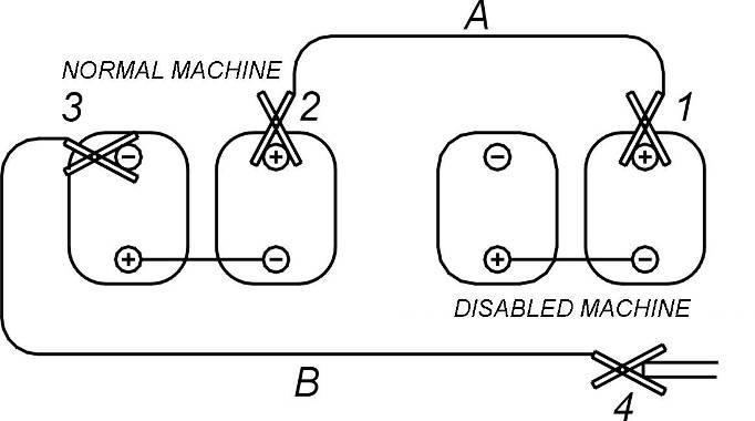
Disconnecting The Booster Cables
After the engine has started, the booster cables must be disconnected in the reverse order. Disconnect clip (4) of the booster cable (B) from the upper structure.
Disconnect clip (3) from the battery negative (-) terminal of the running engine.
Disconnect clip (2) of the booster cable (A) from the battery positive (+) terminal of the running engine.
Disconnect clip (1) from the battery positive (+) terminal of the machine which was boost started
5.6. POOR BATTERY CHARGING
If the charge lamp illuminates while the engine is running. This is an indication of poor battery charging.
Check that the V-belts are correctly tensioned and free of damage.
Check the alternator, relays and other related writing for poor connection or damage. If they are normal, the charging system is faulty. Have the engine inspected by your dealer.
5.7. OVERHEATING WARNING
Never attempt to open the radiator cap when the coolant is hot. Otherwise, hot coolant or steam may suddenly come out and burn you. Wait until the coolant is sufficiently cool before attempting to open the cap. Place a thick cloth over the cap and slowly turn it to open.
Note
Do not stop the engine immediately. Otherwise, the coolant temperature may shoot up, possibly causing the engine to seize.
Top up the coolant little by little. Pouring a large amount of coolant which is at room temperature may cause the engine to crack.
High or low coolant temperatures might lead the engine to failure. Engine coolant temperature should be between 75-90°C.
If engine coolant temperature indicator shows a value higher than the desired range, or if “OVERHEATING” warning message appears on control panel screen, operator must suspect that the engine is facing the very dangerous problem of overheating in the diesel engine.
When the coolant temperature is above the suitable range, fuel delivery to the engine is limited.
Stop the machine and run the engine at a speed slightly higher than idle speed to cool down the engine. When the gauge needle has dropped to the middle range of the scale, or when the coolant temperature warning lamp has gone out, stop the engine and perform the following steps.
1. Check the radiator hoses etc. for coolant leakage.
2. Check the V-belts for damage and proper tension.
3. Check the coolant level as explained in maintenance chapter. If it is necessary to add coolant, wait for the engine to cool down and then add coolant into the coolant reservoir tank.

4. Check that the front side of the radiator is free of trash etc.
5. If coolant is leaking or the engine overheats frequently, this is an indication of a faulty cooling system. Contact your dealer.
Caution
Do not stop the engine when it’s overheated. Operating the engine for a long time while the coolant level is low not only increases fuel and oil consumption of the engine, but also leads to wear damage on the engine and ultimately cause the engine to fail.
2. Coolant reservoir filling cap
5.8. ABNORMAL (LOW) OIL PRESSURE NOTE
Check the oil pressure after the engine has been warmed up. The oil pressure gauge may show a high rating immediately after engine start when the engine is still cold.
If the oil pressure is low or the oil filter is clogged or oil pressure drops below minimum value then "engine oil low pressure indicator" in the instrument panel turns on In this condition, stop the machine and the engine immediately and perform the following steps.
NOTE
Stop the engine immediately. Otherwise, the engine may fail.
1. Check for oil leakage.
2. Check the oil level and top up as required. Refer to Chapter 6.5.5. "Checking Engine Oil Level".
3. If the oil level is correct, but the oil pressure gauge needle indicates an abnormal pressure or the low oil pressure warning lamp or the oil filter warning lamp illuminates, contact your dealer.
Dependably performing inspection and maintenance prevents faults. Make sure to perform all inspection and maintenance services periodically. Also, quickly fix any small faults to prevent those leading serious faults. When any of the failures listed below occurs, perform inspection and take action following the table. If a repair cannot be performed by yourself, the corrective action shown in the table does not eliminate the problem or a failure location cannot be identified, contact the nearest Hidromek Authorized Service.
Caution
In the "Corrective Action" column indicates that the failure requires a repair or adjustment, so contact the nearest Hidromek Authorized Service.
The exhaust smoke is white
Too
Failure of the engine control system
Failure of the fuel system
Continuous idling for a long period (two or more hours)
Failure of the engine control system
Raise the engine speed and confirm that white smoke is not emitted
Clogging of the air cleaner Replace the element
The exhaust smoke is black
Failure of the fuel system
Clogging of the exhaust system
Urea SCR system is faulty
If you find any problem, look into a possible cause and get it corrected immediatelyto prevent a serious trouble. If you ignore it and continue to operate the machine, it may cause a serious hazard.
: Symbol means; causes mentioned on the list are to be repaired and adjusted by HIDROMEK Service Center. Call the nearest HIDROMEK Service Center.
Refer to the following list to plan your checks and maintenance. If the cause is not clear, call the nearest HIDROMEK Service Center.
Never attempt to check, disassemble or fix the engine, hydraulic system and electric system. Contact HIDROMEK dealer service center.
Symptom Possible Cause Remedy
Battery discharged.
Charge or change.
Starter does not turn or turns weakly.
Battery terminal is disconnected, loose or corroded. Correct corrosive part and tighten securely.
Starter ground terminal is disconnected, loose or corroded. Correct corrosive part and tighten securely.
Engine oil viscosity is too high. Change with oil of correct viscosity.
Starter or electrical system is failure.
Engine emergency shutdown switch is on.
No fuel.
Engine does not start
Starter turns.
Engine starts but stops soon.
Engine emergency shutdown switch is turned off.
Make sure that there is no fuel leakage and replenish.
Air is in fuel system. Bleed air.
Fuel filter is clogged. Remove water and change element.
Fuel is frozen. Make fuel pipes warm with hot water or wait until ambient temperature rises.
Injection pump is failure.
Electromagnetic type fuel pump is failure.
Engine control system is failure.
Engine malfunction indicator lamp and LCD Display panel shows engine failure.
Strainer is clogged.
Pre-heating device is failure. Lowering compression pressure.
Idling is too low
Adjust by idling control equipment on the machine. If adjustment is not possible, contact HIDROMEK dealer.
Fuel filter is clogged. Remove water and change element.
Pre-fuel filter is clogged. Clean or change element.
Strainer is clogged.
Engine control system is failure.
Air cleaner is clogged. Clean or change element.
Injection pump is failure
Electromagnetic type fuel pump is failure.
Engine does not stop. Engine oil is too much. Make correct oil level. If adjustment is not possible, “◎”.
Symptom Possible Cause Remedy
Fuel system is failure.
Engine running is unstable.
Water or air is in fuel system. Bleed air or remove water.
Engine control system is failure.
No coolant. Replenish.
Front of radiator is clogged with dust. Clean with soft brush.
Sub tank cap is not tightened properly. Tighten securely or change sub tank cap.
Engine overheats.
Coolant is fouled. Clean inside of radiator and change coolant.
Oil is in coolant.
Thermostat is failure. Change thermostat.
Engine oil viscosity is not correct. Change with oil of correct viscosity.
Engine oil level is not sufficient. Replenish.
Oil pressure does not rise.
Inside of engine is failure.
Meter, lamp or switch is failure.
Hunting in oil pressure.
Engine oil is too much. Make correct oil level.
Air cleaner is clogged. Clean element.
Fuel filter is clogged. Remove water and change element.
Pre-fuel filter is clogged. Clean element.
Strainer is clogged.
Engine control system is failure.
Engine has no power.
Engine is failure.
Exhaust system is clogged.
Fuel system is failure.
Type of fuel is not correct. Electromagnetic type fuel pump is failure.
5.10. HYDRAULIC SYSTEM
5.10.1. HYDRAULIC PUMP Symptom
Insufficient output of the pump
Malfunction of controller Fix or replace
Cavitation (Remarks: Low boost pressure, air leakage at suction pipe, increased suction resistance)
Damage in piston shoe
Check working oil for emulsion
Replace the piston shoe, plate, etc.,
Abnormal noises and vibrations
Cracking of the cylinder
Wrong installation of the pump
Hunting of the regulator
Regulator failure
Extreme decrease of pump delivery flow and nonincrease of delivery pressure
Seizure or damage inside the pump
Wrong fitting of the regulator piping
5.10.2. TRAVELING, SWINGING AND ATTACHMENT WORKING
Pump malfunction
Insufficient operation oil
Replace the cylinder
Correct installation
Repair the regulator
Repair regulator
Replace damaged part
Correct
Attachment, swing and traveling are impossible
Damage on suction pipe or hose
Gear pump malfunction
Insufficient power on attachment, swing and traveling
Malfunction due to the pump worn out
Decreased pressure setting of main relief valve
Insufficient operation oil
Oil tank strainer blocked by foreign matters
Air intrusion during suction
Bad control valve
Only one side of the levers not work or the power is weak
Loosened connecting parts
Damage on O-Ring on connecting parts
Malfunction of the pump
Symptom Possible Cause Remedy
Spool of control valve damaged
A foreign material on spool
Damage on piping or hoses
Replace
Fix or replace
Fix or replace
Only one function cannot be done.
Loosened connecting parts
Tighten
Damage on O-Ring on connecting parts Replace
Malfunction of motor or cylinder
Replace
Malfunction of traveling or swing reduction gear Replace
Travel problem on both sides Center joint trouble
Travel motor trouble
Fix or replace
Fix or replace
Travel problem on one side
Parking brake trouble
Contamination on oil cooler
Fix or replace
Clean
High operating oil temperature
The low pressure hose leaks
Insufficient tension on engine fan
Loose plug
‘O-ring’ damage
Control lever cannot be operated Pilot control valve trouble
Adjust
Tighten properly
Replace
Fix or replace Control lever span too much Pilot control valve trouble
The control lever inclined on side
Loose bolt of pilot control valve
5.10.3. HYDRAULIC CYLINDERS
Damaged oil seal
Fix or replace
Tighten more
Cylinder does not work or the power is weak
Oil leaking due to cylinder rod failure
Damaged or worn out piston seal
Replace oil seals or hydraulic cylinder
Replace rod or hydraulic cylinder
Fix or replace
The drifts while the machine is stopping
Abnormal wear of control valve spool
Malfunction of main or overload relief valve
Replace
Fix or replace
5.11. ELECTRIC SYSTEM
The lamp fades out or blinks while the engine is running
The battery recharge warning lamp doesn’t work
A terminal is loose or wire disconnected
Inspect, replace if necessary
Loose belt tension Adjust
Alternator trouble
Inspect, replace if necessary
Wire disconnection Inspect, replace if necessary
The alternator generates an abnormal sound Alternator trouble Replace
Wire disconnection Replace
Starter motor doesn’t work while the key is ON
The Bendix pinion of starter motor is faulty
The starter can’t start the engine
The starter motor stops before the engine is started
Engine oil pressure warning lamp doesn’t light up when engine is stopped
Battery recharge warning lamp does not light up when engine is stopped. (Key is ON)
5.12. OTHER TROUBLES
Battery discharge Recharge
Starter motor trouble
Replace
Battery discharged Recharge
Battery discharged Recharge
Starter motor trouble
Wire problem
Replace
Inspect, replace if necessary
Battery discharge Recharge
Monitor trouble
Replace
Wire disconnection Inspect, replace if necessary
Pressure switch trouble Replace
Monitor trouble Replace
Wire problem
Inspect, replace if necessary
6. MAINTENANCE
6.1. CAUTIONS IN MAINTENANCE
All the inspection and maintenance information specified in the manual must be strictly observed. Park the machine on level and firm ground, then perform inspection and maintenance.
Warning
Select a place with flat and firm ground for performing maintenance. It would be very dangerous if the engine started to move. Make sure to stop the engine and pull out the starter key.
When performing works with the electrical system, make sure to disconnect the negative (-) battery terminal.
Do not perform work near an open flame or other heat sources.
Each part on the engine is hot immediately after driving. Be careful not to get burned. Perform inspection when the engine has cooled down. Replacement of each oil and oil filter should be performed when each oil has cooled down sufficiently. Performing work when they are still hot can cause burn injury.
When performing a maintenance work on the fuel line or fuel filter, remove the fuel cap. Since the fuel system is under high pressure, the fuel may overspill unless the pressure is relieved, and the spilled fuel may be ignited, possibly leading to a fire.
Do not leave the engine running in a poorly ventilated indoor place. This could cause carbon monoxide poisoning.
Caution
Use only appropriate tools.
Do not leave the removed parts or tools on the engine. They may damage the equipment if they are caught in the belts or other moving components.
When replacing, take sufficient care so that filth or foreign matter does not attach to the removed component.
Dirty water, dirt and other impurities seriously impair the effectiveness of the oil, and damage the parts, so take sufficient care not to let filth or foreign matter mix into the oil while adding or replacing.
Confirm that all systems and components are normal after performing the work.
6.1.1. HIDROMEK GENUINE SPARE PARTS
When replacing the parts, use only genuine spare parts supplied by HIDROMEK.
6.1.2. WINDOW WASHER FLUID
Use the washer fluid for cars.
6.1.3. OIL AND GREASE
Use clean oil and grease and check if the container is broken. Be careful to keep lubricants contaminant free.
6.1.4. NEVER MIX OILS
Never use different type of oil when changing or adding oil. Never mix different types or brands of oils, even they are recommended by Hidromek.
6.1.5. CHECK HOUR METER
Check the hour meter every day to determine if any periodic maintenance is required.
6.1.6. KEEP THE MACHINE CLEAN
Keep the machine clean to find defects easily. Especially, keep grease fittings, breather, and oil level gauge (oil sight gauge) clean to prevent contamination.
6.1.7. CAUTIONS FOR HOT OIL AND WATER
Draining oil or water and replacing filter immediately after stopping the machine is very dangerous. Wait until the temperature is considerably reduced. If the oil is cold, warm up the oil (about 20°C - 40°C), and then drain it.
6.1.8. CHECK FILTER
When replacing oil and/or filter, check the drained oil and used filter for contamination of metal particles or other foreign materials.
6.1.9. CAUTIONS WHEN ADDING OIL
If oil filler port has a strainer, fill oil without removing it.
6.1.10. KEEP CONTAMINATION AWAY
Inspect and replace oil in a place as clean as possible to protect the components from contamination.
6.1.11. ATTACH WARNING TAG
In case of draining oil or water, attach a warning tag on the control lever or starter switch to prevent risk of operation by others.
6.1.12. OBSERVE ALL WARNINGS AND CAUTIONS
Observe the caution depicted on the plate attached to the machine and caution in this manual thoroughly and work safely.
6.1.13. PRECAUTIONS WHEN WELDING
Disconnect the main power (Turn the starter switch to OFF position and also turn the battery master switch to CUT OFF position.)
Never use 200V or more continuously. Attach the work piece ground clamp within 1 m of the welding point (as close to welding spot as possible).
Be careful that seals or bearings are not in the electrical path between the welding point and the ground clamp.
Avoid setting the ground clamp on fastening pin of attachment or hydraulic cylinder.
Wear protective clothing, goggles, and gloves to make sure your body is insulated from the work piece.
6.1.14. PRECAUTIONS ON FIRE
Use non-flammable solution or light oil to clean the parts. When using light oil, do not expose it to open flame.
6.1.15. CLEANING MACHINED SURFACES
When dismantling parts installed with an O-Ring, gasket and seal, clean the surface and replace them with new ones. Ensure the O-Ring, seal or gasket, etc. are properly installed.
6.1.16. PRECAUTIONS WHEN WASHING THE MACHINE
Never let water or steam contact electronic parts or connectors.
Never let water contact controllers and instrument panel in the operator’s cab.
Never let high-pressure water contact radiator and oil cooler.
6.1.17. CHECK BEFORE AND AFTER WORK
When working on a swampy ground, a shore, under water and snow, check the tightening condition of each plug. After finishing work, wash the machine to check for cracks, damage and loose bolts and nuts. Grease each part sufficiently after finishing work. In case of working under water frequently, replace travel motor oil often regardless of working time, because the oil may be diluted if water gets in it.
6.1.18. PRECAUTIONS DURING WORK IN DUSTY CONDITIONS
When working in dusty environments, check the following.
Clean the radiator and oil cooler core (fin) often to prevent it from being clogged
Clean the electronic parts, especially starter motor, alternator, to protect them from dust.
6.1.19. DISCARDED PARTS, OILS AND OTHER LIQUIDS
Discarded parts, oil, grease and fluids could have an adverse effect on the environment. It is difficult to dispose of these properly, so have a Hidromek Authorized Service handle all inspections and replacements.
When replacing each oil, filter, or coolant, prepare a pan and drain them into the pan.
Disposal and treatment of replaced each component, oil, filter or coolant must be conducted in accordance with the specified procedure.
6.1.20. HIDROMEK RECOMMENDED OILS AND GREASE
Periodical adding and replacement of oils and greases are very essential to maintain the engine performance and to prevent failures.
For Hidromek recommended greases and oils, their quality and performance are guaranteed by Hidromek.
For maintenance and service, use of Hidromek recommended greases and oils is recommended.
Refer to “Chapter 6.2. Oil, Fuel, Coolant and Diesel Exhaust Fluid” for recommended type of fluids.
6.1.21. OIL
Oil used in the engine or hydraulic system is always subject to severe operational conditions (e.g. high temperature, high pressure) over time. Be sure that you use specified type of oil according to work condition described in this manual. Always replace the oil according to specified maintenance schedule even if it is not deteriorated.
Contamination in oil will negatively affect the performance and service life of the components. Keep oil clean and in good condition, prevent contamination during maintenance.
Machine breakdowns are almost always caused by contamination. Especially, when storing or filling the oil, ensure the containers, funnels etc. are clean.
DO NOT mix different brands of oil. Refill the oil to the specified level. Excessive or insufficient oil may cause a breakdown.
If air gets in the circuit, hydraulic oil becomes misty. Contact Hidromek Authorized Service to pinpoint and root out the cause.
When replacing oil, make sure to replace the related filters as well.
Check the condition of the machine and get the oil analyzed periodically. Contact Hidromek Authorized Service.
When the machine is delivered, it is filled with hydraulic oil type ISOVG46.
6.1.22. FUEL
The fuel pump is a high pressure and precision component machined with fine tolerances. If the fuel is contaminated with water or dust, it will cause component failure.
When storing or filling fuel, pay attention to avoid contamination.
Make sure to use correct type of fuel specified in this manual. In lower temperatures, the fuel gels or solidifies, therefore it is crucial to use fuel that best suits the ambient temperature.
After finishing work, refill the fuel tank fully to prevent accumulation of water as the air is condensed in the fuel tank.
Before starting the engine or 10 minutes after refilling the fuel, drain the sediment and water from the fuel tank. Drain the water separator daily.
6.1.23. COOLANT
Never use well, river, sea or waste water in the cooling system since the cooling system can be clogged and damaged. See Part 6.2.5 for quality of water to be used.
When using antifreeze solution, observe the cautions specified in this manual and shown on the container.
When the machine is delivered, the coolant contains 50% antifreeze and %50 water. This antifreeze solution minimizes corrosion, rusting, scaling and formation of sludge in the cooling system. See Part 6.2.5 for life expectancy. The mixing ratio of antifreeze solution depends on outside temperature. See Part 6.2.5 for mixing ratios per temperature.
Should an overheat situation arise, never stop the engine immediately. Cool it down at low idle and stop, then refill the coolant. See Part 6.2.5 for warning.
Use an antifreeze solution throughout all seasons to lower the freezing point and raise the boiling point which will minimize failures such as overheating, pitting of liners, water pump leakage and clogging of radiators.
6.1.24. GREASE
Grease should be used to prevent the rotating parts and the connection parts from wear, seizure and noise.
It is not necessary to replenish the grease nipples which are not specified in periodical maintenance section. These grease nipples are for overhauling or for replacement of grease. After using the machine for a long time, if the machine does not work smoothly, refill the grease. After filling the grease, clean overflowing grease thoroughly. Especially, be careful to clean the rotating parts on which sand and dust might deposit.
6.1.25. STORING OIL AND FUEL
Always comply with regulations governing safe handling and storage of fuel and oil.
If stored outdoors, protect the drums and other containers from external conditions i.e. direct sun beam, rain, snow, sand etc., by storing them under an open sided shelter.
If kept outdoors with no protection, position (tilt) the drums so that water and debris cannot accumulate on the top, or cover with a waterproof tarp. Also turn the drum to put the plugs on a horizontal plane to prevent moisture and impurities being drawn in as the drum expands and contracts. Avoid deterioration of product quality due to longterm storage: use them on a first-in/first-out basis.
6.1.26. DIESEL EXHAUST FLUID (DEF/AdBlue®)
DEF/AdBlue® is a clear, colorless, and harmless aqueous solution. It is normal for DEF/AdBlue® to emit an odor in some circumstances.
DEF/AdBlue® is harmless to the human body even if touched, however, it may cause inflammation in rare circumstances depending on its constitution. In such cases, take the following actions.
In the case of contact with skin, wash off with water. Failure to do so mayresult in irritation for those with sensitive skin.
In case of accidental ingestion, drink one or two glasses of water or milk and consult your physician immediately.
In the case of contact with eyes, immediately wash out with large amount of water for at least 15 minutes and consult your physician.
StoringDEF/AdBlue®
Seal the DEF/AdBlue® container to prevent evaporation and store it indoors or in places that are well ventilated and not exposed to direct sunlight.
When stored, the expiration date of DEF/AdBlue® varies depending on the temperature of the storage location. Contact your Hidromek Authorized Service for details.
DEF/AdBlue® may deteriorate significantly if stored at 35°C or above.
Even if frozen, DEF/AdBlue® retains the same quality as when thawed and is usable as is. When storing or carrying DEF/AdBlue®, use the container in which the DEF/AdBlue® was contained when purchased. If not, use a dedicated polyethylene tank (PE) or stainless steel container that is free from any adhesion of foreign materials such as water or dust.
DisposingofDEF/AdBlue®
Do not dispose of DEF/AdBlue® or its empty containers into lakes, seas, rivers, or other such places.
Dispose of in an appropriate way complying with local legal requirements.
6.1.27. FILTERS
Filters are very important parts to protect oil, fuel and air circuits against impurities. Replace them periodically according to this manual. The periods of filter replacement given in this manual are for recommendations. Operating conditions of the machine may require the filter elements to be replaced more or less often than the service periods recommended in this manual. Never reuse the filter (cartridge type),
When replacing the oil filter, check whether the consumed filter has metal particles on it. If any are found, contact Hidromek Authorized Service. Please obtain genuine filters from HIDROMEK.
6.1.28. ELECTRONIC PARTS
Damaged insulation, accumulation of dirt and water on electronic parts and components may cause electric leakage and lead to machine malfunction. This is very dangerous and must be avoided. Check the fan belt tension, belt damage and the electrolyte level.
Never disconnect or dismantle electronic parts from the machine.
Never use, on the machine, electronic components other than those specified and/or approved by HIDROMEK.
Be careful not to wet the electronic parts when washing the machine, and close the cab windows on rainy days to protect electronic components. The controller of control system may malfunction due to electromagnetic interference. If you have to use a portable phone, consult with Hidromek. When working ashore, keep the electronic parts dry to protect them from corrosion.
When installing electronic equipment like an air conditioner/heater, connect them to their own power connector.
Never connect the optional component power supply circuit directly to starter switch, battery relay, etc.
DO NOT use electric lamp or other high voltage electric devices when troubleshooting on electronic components and systems. Otherwise you will damage them. USE ONLY multimeter and similar accurate electronic measuring instrument designed for this purpose.
6.1.29. HYDRAULIC SYSTEM
The hydraulic components are hot during and soon after working. Also these parts are under high pressure during work and even after the machine is shut off, therefore be careful and observe the followings when performing maintenance and checks on the hydraulic system.
Lower the bucket to the ground level, and release all pressure in the attachment circuits. Stop the engine before performing any maintenance and service on the machine.
Allow oil to cool down.
There is always internal pressure in the hydraulic circuit. Never supply oil or drain oil, and never maintain or check the machine before eliminating the internal pressure. Also, when you loosen the plug and hose connectors, loosen them slowly with extreme care and keep them aside.
6.1.29.1. RELEASING INTERNAL PRESSURE IN MAIN CIRCUIT
After stopping the engine, turn the start switch to ON position, then move the right and left control levers forward/backward, left/right, respectively several times to release the internal pressure in the main circuit.
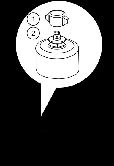
6.1.29.2. RELEASING PRESSURE IN TANK AND RETURN CIRCUIT
1. Remove air breather plastic cap (1) of the pressure relief valve on the hydraulic tank.
2. Press the pressure relief valve (2) to release pressure in the hydraulic tank.
Check the hydraulic oil level, and replace the filter and hydraulic oil.
When removing the high-pressure hoses, check whether the O-ring is damaged. If any damage is found, replace it with a new one.
After replacing the hydraulic oil filter element and cleaning the strainer, oil repairing / replacing the hydraulic units, or dismantling the hydraulic oil piping, bleed the air from the hydraulic oil circuit.
The hydraulic accumulators contain nitrogen gas and hydraulic oil under high pressure; so handle with care to avoid an accident.
Handling of the accumulator Refer to “2.1.20. Handling of Accumulator.”
6.2. OIL, FUEL, COOLANT AND DIESEL EXHAUST FLUID
6.2.1. CAPACITIES OF OIL, FUEL, COOLANT AND DIESEL EXHAUST FLUID
Use products with the following specification or better. Do not mix different brands and qualities of oils.
* See Chapter "6.2.5. Coolant" for mixing ratios according to temperature.
* : Refers to lubricants that are used in filling at the factory
** : See Chapter "6.2.5. Coolant" for mixing ratios according to temperature.
SAE : Society of Automotive Engineers
ISO : International Organization for Standardization
NLGI : National Lubrication Grease Institute
ASTM : American Society of Testing and Material
API : American Petroleum Institute


