24 minute read
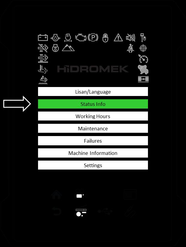
3.4.2. STATUS INFO


To view the status information contents follow these steps:
Touch the “Status Info” button to open the Status Info page.
The below listed pages exists under the Status Info page.
Machine Parameters
Engine Parameters
Optional Attachment Parameters
Opera
Smartlink
Air Conditioner
Touch the title that you would like to display.
To exit from the menu, touch the back key or home key. Also, you can press the back key or home key on the Opera Instrument Panel.
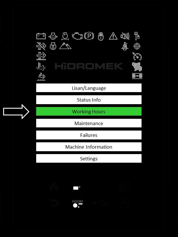
3.4.3. WORKING HOURS
Touch on the “Working Hours” button to open the Working Hours page.
The following Working Hours can be monitored through the control panel. Only trip hours can be changed, others are not adjustable.
To exit from the menu, touch the back key or home key. Also, you can press the back key or home key on the Opera Instrument Panel.
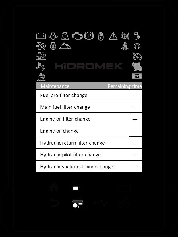
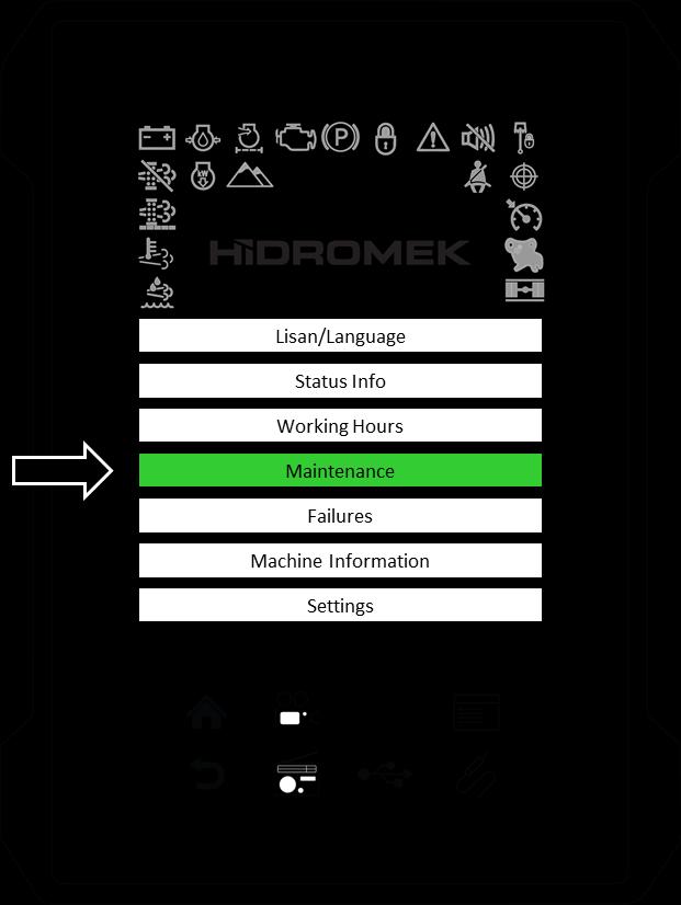
3.4.4. MAINTENANCE
Touch the “Maintenance” button to open the Maintenance page.
The operator can register any maintenance activity that he performed and update the control menu. If it is not updated on time, an alarm buzzes and update message comes on the display.
Before 20 hours to a periodic maintenance, a notification message is displayed on the page. After the maintenance period ends, the system continues displaying the message for another 50 hours.
On the periodic maintenance list; oncoming, current, and elapsed maintenances are displayed in different colors.
Periodic maintenance menu covers various maintenance issues that differ according to the type of the machine.
The below listed periodic maintenance items exists under the maintenance page:
Fuel pre-filter
Main fuel filter
Engine oil filter
Engine oil
Hydraulic return filter
Hydraulic pilot filter
Hydraulic suction strainer
Hydraulic tank breather
Hydraulic oil
Brake filter (wheeled excavator only)
AC filters
Swing unit reduction oil
Travel gearbox oil
Transmission oil (wheeled excavator only)
Front axle oil (wheeled excavator only)
Rear axle oil (wheeled excavator only)
Blow-by oil separator (4JJ1 engine)
DPD filter (Tier4i only)
DEF/AdBlue® filter (Tier4 only)
Engine coolant
Hydraulic breaker filter (optional)
Hydraulic by-pass filter (optional)
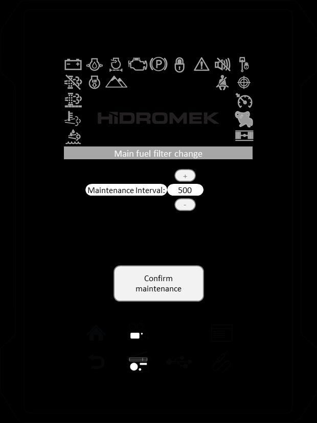
3.4.4.1. Confirming a periodic maintenance
After performing a periodic maintenance activity, touch “Maintenance” button to open the Maintenance page.
Touch maintenance activity that you want to confirm. For example touch "Main fuel filter change".
Touch "Confirm maintenance" button to confirm the maintenance activity.
3.4.4.2. Editing the maintenance interval
You can change each maintenance interval. Touch the maintenance activity that you want to edit. For example touch "Main fuel filter change".
Touch (-) or (+) buttons to change the maintenance interval.
After, touch back or home key to exit page.
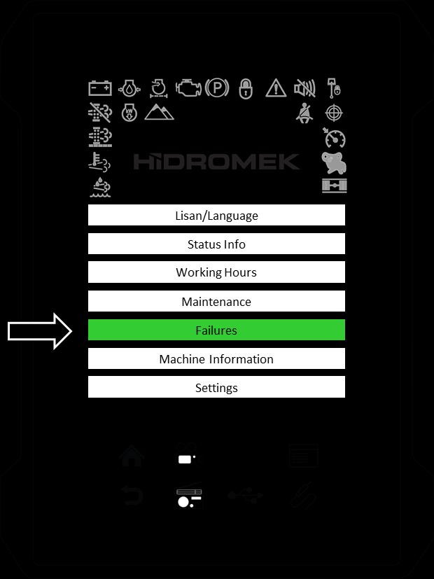
3.4.5. FAILURES
Previously displayed alarms and warning messages and machine working hour of their first appearance is listed in this page.
3.4.6. MACHINE INFORMATION

Installed software versions are displayed on this page.

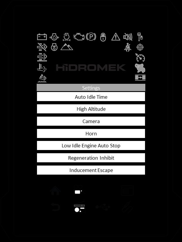
3.4.7. SETTINGS


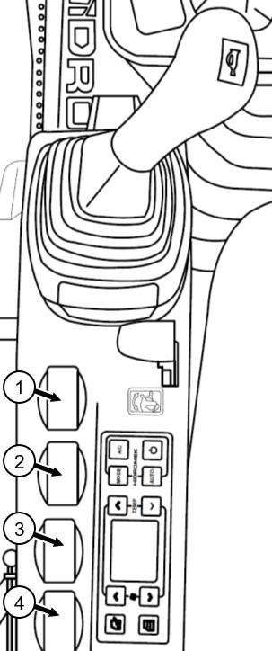
3.4.7.1. Brightness
1. Touch “Settings” sub-menu on the main menu.
2. Touch “Brightness” to enter the Brightness page.
Adjusting the display brightness level:
3. To increase the brightness of the screen, touch and rotate the slider (1) CW.
To decrease the brightness, touch and rotate the slider (1) to CCW.
Brightness level is displayed between 0-100, inside the circular slider.

Turning the display brightness off/on:
4. Touch the "Brightness off" button (2) to turn the display brightness completely off.
5. Touch the screen with minimum 2 fingers to turn the brightness on again.
3.4.7.2. Attachment Settings
As an option, excavators can be equipped with a single or double acting hydraulic piping for attachments on hydraulic line 1 and a double acting low flow hydraulic piping on hydraulic line 2.
WARNING
Be sure that there is no one in the working area during attachment installation and adjustment.
When adjusting the optional attachment, operating values must be set according to the values given by the attachment manufacturer. For any problems about these settings, consult Hidromek Authorized Services or Dealer.
Hydraulic Line 1 (High flow) (L1): This line can be used with attachments such as hydraulic breakers or crushers. It can be adjusted to operate as single or double acting and flow setting can be adjusted to the required value. If the machine is equipped with a pressure relief valve on this line, pressure setting for the attachment can be adjusted.
WARNING
Adjust the position of the 3-way ball valve and set the attachment settings on the instrument panel for an optional attachment or a hydraulic breaker.
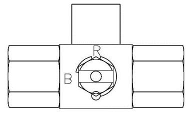
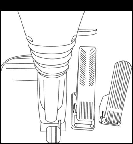
3-way ball valve:
If hydraulic breaker is connected to the hydraulic line, L1 single acting attachment should be selected on the instrument panel and 3-way ball valve should be rotated to "B" Breaker position. If a double acting attachment is connected to this line, L1 double acting attachment should be selected on the instrument panel and 3-way ball valve should be rotated to "R" position. Ensure that 3-way ball valve is rotated to the correct position. Otherwise, the attachment can be damaged.
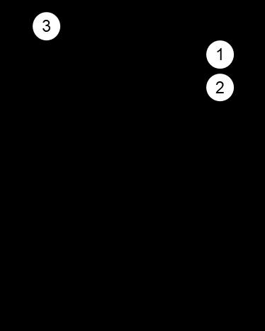
1. Left Proportional Control (Adjustable)
2. Left Joystick Auxiliary Button
3. Horn
Figure. Left Joystick
On machines with electrical type 3-way ball valve: When active attachment is adjusted to a single or double acting attachment, the position of the 3-way ball valve is adjusted automatically according to the active attachment type.
Hydraulic Line 2 (Low flow) (L3): This line is used with attachments such as crushers, shears, polyps, log grapples and for the situations in which an extra hydraulic line is required (especially rotary attachments). It has low pressure and low flow settings.
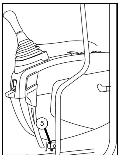
4. Right Proportional Control
5. Null
6. Right Joystick Auxiliary Button(Hydraulic Breaker)

Figure. Right Joystick
7. Double Acting Foot Pedal
Figure. Foot pedal
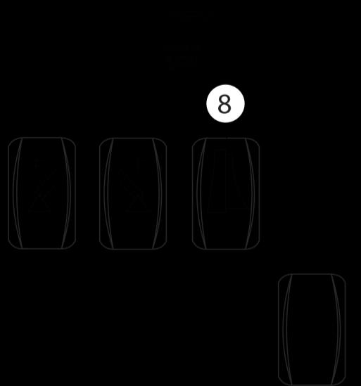
On the instrument panel, 10 different types of attachments can be restored with their configuration.
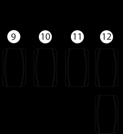
Follow the steps below to configure the Optional Attachments on the Instrument Panel:
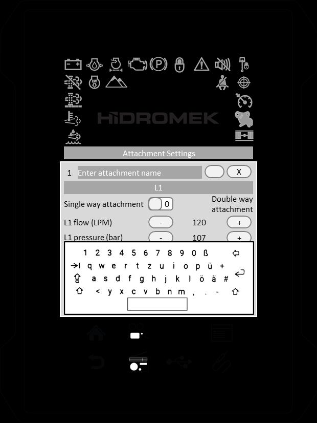
2. Attachment name:
Touch the keyboard button (9) to turn the keyboard on. Touch the attachment name textbox. Using the keyboard, enter a name for the attachment. Touch the keyboard button again to turn the keyboard off.

3.4.7.2.1. Adding new attachment
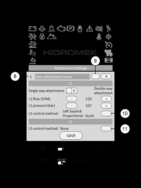
1. Add attachment:
To add new attachment, touch Add button (A). New number (8) will be defined and attachment configuration window will be displayed.
3. Single/double acting selection:
Choose if the attachment is single or double acting using the horizontal scroll bar.
4. Flow adjustment:
Touch (-) or (+) to adjust the flow value of the hydraulic line 1 (L1).
Adjusted flow is kept constant by the control unit, independent from engine speed.
In some cases, if adjusted flow is out of range according to adjusted engine speed, a warning message is displayed on the instrument panel to warn the operator to increase or decrease the engine speed.
Caution
Flow on hydraulic line might be slightly different than adjusted value due to alteration in system parameters like: hydraulic oil temperature, engine speed, etc.
5. Pressure adjustment (optional):
This adjustment can be performed on machines equipped with pressure relief valve.
Touch (-) or (+) to adjust the pressure value of the hydraulic line 1 (L1).
6.
Proportional controllers, buttons on left/right joysticks, and double acting foot pedal can be selected as the control method of the attachments on hydraulic lines. Control method can be adjusted as on/off control, toggle control or proportional control.
On/off control: Hydraulic flow will be supplied to the attachment on optional hydraulic line when selected control is engaged continuously. When selected control is disengaged, hydraulic flow stops.
Toggle control: Hydraulic flow will be supplied continuously to the optional hydraulic line if the selected control is engaged for one time. When selected control is engaged one more time, hydraulic flow stops.
Proportional control: Hydraulic flow rate will be supplied to the optional hydraulic line according to the controller rate. If the controller is moved fully, maximum flow rate will be supplied to the hydraulic line.
6.1.
Touch L1 control method selection button (10).
Choose the proper control method for the hydraulic line 1 from the list below:
-None
- Left Joystick Toggle
- Left Joystick On-Off
- Left Joystick Proportional -Fine
- Left Joystick Proportional -Normal
- Left Joystick Proportional -Quick
- Right Joystick Toggle
- Right Joystick On-Off
- Right Joystick Proportional -Fine
- Right Joystick Proportional -Normal
- Right Joystick Proportional -Quick
- Electrical Proportional Pedal - Toggle
- Electrical Proportional Pedal - On - Off
- Electrical Proportional Pedal - Fine
- Electrical Proportional Pedal - Normal
- Electrical Proportional Pedal - Quick
6.2. L3 control method selection:
Touch L3 control method selection button (11).
Choose the proper control method for the hydraulic line 2 from the list below:
-None
- Left Joystick Toggle
- Left Joystick On-Off
- Left Joystick Proportional -Fine
- Left Joystick Proportional -Normal
- Left Joystick Proportional -Quick
- Right Joystick Toggle
- Right Joystick On-Off
- Right Joystick Proportional -Fine
- Right Joystick Proportional -Normal
- Right Joystick Proportional -Quick
- Electrical Proportional Pedal - Toggle
- Electrical Proportional Pedal - On - Off
- Electrical Proportional Pedal - Fine
- Electrical Proportional Pedal - Normal
- Electrical Proportional Pedal - Quick
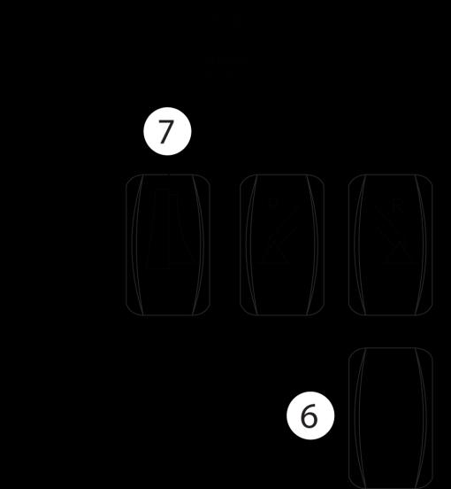
7. Saving the attachment configuration:
Touch save button to save the configuration and close the attachment configuration window.
Touch "X" button on top right corner to quit without saving the configuration.
3.4.7.2.2. Editing the configuration of an attachment
1. Touch attachment window.
2. Touch edit button (B).
Follow the steps in "Adding new attachment" section to configure the attachment.
3.4.7.2.3. Deleting an attachment
1. Touch attachment window.
2. Touch delete button (C).
3.4.7.2.4. Selecting the active attachment
1. To select the active optional attachment, touch the attachment window. Active attachment color becomes green.
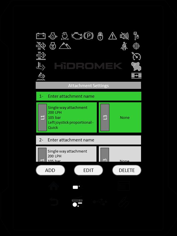
2. Press back key or home key after the attachment is selected.
3. To operate the active attachment, press work button on the Opera Instrument Panel until WORK optional attachment icon appears on the instrument panel.
Optional attachment icon is a hydraulic breaker symbol when single acting attachment is selected and a crusher symbol when double acting attachment is selected. When the optional attachment is selected, the active attachment number will also be displayed near the WORK optional attachment icon.
This symbol shows that the active attachment is a single acting attachment.
The number shows the attachment number which is assigned during creating the attachment under settings page.
This symbol shows that the active attachment is a double acting attachment.
The number shows the attachment number which is assigned during creating the attachment under settings page.
When this optional attachment is selected by the WORK MODE selector key, the control system will automatically adjust the settings for the active attachment. Make sure you have correctly set the operating parameters for the attachment you are going to use and that this attachment is made active from the Create Attachment menu.
There is an alternative shortcut to open the Create Attachment menu: select the optional attachment using the work button and touch the WORK optional attachment icon on the instrument panel.
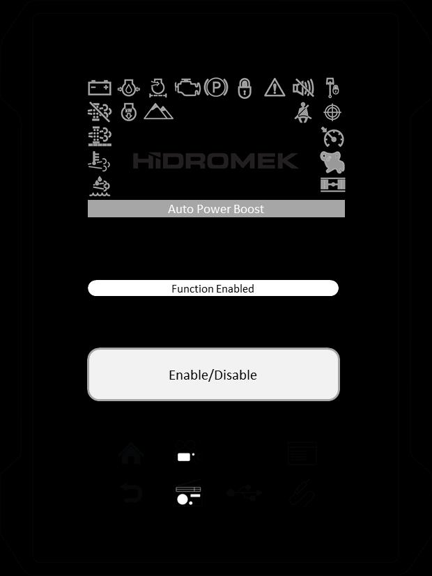
3.4.7.3. Auto Power Boost
If this function is on, power boost will be activated automaticallydepending on hydraulic pressure. Auto Power boost function can be enabled or disabled through this setting.
3.4.7.4. Travel Power Boost (If exists)
If this function is enabled; when the machine starts traveling, the power boost will be activated. Travel Power boost function can be enabled or disabled through this setting.
1. Touch “Settings” sub-menu on the main menu.
2. Touch the “Auto Power Boost" to enter the Auto Power boost page.
3. Touch the Enable/Disable button to enable or disable the function.
The status of the function is indicated above the change button as "Function Enabled" or "Function Disabled".
1.Touch the“Settings” sub-menu on the main menu.

2. Touch the “Travel Power Boost” to enter the Travel Power boost page.
3. Touch the Enable/Disable button to enable or disable the function.
The status of the function is indicated above the change button as "Function Enabled" or "Function Disabled".
3.4.7.5. Travel Speed Up
If the machine starts traveling when the "Travel Speed Up Function" is "ON", diesel engine speed is increased automatically by the control unit to enable higher speed to travel. This function can be enabled or disabled through this setting.
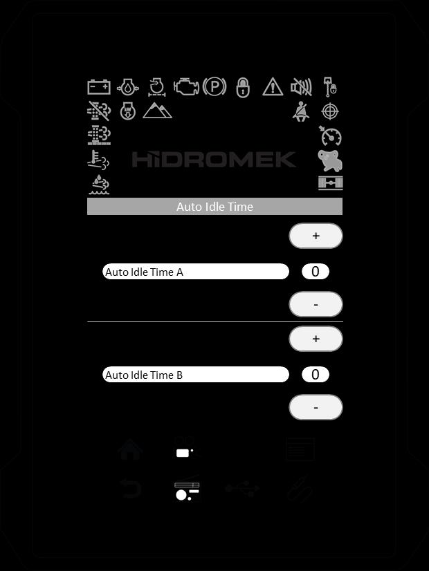
3.4.7.6. Auto Idle Time
For the auto idle function to take effect, auto idle must be activated. To activate or deactivate the auto idle press the Auto Idle On-Off Switch on the Opera Instrument Panel. When auto idle is activated, the auto idle symbol comes on the instrument panel.
Proceed with the following steps to set Auto Idle Times:
1.Touch the“Settings” sub-menu on the main menu.

2. Touch the “Travel Speed Up” to enter the Travel Speed Up page.
3. Touch the Enable/Disable button to enable or disable the function.
The status of the function is indicated above the change button as "Function Enabled" or "Function Disabled".
1.Touch the“Settings” sub-menu on the main menu. Touch the “Auto Idle Time” to view preset settings.
2. There are two Auto Idle Times. If attachments are not controlled, engine speed will decrease to 1200 rpm after the selected Auto Idle Time A (Auto Idle) in seconds. If attachments are not controlled for a further time of Auto Idle Time B (Idle) in seconds, engine speed will be decreased to idle speed.
Auto Idle Time A can be set at any value between 4 seconds to 30 seconds.
Touch (-) or (+) to adjust the Auto Idle Time A.
Auto Idle Time B can be set at any value between 20 seconds to 250 seconds.
Touch (-) or (+) to adjust the Auto Idle Time B.
3.4.7.7. High Altitude
High altitude function can be enabled or disabled and high altitude operation percentage can be adjusted through this setting.
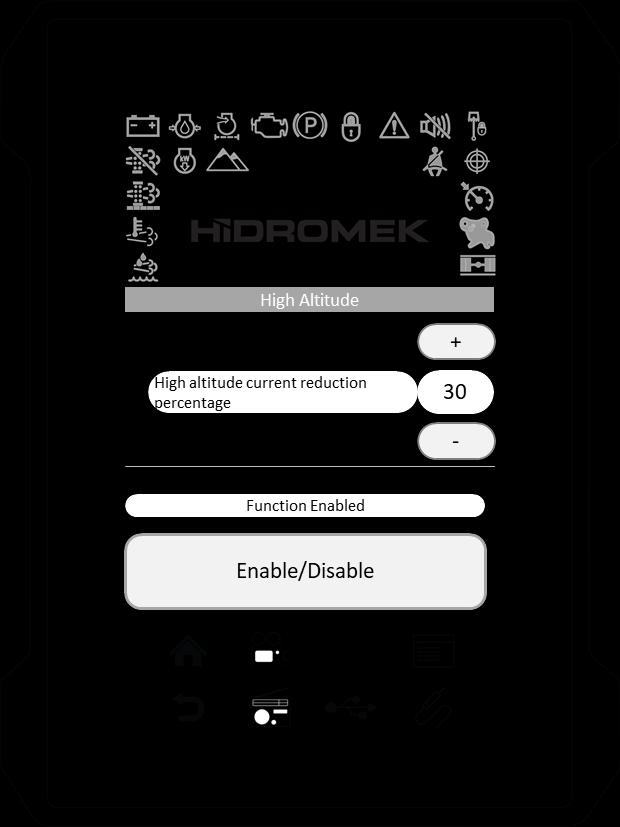
This function can be enabled while working on high altitudes in order to eliminate engine stall and black smoke emission. High Altitude Operation Percentage should be adjusted to proper level according to operation altitude.
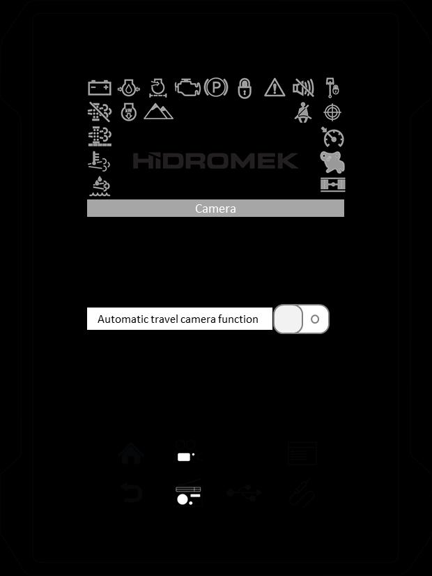
3.4.7.8. Camera
Travel camera can be activated or deactivated through this setting.
When this function is activated, the default camera will be displayed automatically when the machine starts traveling.
1. Touch “Settings” sub-menu on the main menu.
2. Touch “High Altitude” to enter the High Altitude page.
3. Touch the Enable/Disable button to enable or disable the function.
The status of the function is indicated above the change button as "Function Enabled" or "Function Disabled". When this function is enabled, high altitude function indicator will display green on the instrument panel.
1.Touch the“Settings” sub-menu on the main menu.
2. Touch the “Camera” to enter the Camera page. It is indicated on the on/off button if the Automatic travel camera function is on or off with numbers "1", "0", respectively.
3. Touch the button to enable the function.
4. Touch the button to disable the function.
High altitude function indicator
High Altitude Operation Percentage:
High Altitude Operation percentage can be adjusted using (-) and (+) buttons.
3.4.7.9. Horn
Starting Horn, Travel Horn (if exists) and Swing Horn (if exists) functions can be enabled or disabled through this setting.
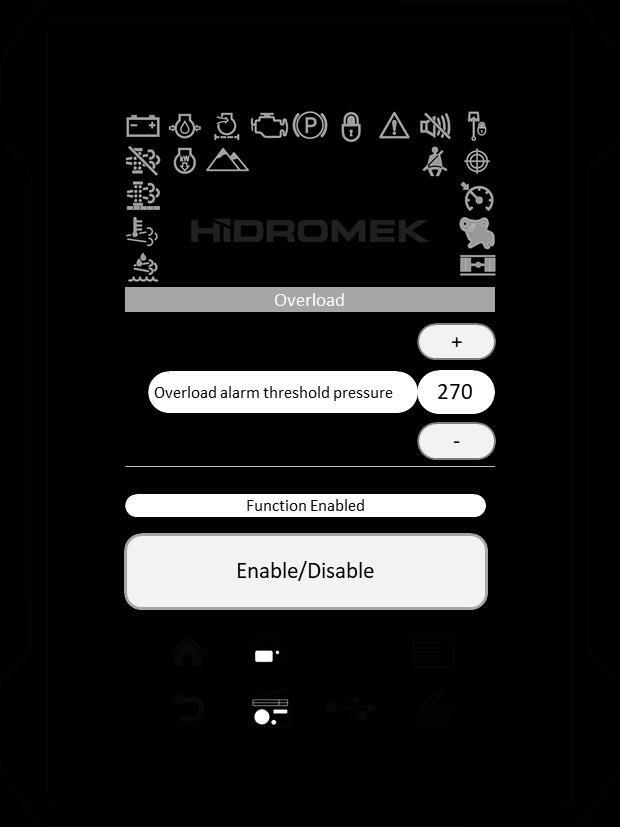
3.4.7.10. Overload (If exists)
Overload Function can be enabled or disabled and Overload Alarm Threshold Pressure (bar) can be adjusted through this setting.
When the lifting pressure of the boom cylinders reaches the adjusted Overload Alarm Threshold Pressure, a warning message appears on the instrument panel and buzzer sounds.
1. Touch “Settings” sub-menu on the main menu.
2. Touch “Horn” to enter the Horn page.
There are three different kind of horn settings.
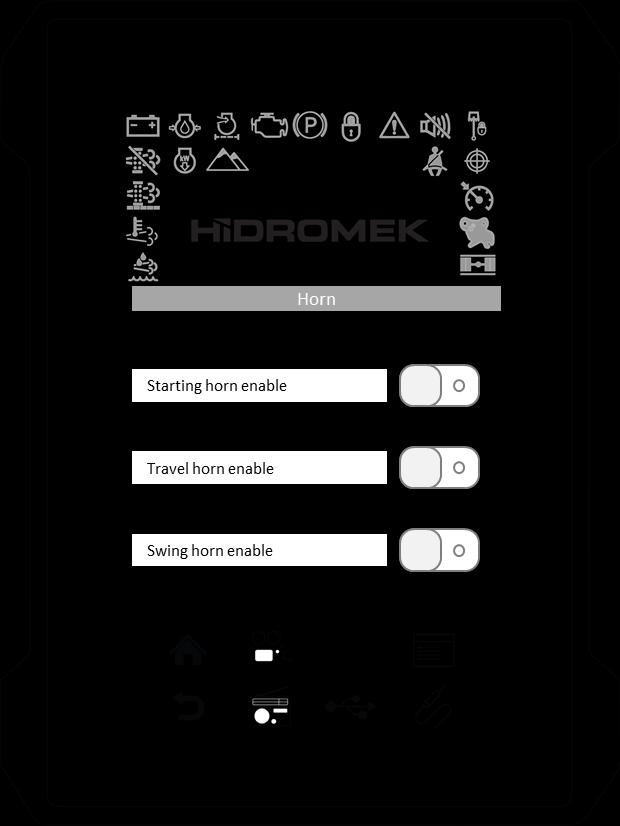
If the Starting Horn is enabled, horn sounds when the starting key turned to ON position.
If the Travel Horn is enabled, horn sounds when machine travels.
If Swing Horn is enabled, horn sounds when upper chassis swings.
To enable/disable the horn, use the sliding on/off button near each function.
It is indicated on the on/off button if the function is on or off with numbers "1", "0", respectively.
3. Touch the button to enable the function.
4. Touch the button to disable the function.
1. Touch “Settings” sub-menu on the main menu.
2. Touch “Overload” to enter the Overload page.
3. Touch the Enable/Disable button to enable or disable the function.
The status of the function is indicated above the change button as "Function Enabled" or "Function Disabled".
Overload Alarm Threshold Pressure:
Overload Alarm Threshold Pressure can be adjusted using (-) and (+) buttons.
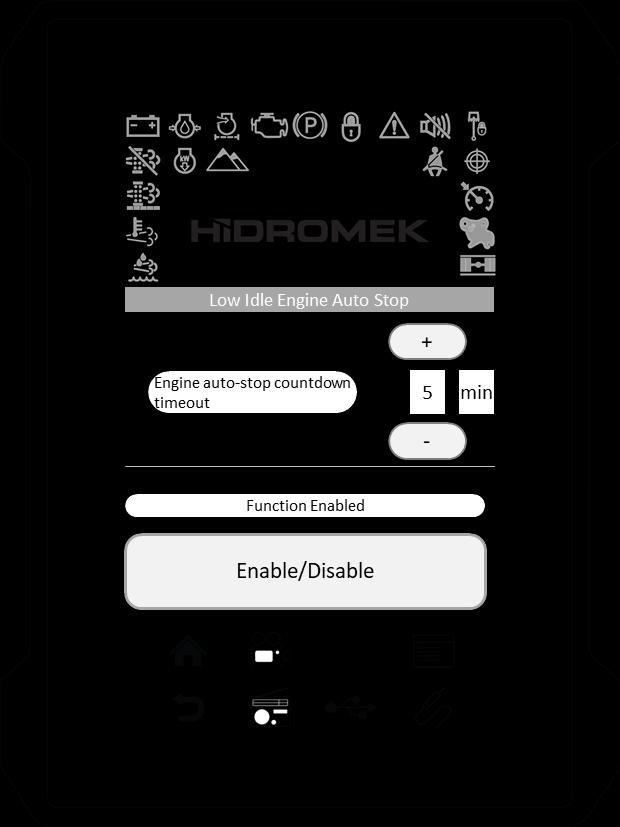
3.4.7.11. Low Idle Engine Auto Stop
Low Idle Engine Auto Stop function can be enabled or disabled and Engine auto-stop countdown timeout can be adjusted through this setting.
1. Touch “Settings” sub-menu on the main menu.
2. Touch “Low Idle Engine Auto Stop” to enter the Low Idle Engine Auto Stop page.
3. Touch the Enable/Disable button to enable or disable the function.
The status of the function is indicated above the change button as "Function Enabled" or "Function Disabled".
Engine auto-stop countdown timeout: Engine auto-stop countdown timeout can be adjusted using (-) and (+) buttons.
3.4.7.12. Regeneration Inhibit
Purge Inhibit function can be enabled or disabled through this setting.
1. Touch “Settings” sub-menu on the main menu.

2. Touch “Regeneration Inhibit” to enter the Regeneration Inhibit page.
3. Touch the Enable/Disable button to enable or disable the function.
The status of the function is indicated above the change button as "Function Enabled" or "Function Disabled".
WARNING
Operating the engine while Purge Inhibit function is enabled, the aftertreatment functioning stops and will cause severe damage to the exhaust system components: DPD, DOC, and SCR.
Enable the Purge Inhibit function only in dangerous working conditions where exhaust system may cause a fire or an explosion.
After operating the machine while this function is enabled, move the machine to a safe place and purge Urea SCR System. For more information refer to Chapter 4.5. Urea Selective Catalytic Reduction (SCR) System.
If automatic or manual purging has not been completed within a predetermined amount of time due to purging being inhibited, the engine warning light will be illuminated and purging will become impossible, so do not inhibit purging unless necessary.
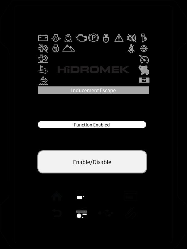
3.4.7.13. Inducement Escape
If automatic and manual Urea SCR Purging is not completed within a specific period, Engine Control Unit limits the engine speed and torque.
In this situation, if an emergency condition is occurred and it is necessary to move the machine immediately, then this limitation can be cancelled for a short time using this function.
Inducement Escape function can be enabled through this setting for a pre-determined duration. After the time elapsed, it is disabled automatically by the control unit.
1. Touch “Settings” sub-menu on the main menu.
2. Touch “Inducement Escape” to enter the Inducement Escape page.
3. Touch the Enable/Disable button to enable or disable the function.
The status of the function is indicated above the change button as "Function Enabled" or "Function Disabled".
Warning
Enable Inducement Escape function only in emergency situations to move the machine out of the danger zone. Do not operate attachments in this mode. Consult HIDROMEK AUTHORIZED SERVICE to have the problem fixed as soon as possible.
3.5. MEDIA
When the media key on the opera instrument panel is pressed, media page is displayed on the side panel.
There are 3 different media pages in the Instrument Panel: Radio, USB and AUX. Each time the media key is pressed, it switches between these pages.
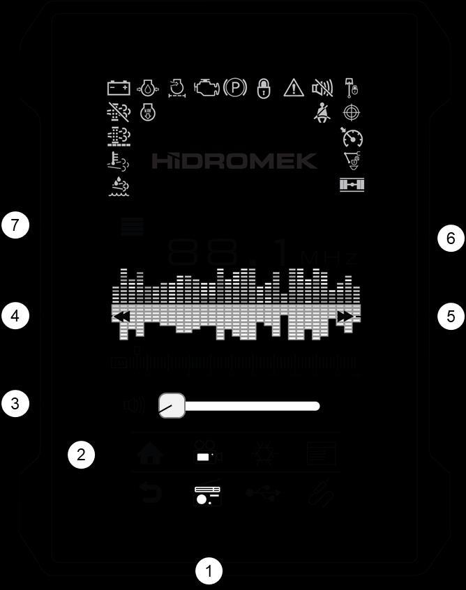
3.5.1. RADIO
Radio page can be opened by media key or by touching the radio key on the instrument panel.
Saving a radio station to favorite radio stations list:
1. Touch radio key and turn the radio on.
2. Find the radio frequency using down/up seek keys (4 and 5).
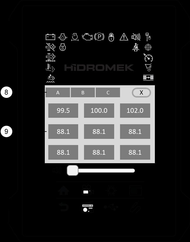
3. Touch favorite radio stations key (7) to open favorite radio station window.
There are 3 groups (A, B, C) and in each group there are 9 favorite radio stations.
4. Touch the favorite radio station button at least two seconds to save the current radio frequency to the favorite station.
Playing a radio station from favorite radio stations list:
1. Touch radio key (1) and turn the radio on.
2. Touch favorite radio stations key (7) to open favorite radio station window.
3. Touch the favorite radio station button that you would like to listen. The radio station you selected starts to play and the color of the button becomes green.
1. USB key
2. Volume control

3. Mute key
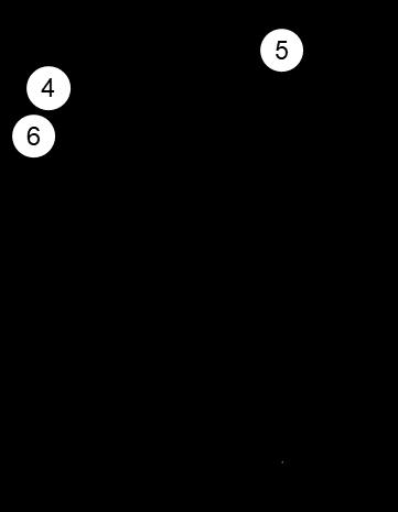
4. Previous song key
5. Play key
6. Stop key
7. Next song key
8. Progress bar
9. USB file/folder list
Connect a USB device through USB input if you would like to listen to MP3 file in a USB device.
If a USB device is inserted, MP3 files in a USB device will be playing after setting the instrument panel to USB mode by pressing USB key (1) on the instrument panel or the media key on the opera instrument panel.
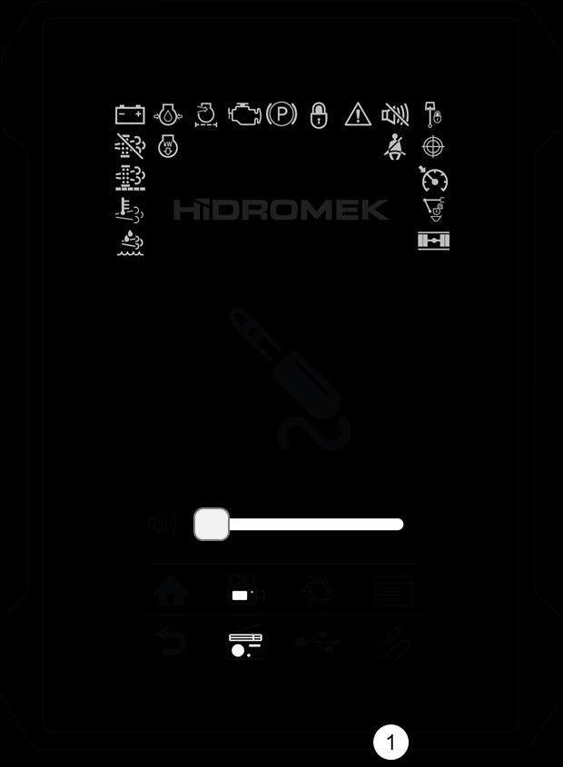
If you want to listen to music of an external audio device, connect an external audio device through AUX input using a suitable cable.
Set the instrument panel to AUX mode by pressing AUX key (1) on the instrument panel or press the media key on the opera instrument panel.
If audio file of audio device is playing, you can listen to music through audio speakers inside the operator's cab.
Sound level can be adjusted in the range from 0 to 100. If the sound level is not sufficient even the volume is increased, check the sound level of connected external device.

1.
Engine Start / Stop Button
This button is used to start and to stop the engine. After turning the starting switch "ON", keep this button pressed to start the engine. If you press this button again while the engine is running, the engine will be stopped.
2.
Buzzer Mute (Volume OFF) Button
If some failure occurs on the machine, a buzzer warns the operator. When this key is pressed, the buzzer is temporarily muted.
3. Axle lock switch
This switch is used to lock and unlock the front axle. When it is locked, axle can’t oscillate. When it is unlocked, axle oscillates according to the ground structure. At position ON, oscillation cylinders are at unlocked position and axle lock indicator light is off.
4. Camera Key temperature values are obtained. This is an automatic function of the engine control system; the operator will have no control on it unless this function cancelled manually.
This key is used to display the camera on the instrument panel.
Press once to display the camera. Press it again to display the next camera (if exists). Press it for the third time to display the next camera (if exists).
Press Home Key or Back Key to exit.
After the engine coolant and hydraulic oil warmed up adequately, or 15 minutes elapsed after the engine start, then the engine speed will change according to the selected power mode and the position of the speed control dial.
6. Home Key
While inside the menu, press this key to return to the main page.
7. Back (Cancel) Key
Press this key to exit from the current menu or to return to the previous menu.
8. Power Mode Selecting Switch
Press to select among available power modes.
For more information refer to Instrument Panel section.
9. Low / High Travel Speed Selection Button
This button is used to select low or high travel speed. On crawler machines Low Travel mode is default whereas the rubber wheeled machines will start with High Speed travel as a default mode.
5.
"Auto Idle On-Off / Auto Warm Up Cancellation" Key
Cancel auto warm up function, or either turn the auto idle function on or off by pressing this key.
Auto idle on-off steps: On the main display by pressing the auto idle button, this function will be switched on or off.
Auto idle: There are two predefined levels for Auto-Idle activation. These Auto Idle Activation Levels can be set by the operator between (3-30 second) for the LEVEL-1 and between (20-250 seconds) for the LEVEL-2. When the Level-1 period has elapsed with no joystick control, the engine speed will be decreased to 1200 rpm. If attachments are not controlled for a further Level-2 period, the engine speed will be decreased to IDLE speed.
If the joysticks are operated in the meantime, then the engine speed will be recovered at the set value by the operator before the auto-idle activation took effect.
Auto warm up cancellation: Auto warm up function should only be canceled in an emergency situations. This can be done by pressing the auto idle cancellation button for 3 seconds on the main display.
Auto warm up: If engine coolant temperature is lower than 30 ˚C and/or hydraulic oil temperature is below 0 ˚C when the engine has been started, the engine speed will be gradually increased to 1200 rpm and auto warm up function will be switched on for a period of maximum 15 minutes until normal
10. Work Mode Selecting Switch
Press to select among available work modes. For more information refer to Instrument Panel section.
11. One Touch Idle Switch
If "one touch idle" switch is pressed on the instrument panel when auto-idle function is turned off, auto-idle function turns on and if the attachments are not controlled by that time machine sets the engine speed to 980 rpm without waiting adjusted auto-idle times. After the attachments are controlled, pre-adjusted settings are applied.
12. Cruise function switch
CR function sets the engine RPM during traveling. This function is available only on travel mode. Refer to "Chapter 4.11. Cruise Funciton" for more information about how to use this function.
13. Media Key
When this key is pressed, media page is displayed on the side panel.
Each time this key is pressed, it switches the media page between Radio, USB and AUX.
14. SRC key
Each time this key is pressed, it switches the radio to the next favorite radio station. Favorite radio stations have 3 groups (A, B, C). This key only switches between the radio stations in the active group.
15. Radio Down Tune Seek / Previous Song Button
To automaticallyselect a radio station, momentarily press the DOWN TUNE SEEK button to search for the closest radio station.
To manually select a radio station, press the DOWN Tuning button for longer than 3 seconds. The radio frequency will move down step by step each time you press button.
Also this button is used to select the previous song when the music player is in USB mode. Each time the button is pressed, the file number is decreased.
16.
To automaticallyselect a radio station, momentarily press the "UP TUNE SEEK" button to search for the closest radio station.
To manually select a radio station, press the UP Tuning button for longer than 3 seconds. The radio frequency will move up step by step each time you press the button.
Also this button is used to select next song when the music player is in USB mode. Each time the button is pressed, the file number is increased.
17.
Working Lamps Switch (Boom)
Press to turn the working lamps on the boom on. Press again to turn the working lamps on the boom off.
18.
Beacon Lamp Key
It functions when the starting switch is turned ON. When you press this key, rotary lamp at the top of the operator's cabin lights up together with the light on the key. When the key is pressed again, rotary lamp and key light both turn off.
19.
Press once to turn working lamps on the front side of the operator's cab on.
Press again to turn working lamps on the rear side of the operator's cab on. All of the working lamps on the front side and the rear side of the operator's cab turns on at the same time.
Press third time to turn all lights off.
20. Volume Adjust and Music Player ON/OFF Button
Press the knob to turn on/off the music player. Turning the knob increases or decreases the volume. Turn the knob to the right to increase the volume, turn it to the left to decrease the volume.
21. Headlights Switch
This switch turns on/off the parking lamps and low beam headlights.
Press once to turn on the parking lamps. Press again to turn on the low beam lights. Press third time to turn the lights off.
22. INFO (Information) Key
If the engine is running, INFO function is not active. INFO function is used to receive information about the functions of other keys on the machine.
When INFO key is pressed once, INFO function activates, the functions of other keys on the machine are temporarily disabled and the lamp on the key lights up. While the INFO key is active, press the key of any function which you need to know, information about the function of that key will be displayed on the side panel.
When you press INFO key again, the function will be disabled and the lamp on the key turns off
23. Throttle Control Dial
The dial controls the engine speed manually. Turn the dial to the right to increase the engine speed; turn the dial to the left to reduce the speed.
Warning
Do not suddenly shut off the engine when operating at high speed. First, rotate dial to low speed to allow the engine and turbocharger speeds to stabilize, and then shut it off.
24. Menu Search and Confirmation Knob
Press this knob continuously for 3 seconds to enter the menu.
When you enter the menu of instrument panel, by turning this knob to right or left, you can surf among the titles of the menu.
After deciding on the title you want to select, press this knob to confirm.
Usb Function
Connect a USB device through USB input if you want to listen to MP3 file in a USB device.
If a USB device is inserted, MP3 files in a USB device will be playing after setting the instrument panel to USB mode by pressing media key on the instrument panel or the media key on the opera instrument panel.
Usb Specifications
1) The essential features of the device are as follows :
- Compatible with FAT, FAT12, FAT16 and FAT32 file systems.
- 200 Directories and 999 Files can be introduced in the USB device.
- TAG (ID3) file information of types V1.1, V2.2 and V2.3 can be displayed.
2) Only 20 characters can be displayed.
3) MULTI-CARD READER can not be supported.
4) Compatible with USB 1.1 and USB 2.0 standards.
5) USB device will be subjected to vibrations when it is connected. Disconnect the USB device to avoid any harm if it is not used.
Aux Function
If you want to listen to music of an external audio device, connect an external audio device through AUX input using a suitable cable.
Set the instrument panel to AUX mode by pressing media key on the instrument panel or press the media key on the opera instrument panel.
If audio file of audio device is playing, you can listen to music through car audio speakers.
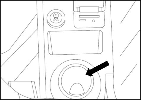
3.8. EXTERNAL SOCKET (12 V)
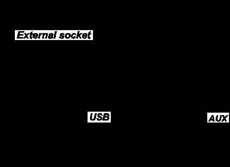
There is an external electrical socket on the right hand side console.
WARNING
Do not connect any device that uses energymore than 100 W.
3.9.
Starter Key
Starter key is used to start or stop the engine.
"OFF" position
The starter key can only be inserted or pulled out in the OFF position. In this position the electric circuit to the system is cut-off.
"ON" position
The electric circuit to the engine is ON. Leave the key in this position after starting.
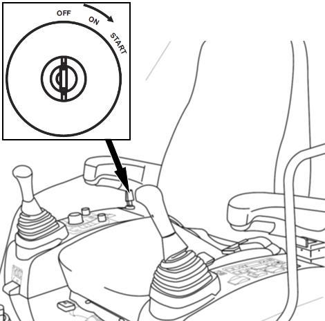
"START" position
Used to start the engine. Release the key immediately after starting. The key returns to "ON" position.
It is mounted on the front console. It shows total operating hour of the machine.
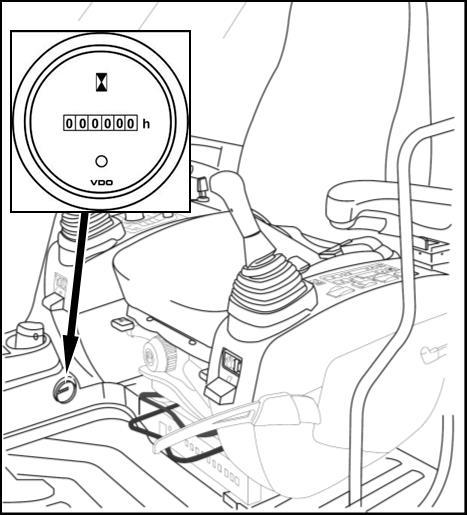
In addition to hour meter, it is possible to see this value as well as the working hours, attachment hours and travel hours on the “Operating Hours” menu of the control panel.
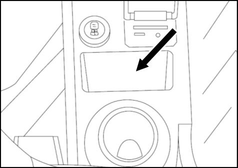
3.12.
Small objects like glasses, wallets etc. can be stored in this place. Also devices may 3.13.
There is a storage box under the right armrest
1. Quick coupling switch (optional)
For more information on using the switch refer to "Chapter 8.8. Quick Coupling Attachment".
4. Front and Rear Working Lamps (optional)
Turns on the working lamps that mounted on the top of the operator's cab. Press once to turn on the front working lamps. Press again to turn on front and rear working lamps together. Front and rear working lamps are optional equipment.
2. Purge switch
Press to either start or pause the manual purging process.
See "Chapter 4.5. Urea Selective Catalytic Reduction (SCR) System” for detailed information.
5. Engine emergency stop switch
Use this switch if the engine can not be shut OFF and only in case of an emergency situation to stop the engine immediately.
6. Swing Lock Switch
Press it to apply swing lock. For more information refer to Chapter 3.23. "Swing Lock".
7. Front Dozer Enabling Switch
Press the upper side of the switch to enable and lower side of the switch to disable the dozer.
8. Rear Dozer Enabling Switch
Press the upper side of the switch to enable and lower side of the switch to disable the dozer.
9. Front Left Outrigger Enabling Switch
Press the upper side of the switch to enable and lower side of the switch to disable the outrigger.
10. Front Right Outrigger Enabling Switch
Press the upper side of the switch to enable and lower side of the switch to disable the outrigger.
11. Rear Left Outrigger Enabling Switch
Press the upper side of the switch to enable and lower side of the switch to disable the outrigger.
12. Rear Right Outrigger Enabling Switch
Press the upper side of the switch to enable and lower side of the switch to disable the outrigger.
3.15. DOZER BLADE AND OUTRIGGER CONTROL LEVER
3.15.1. CONTROL LEVER ON MACHINES WITH ELECTRICAL-TYPE CENTER JOINT

This lever is located on the right hand side console near the right hand side control lever
To move the stabilizers down, push the lever forward
To move the stabilizers up, pull the lever backward. Outriggers and dozer blade of which their enabling switches are activated, will move with the control of the dozer blade and outrigger control lever.
3.16. STEERING
It is used to change the traveling direction of the machine.
3.16.1. STEERING COLUMN
It has Steering Wheel, Indicator Lights, Speed Selection Switch, and Multi-Function Lever, Mode Selection Switch and "Hazard Warning Light" Switch on it.
STEERING WHEEL HEIGHT ADJUSTMENT
There is an adjusting lever (1) at the right hand side of the steering column Pull the lever backward to unlock. Adjust the telescopic height and push the lever forward to lock at desired position.
STEERING WHEEL ANGLE ADJUSTMENT
To tilt the steering column toward operator or toward windshield, push the pedal (2) and move the steering wheel in forward-backward direction.


