52 minute read
6.5.7. HYDRAULIC OIL LEVEL CHECK


Warning
Add fuel or oil in a well-ventilated area. Before adding fuel or oil, stop the engine, keep away all sources of fire and do not smoke.. Wipe up spilled fuel or oil immediately. Tighten the caps on containers for fuel or oil securely.
1. Park the machine on a hard and level ground.
2. Position the machine as follows to check hydraulic oil level:

Extend the bucket cylinder completely, and retract the arm cylinder completely.

Lower the boom to the ground completely.
Stop the engine.
Turn starter switch to ON position.
Move the left and right control levers in full course in all directions to relieve internal pressure in hydraulic circuits.
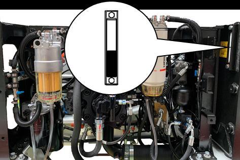
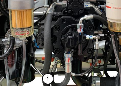
3. Open the pump door located at the right hand side of the machine. Hydraulic oil level gauge is located on the front wall of pump compartment. Check the hydraulic oil level through the gauge.
If the oil level is in the center of the gauge, it is correct.
If the level is low, open the cover of the hydraulic tank and add hydraulic oil.
Hydraulic oil Refer to "Chapter 6.2. Oil, Fuel, Coolant and Diesel Exhaust Fluid".

Important
Be careful not to refill the hydraulic oil above the correct level. If the current oil level exceeds the required oil level, the hydraulic oil may overflow or cause damage to the hydraulic circuit.
6.5.8. ELECTRIC WIRE CHECK
WARNING
If the fuses are repeatedly blown or the traces of short circuit are found, find the cause and repair it
Check the fuses or electric wires for damaged or short circuit. Check the terminals for looseness. Tighten the loosened terminal securely. Especially, inspect the wiring to and from the following components:
Battery
Start motor
Alternator
Contact Hidromek Authorized Dealer or Service station in case of a problem.
6.5.9. CLEANING THE FILTER OF HYDRAULIC TANK BREATHER
In dusty working environments, the dust will be collected around the hydraulic tank breather.
Clean the surrounding of the hydraulic tank breather regularly so air flow of the hydraulic tank will not be blocked.
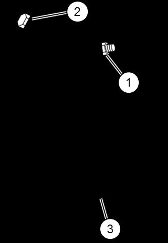
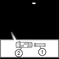
6.5.10. CHECKING AND CHANGING THE BUCKET TEETH
Change the bucket teeth before the adaptors wear away.
When changing the bucket teeth, always lower the bucket to the ground, position it to the safest posture for working, stop the engine and lock the safety locking system securely.
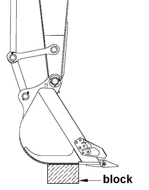
Place a block under the bucket, then lower the bucket keeping it horizontal. Stop the engine and lock the safety locking system.
WARNING
Before removing locking pins, always wear eye protection!
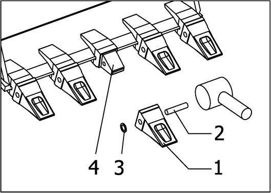
Drive out pin (2) using a hammer and punch. Be careful not to damage the lock washer (3).
Use a round bar with a smaller diameter than the pin as a punch.
Clean the surface of adapter (4), insert a new lock washer (3) in the correct place, and install a new tooth (1).
Drive pin (2) into the pin groove, through lock washer (3) until the pin is flush with the teeth.
6.5.11. FAN BELT
Fan belt has the function of transferring the engine rotational force to the auxiliary equipment and enabling operation of each mechanism.
When replacing the fan belt, it is recommended to use the "Hidromek genuine parts".
If a low quality and unapproved belt is used, it may cause problems like abnormal engine noise, halt of the engine unexpectedly and insufficient battery charging because of rapid belt wear or belt rupture.
Too loose or too tight V-belts will cause problems like a squeaking noise, engine overheating, insufficient battery charging, alternator malfunction and water pump malfunction. The tension of the belts must be adjusted correctly.
Caution
If the fan belt is too tight, the alternator bearings may be damaged, causing an engine failure or an accident.
If the fan belt is too loose, it may slip or be damaged which will cause abnormal noises and vibrations, overheating, or charging failures those may result in an engine failure or an accident.
6.5.11.1. CHECKING FAN BELT TENSION
Follow the procedure below to inspect the fan belt:
1) Press the center of the belt (between the alternator pulley and idle pulley) with a force of 98 N (approx. 10 kgf) and measure the maximum deflection. If the belt tension is correct maximum deflection should be in accordance with the table below:
Engine Max. deflection Vibration frequency
Isuzu 4HK1 6 - 8 mm 210 Hz
2) Inspect the belts. If necessary re-adjust the tightness. Replace them if any damage is found.
Warning
For safety, before inspecting fan belt, make sure that the engine is stopped and is not going to be operated during the inspection. Remove the starter key from the machine. Hang a "DO NOT OPERATE" sign on the front panel of the operator's cab.
Warning
Before performing anycontrols, check if the engine is stopped. Otherwise your hands, clothes, hair or feet may be caught in the rotating parts or linkages of the engine and it mayresult in a serious damage or even death.
If any of the V-belts is found to be damaged, have it replaced immediately at your HIDROMEK
Authorized Service or Dealer. Damaged belts are detrimental to the engine, especially when they are broken.
Keep the V-belts free of oil and grease. Contact with these substances can cause the belts to slip and may shorten their service life.
When replacement is necessary, replace both Vbelts at the same time.
6.5.11.2. ADJUSTING FAN BELT TENSION
Adjust fan belt tension when the belt slackness is greater than specified amount and when the belts are replaced. Belt tension adjustment is made by pivoting the alternator on the alternator mounting bolt.
1. Loosen mounting bolt (1) of alternator and the locknuts (3).
2. Adjust the belt tension with adjusting bolts (2) of the alternator and secure the alternator within specified range.
3. Tighten the loosened mounting bolt (1) and the locknuts (3) securely.
Tightening torques
4. After the adjustment, operate the engine 5 minutes at low idle speed and recheck the belt tension. If necessary re-adjust the belt tension.
Caution
Belt tension may vary slightly after the alternator is fixed. Therefore, recheck the belt tension after tightening the bolts.
Caution
If any belt is found cracked or damaged as a result of inspection, it must be replaced as soon as possible. Have the replacement done by your dealer as it involves disassembly of the engine.
Caution
Initial stretching takes place in any new belt after installation. Also, to fit the belt well in the pulley groove, adjust the belt following the adjustment procedure below regardless of new installation or tension adjustment. Adjust the belt alignment and belt tension in accordance with the specified procedure. Start the engine and allow it to idle for at least 5 minutes in order to run-in the belt. Stop the engine, and again adjust the belt tension to the standard value.
1. Lock nut
2. Adjusting bolt
3. Mounting bolt
Isuzu 4HK1
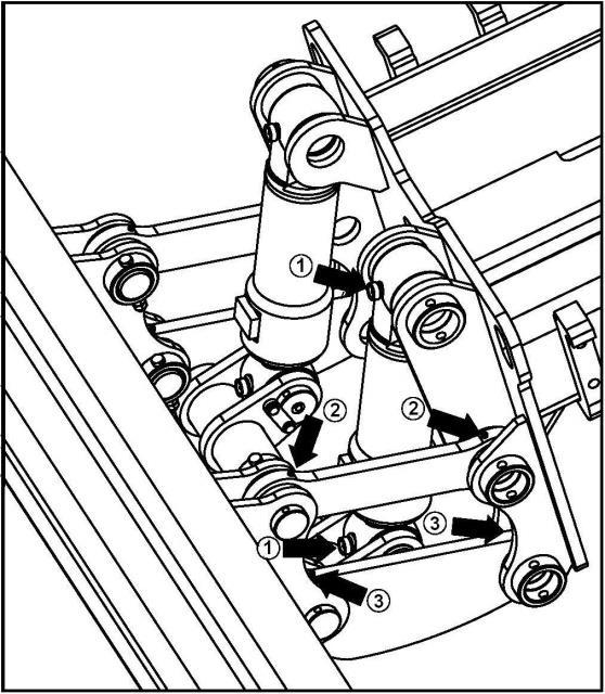
6.5.12. GREASING ATTACHMENT PINS
1) In manual refilling, lower the attachment to the ground as illustrated, and stop the engine.
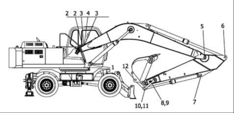
2) Refill the grease through the grease fittings using a hand or power grease gun.
3) After refilling grease, clean off the overflow grease.
Caution
If the machine has worked in water, immediately refill new grease to the submerged parts like the bucket pins to remove the old grease, regardless of the grease refilling cycle time after the work.
(1) Boom cylinder mounting pin (2 points)
(8) Connecting pin of arm and bucket (2 points)

(9) Connecting pin of arm and link (2 Points)
(2) Boom mounting pin (3 points)
(3) Boom cylinder rod end pin (2 points)
(4) Arm cylinder mounting pin (1 point)
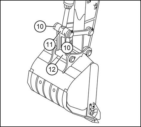
(10) Connecting pin of connecting rod and link (2 points)
(11) Bucket cylinder rod end pin (1 point)
(12) Connecting pin of bucket and connecting rod (1 point)
If machine is equipped with optional automatic greasing system, points shown in figure below will be greased automatically:
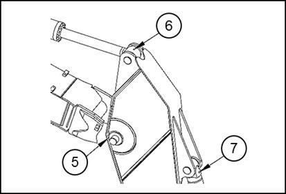
(5) Connecting pin of boom and arm (2 points)
(6) Arm cylinder rod end pin (1 point)
(7) Bucket cylinder mounting pin (1 point)
6.5.13. CHECK TIRES FOR CORRECT PRESSURE AND DAMAGE
Check all tires to make sure that they are properly inflated and are not damaged. Make sure that all excess mud, stone, etc. has been removed from the tires
6.5.14. CHECK THE BRAKE
Always check service brake performance before starting.
Emergency Braking: At a service brake failure, the braking effect of the hydrostatic drive is also additionally acting. This braking is not adjustable and cannot be influenced by the operator.
BRAKE SYSTEM TEST PROCEDURE
• Start the engine and select power mode “P”.
• Run the engine for about 5-10 minutes to warmup and stop the engine.
• Turn the ignition key to “ON” position without starting engine.
• "Brake pressure low" warning light must not come ON. In this mode press the brake pedal fully and release. Repeat the process several times with some waiting periods between pedal operations. Pedal must be pressed at least 3 times before the "brake pressure low" warning light comes ON. If not, the accumulator may be faulty. Do not move the machine and call Hidromek Authorized Service for help.

Warning
Do not operate a machine whose brakes are faulty. All maintenance and repair works on the brake system must be performed only by an authorized Hidromek service.
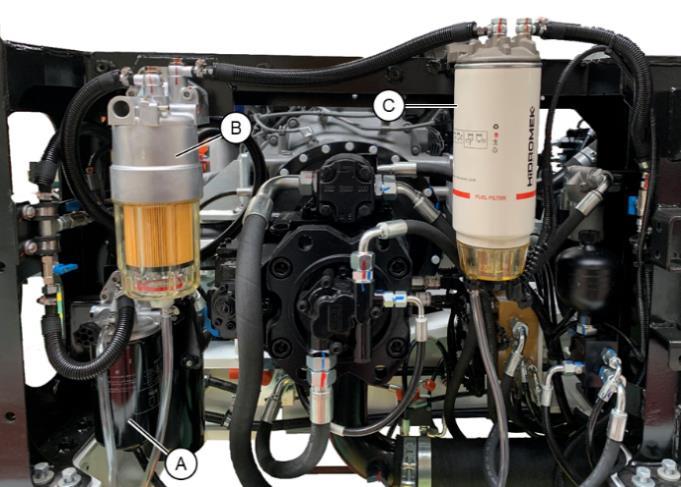
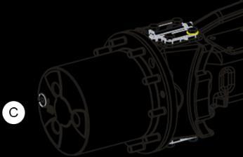
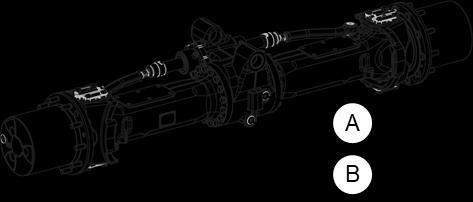
6.5.15. DRAINING SEDIMENT AND WATER FROM FUEL FILTERS
Three kinds of fuel filter are mounted on the machine.
A. Main fuel filter
B. Fuel pre-filter
C. Primary fuel pre-filter
All filters have a water separation feature. Drain contents of filters before level rings reach the lower part of filter elements.
Caution
The water separator contains fuel in addition. When draining the contents of the water separator, wipe up any fuel that splashes on the surrounding area. If not cleaned adequately, it could cause a fire.
WARNING
The water separator contains fuel in addition. When draining the contents of the water separator, wipe up any fuel that splashes on the surrounding area. If not cleaned adequately, it could cause a fire.
DRAINING WATER FROM THE MAIN AND THE PRE-FILTERS
1. Place a tray below pre-filter.
2. Loosen the air bleeder plug and the drain plug.
3. Drain water and sediments until the level ring touches bottom of the case.
4. Tighten the air bleeder plug and the drain plug.
5. In cold weather water may be frozen. Wait until ice melts, then drain the water.
6. Check if there is any leakage and repair it.
Air bleeder plug tightening torque / ISUZU
7.9 to 11.7 Nm (0.8 to 1.2 kgfm)
WARNING
The entry of air into the fuel system will cause engine starting difficult or engine malfunction. After each servicing such as draining fuel tank, fuel filters, changing filter elements, be sure to conduct air bleeding procedure as told in chapter "6.15.7. Bleeding Fuel System".
6.6. EVERY 50 HOURS (WEEKLY SERVICE)
Perform the 10-hours maintenance before starting this maintenance.
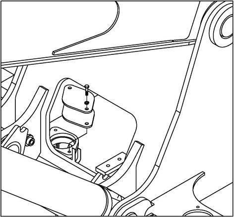
6.6.1. GREASING SWING GEAR BEARING (3 POINT)
1. Lower the work attachments to the ground.
2. Pump new grease 1 or 2 times through the grease nipple using a hand power grease gun.
3. After refilling the grease, wipe off the overflow grease completely.
NOTE
Do not pump to much grease. The dust seals are not capable to hold grease under pressure.
WARNING
Swing only when no one is in the swinging zone.
IMPORTANT
Gearing and bearings of the swing ring must be inspected and re-greased at shorter intervals compared to those specified in the servicing plan under the following conditions :
Excessive temperature
High moisture levels
Exposure to dust and dirt
Marked temperature fluctuations
Continuous swinging
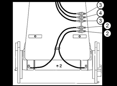
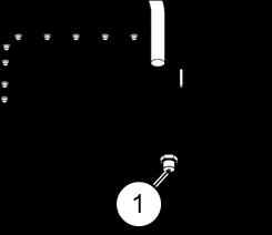
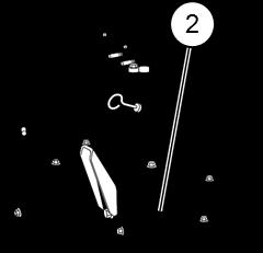
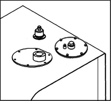
6.6.2. REMOVING SEDIMENT FROM THE FUEL TANK
1) Perform it before starting the machine.
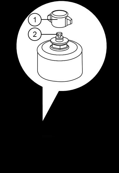
2) Put a container under the drain hose (2).
3) Open drain valve (1) and remove the sediment from the fuel tank. Be careful not to be soaked with the drained fuel.

4) As fuel without water starts to pour out, close drain valve (1) tightly.
IMPORTANT
When cleaning the fuel tank, never use trichloroethylene.
1. Drain valve
2. Drain hose
6.6.3. GREASING DOZER BLADE PINS (12 POINTS)
Check grease filling of dozer blade pins, determined in the following, if necessary renew.
Dozer Cylinder Pins (4 point)
Dozer Upper Connection Pins (4 point)
Dozer Lower Connection Pins (4 point)
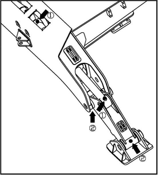
6.6.4. GREASINGOUTRIGGER PINS(8 POINTS)
Check grease filling of outrigger pins, determined in the following, if necessary renew.
Outrigger Cylinder Pins (4 point)
Outrigger Joint Pins (4 point)
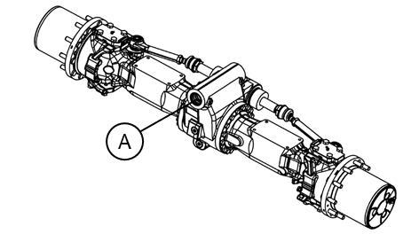
Check grease filling of front axle pin (A), if necessary renew.
6.7. FIRST 250 HOURS
Perform the 10, 50-hours maintenances before starting this maintenance.
6.7.1. REPLACING RETURN FILTER ELEMENT OF HYDRAULIC OIL
WARNING
Before removing cover (3), release the internal pressure of the tank.
1) Release the internal pressure of the tank through air bleeder (1).
2) Loosen the bolts (2) (6 pieces) and remove cover (3). Be careful, since the cover is preloaded by spring (4).
3) Remove O-Ring (5), spring (4) and bypass valve (6), and then pull out element (7).
4) Check and clean the dismantled parts thoroughly. Replace them if they are worn or damaged.
5) Install a new filter element (7).
6) Install bypass valve (6), spring (4) and O-ring (5).
7) When mounting cover (3), fasten the bolts while pressing the cover.
WARNING
If the O-ring (5) is damaged, replace it with a new one.
8) Install the cover.
9) To bleed the air, See Chapter 6.15.8. Bleeding Hydraulic System”. Start the engine and run it at low idle speed for 10 minutes.
10) Stop the engine.
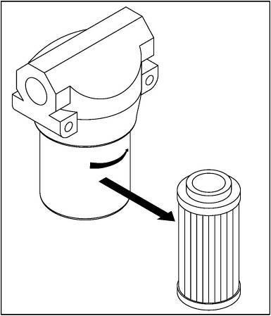
6.7.2. CHANGING PILOT FILTER ELEMENT
Place a container under the filter, remove the filter bowl, and replace the inner element.
6.7.3. GREASING SWING UNIT REDUCTION GEAR
Park the machine on a firm, level ground, lower the front attachment and stop the engine.

Remove the air drain cap (1) and inject proper amount of grease into the grease feed port (2) by using grease gun.
Reassemble the air drain cap (1).
In case of refilling grease without removing the air drain cap, the oil seal may be damaged by internal pressure. It is necessary to refill grease only after removing the air drain cap.
6.7.4. REPLACING SWING UNIT REDUCTION GEAR OIL
WARNING
Immediately after operating the machine, the oil is hot. Allow the oil to cool.
Prepare a container with enough capacity to collect the drained oil.
Dismantle the main control valve cover mounted on the upper frame.
Put the container under the drain plug (3) of swing driving case to collect the drained oil.
Remove the drain plug (3). After draining the oil, install plug.
Withdraw the oil level gauge (1), and refill the oil to the proper level through the oil feed hole (2).
Oil specification Refer to Chapter 6.2. "Oil, Fuel, Coolant And Diesel Exhaust Fluid".
Withdraw the oil level gauge, and wipe it with a clean cloth. Insert the oil level gauge again to check the level.
If oil level is on the 2/3 of the gauge (1), it’s normal. If the oil is below the proper level, refill the oil to the proper level.
If the oil is above the proper level, loosen the drain plug (3), and drain the oil to adjust to the proper level. Then fasten the drain plug (3) and check the oil level again.

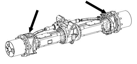
6.7.5. REPLACING FRONT AND REAR AXLE DIFFERENTIAL OIL
Park the machine on a hard and level ground.
Lower the attachment on the ground.
Stop the engine. Remove the starter key.
Clean dust around the plugs.
Place a suitable container under the drain plug.
Remove the oil filling plug (A), then remove the oil drain plug (B).
Completely drain the oil.
Install the drain plug with a new O-ring and tighten it with a torque of 50 Nm
Fill oil to the proper level.
For recommended oil specifications refer to Chapter 6.2. Oil, Fuel, Coolant And Diesel Exhaust Fluid.
Install the filling plug with a new O-ring and tighten it to a torque of 50 Nm.
Check oil level after some minutes and fill up to the specified level, until level remains constant.
A. Oil filling / check plug
B. Drain plug
Figure. Front axle
A. Oil filling / check plug
B. Drain plug

Figure. Rear axle
6.7.6. REPLACING FRONT AND REAR AXLE PLANETARY GEAR OIL
Park the machine on a hard and level ground.
Lower the attachment on the ground.
Stop the engine. Remove the starter key.
Clean dust around the plug (C)
Turn tire, until plug completely comes to the lower position
Open plug and drain the oil completely
Rotate tire 90° and adjust the drain/filling hole horizontally to the ground.
Pour oil into wheel hub until oil overflows from the hole.
For recommended oils refer to Chapter 6.2. Oil, Fuel, Coolant And Diesel Exhaust Fluid.
Install the plug (C) with a new O-ring and tighten it to a torque of 50 Nm.
C. Oil drain/filling plug
Figure. Front axle
C Oil drain/filling plug
Figure. Rear axle

6.7.7. REPLACING TRANSMISSION OIL
The oil change must be carried out as follows:
Park the machine on a hard and level ground.
Lower the attachment on the ground.
Stop the engine. Remove the starter key.
At operating temperature of the transmission and horizontally standing vehicle, open the oil drain plug (F) with O-Ring and drain the used oil.
Clean oil drain plug and sealing surface on the housing and install it again along with new ORing.
Loosen oil filling plug and clean sealing surface on the housing.
Fill in oil. For recommended oils refer to Chapter 6.2. Oil, Fuel, Coolant And Diesel Exhaust Fluid.
Check oil level after about 2 minutes and replenish oil once again if necessary.
Install oil filling plug (E) with new O-Ring and screw it in.
At the initial filling and after repairs has to be considered that some cavities are not yet filled with oil. Due to these cavities, the oil capacity to be filled in at the initial filling is greater than at the later oil changes during the maintenance service, so that the oil level must be checked once again after a driving time of approx. 5 min.
A deviation of ± 3 mm to the oil level plug is permitted.

6.8. EVERY 250 HOURS (MONTHLY SERVICE)

Perform the every 10 hours and every 50 hours maintenances before starting this maintenance.
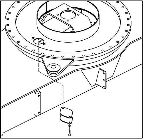
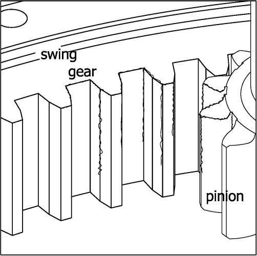
6.8.1. CHECKING SWING RING GEAR GREASE
WARNING
Lower the bucket to the ground to drain the grease at the easiest position, and lock the safety locking system.
1) After starting the engine, swing the upper frame, and lower the attachment to the ground; stop the engine, and lock the safety locking system.
Draining Swing Ring Gear Grease
WARNING
Swing only when no one is in the swinging area.
2) Loosen two bolts and remove the grease filling cover.
3) Check gearing and pinion for damage.
4) Check grease filling:
All tooth faces must be covered with a thin grease film.
If the grease film is not ok add 0.5 kg grease.
If the grease looks contaminated or contains water or mud then drain grease and replace with new grease
1) Put a container under the grease drain port, located below the fill port, loosen two bolts and remove the cover to drain all the grease.
2) Be careful not to be soaked with the drained grease.
3) After the grease is completely drained, install cover.
Prepare a container with enough capacity before draining the grease.
Filling Swing Ring Gear Grease
1) Loosen the two bolts of the grease feed port in front of upper frame, remove the cover, and refill the proper amount of grease.
2) Install the feed port cover.
Important
Gearing and bearings of the swing ring must be inspected and re-greased at shorter intervals than specified in the servicing plan in the event of:
Excessive heat
High moisture levels
Exposure to dust and dirt
Marked temperature fluctuations
Continuous swinging
6.8.2. CHECKING BATTERY ELECTROLYTE LEVEL
Check level before starting the machine.
Warning
Battery gas (hydrogen) is flammable. Do not expose to sources of fire such as open flame, cigarettes, or sparks.
If battery electrolyte is splashed onto clothes or skin immediately flush with clean water. If battery electrolyte is splashed onto eyes, flush with large amounts of clean water and consult a doctor.
Open the cover of the battery box at right side of the machine.
Loosen cap (1). If the level of electrolyte is below the specified level (above 10-12 mm from the plate), refill to the proper level.
Clean the ventilators of battery caps, and tighten it securely.
To prevent the battery from freezing, add distilled water at the beginning of the day’s work and ensure the charging system is fully operational.
6.9. EVERY 250 HOURS HYDRAULIC BREAKER HOURS
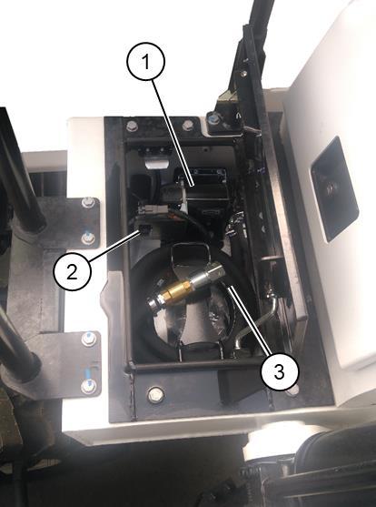
6.9.1. CHANGING HYDRAULIC BREAKER RETURN LINE FILTER
1) Stop the engine.
2) Release the trapped hydraulic pressure from the hydraulic tank breather.
3) Place a container with enough capacity.
4) Remove oil drain plug.
5) Rotate and remove the filter element with span.


6) Before installing the new filter element, replace the old O-rings and gaskets with new ones.
7) Install the new element.
6.10. EVERY 500 HOURS (3 - MONTH SERVICE)
Perform the 10, 50 and 250 hour maintenance before starting this maintenance.
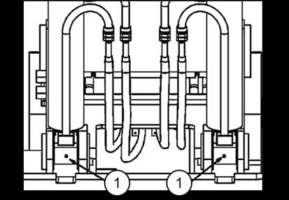
6.10.1. CHANGING FUEL FILTER ELEMENTS
WARNING
Keep away from open flames. After replacing the filter element, wipe up any spilled fuel. Also, make sure there is no fuel leakage from the filter. Leaking fuel will cause fire. To avoid damaging the element, be careful not to over tighten the element assembly.
Caution
The fuel filter element may be clogged faster depending on the amount of dust particles in the fuel. Therefore, the element may need to be changed much earlier than 500 hours. If the low engine output or engine stall failure is encountered, changing fuel filter element may solve the problem.
Caution
Figure shows the valve positions for engine operation. When any fuel filter replacement is to be done, pay attention to valve positions explained in the procedure below.

While replacing the fuel filters, fuel line cleaning system protects the fuel line system from contamination. During the fuel filter replacement, follow the steps given below:
1. Park the machine in a suitable place complying with the safety rules.
2. Turn starter key to the “OFF” position.
3. Close Valve 1 (coming from the fuel tank). And Valve 2 (feeding the engine)
4. Place a suitable container under the filters and under the main filter drain hose in order to avoid spillage.
5. Replace the fuel filter elements with the new ones.
6. Open Valve 1 (coming from the fuel tank).
7. Open the Air Bleeding Plug on the main fuel filter.
Turn the key starter switch to the "ON" position. Fuel transfer pump starts operating. Meanwhile, turn the handle of the hand pump to unlock it and manipulate the hand pump to speed up bleeding the air out. Continue the process until bubble free fuel comes out from the drain hose. Turn the key starter switch to the "OFF" position and tighten the Air Bleeding Plug. Take the handle of the hand pump back to its original place and fix it.
Note
If bleeding process does not complete in 5 minutes, do not keep the starter key at “ON” position. Otherwise the pump can be damaged. Take the starter key to “OFF” position.
8. Open valve 3 (flowing towards to the fuel tank), turn the key starter switch to the "ON" position and re-operate the fuel transfer pump. Let the fuel transfer pump run for 30 seconds, so contaminants can be filtered. After 30 seconds is over, turn the key starter switch to the "OFF" position.
9. Then open Valve 2 (feeding the engine) and close Valve 3 (flowing towards the fuel tank).
10. Finally, be sure that the positions of the valves are as given below

Valve 1 (coming from the fuel tank): OPEN Valve 2 (feeding the engine): OPEN Valve 3 (flowing towards the fuel tank): CLOSED
11. Start the engine, and check If there is any fuel leakage.
1. Air bleeding plug
2. Filter body
3. Filter element
4. Float
5. O-ring
6. Element case
7. O-ring
8. Drain plug
6.10.2. REPLACING ENGINE OIL AND OIL FILTER
The engine oil provides engine cooling and flushes out the filth inside the engine. The engine oil has a significant impact on the performance and service life of the engine and fuel economy, so only use recommended oil in your engine.
Check if there is any oil leakage around the oil filter or the drain plug.
1. One-touch type drain plug (Isuzu 4HK1)
CAUTION
Do not perform abrupt engine idling, which may cause an engine failure.
8. Stop the engine. Wait for 20 to 30 minutes and then re-check the engine oil level using the oil level gauge.
Isuzu
1. Clean around the oil filling cap so that foreign matter does not enter into the engine. Remove the oil filling cap.
2. Place a container under the drain plug and the oil filter.
3. Loosen the cap of the oil drain plug to remove it. Tightly attach the oil drain hose to the oil drain plug all the way to the end to drain the oil.
4. When the oil is completely drained out, disconnect the oil drain hose, and wipe off the oil attached to the drain plug.
5. Securely tighten the cap of the oil drain plug. (Tighten the cap lightlyuntil it is seated, and then tighten it further for approx. 60° - 90°)
CAUTION
Make sure to wipe off any dirt on the drain plug before installing it.
WARNING
During inspection and service, injuries may occur due to hot engine body, coolant or engine oil. For safety, conduct service work after the engine is stopped and cools down sufficiently.
It is very dangerous to inspect and service the rotating parts. For safety, conduct service work after the engine is stopped. Also, make sure that it does not start during work.
Periodically replacing engine oil and engine oil filter will affect the performance and the service life of the engine.
For oil specifications refer to "Chapter 6.2. Oil, Fuel, Coolant and Diesel Exhaust Fluid Chapter".
When the oil filter is clogged, “FILTER CLOGGED
1” warning is indicated on the instrument panel. In such a case, replace the filter regardless of the specified replacement schedule.
WARNING
While adding oil, be careful not to spill any oil. Clean up spilled oil with a workshop rag, Otherwise it could catch fire.
Do not leave flammable items such as clothes and work gloves in the engine compartment. Such items could catch fire. Also, do not leave any of the tools.
Right after operating the machine the engine oil temperature is high. Before replacing the engine oil wait for the oil to cool down and be careful not to get burned.
Isuzu
6. Remove the oil level gauge and carefully fill engine oil through the oil filler.
7. Install the oil level gauge and the filler cap. After refueling wait for 5 minutes before starting the engine. Start the engine and run it at idle speed.

Caution
When replacing the engine oil, also replace the engine oil filter.
Do not perform abrupt engine idling, which may cause an engine failure.
Check the engine oil level using the oil level gauge. Do not fill oil above the "FULL" mark on the oil level gauge, because adding too much oil may cause an engine malfunction. Do not let the oil level falls below the "ADD" mark on the oil level gauge, because the engine may be damaged if the oil level falls.
Disposal and treatment of the drained oil must be conducted in accordance with the specified procedure.
6.10.3. REPLACING THE OIL FILTER
The engine oil filter has the function of removing the dirt, dust and other impurities mixed into the engine oil. The engine filter has a significant impact on the performance and service life of the engine, so use of the "Hidromek genuine parts" is recommended.
Caution
When installing the oil filter, make sure that the gasket does not get caught at the rim. This could cause oil leakage.
Any dirt on the drain plug should be wiped off before installing it. Do not perform abrupt engine idling, which may cause an engine failure. After replacement of the filter, perform a test for the engine and confirm that there is no oil leakage around.
Caution
When replacing the engine oil filter, it is recommended to use a Hidromek genuine oil filter. An unapproved oil filter may cause an engine damage. Replace the engine oil and the oil filter at the same time. Disposal and treatment of the waste oil and the oil filter must be conducted in accordance with the specified procedure.
1. Clean around the oil filling cap so that foreign matter does not enter into the engine. Remove the oil filling cap.
2. Place a container under the oil pan and the oil filter.
3. Remove the oil pan drain plug and drain the oil.
4. Use the special oil filter wrench to remove the filter.
5. Apply a thin layer of clean engine oil to the gasket before installing the filter.
6. Install the new filter. Screw the filter until the gasket comes in contact with the seal surface, and then tighten it by one full turn using the special oil filter wrench.
7. Confirm that the engine oil drain plug is securely tightened.
8. Install the oil level gauge and the filler cap. After refueling wait for 5 minutes before starting the engine. Start the engine and run it at idle speed. Check if there is any oil leakage around the oil filter or the drain plug.
9. Stop the engine. Wait for 20 to 30 minutes and then re-check the engine oil level using the oil level gauge.
Caution
Prevent dust particles from entering through filler port during replacement. Entry of dust particles may cause engine damage or accident.
Filling the engine oil above the “Max” marking or below the “Min” marking on the oil level gauge may cause engine damage or accident.

Drain the engine oil to the “Max” marking if the oil level is above “Max” marking. Also, add engine oil to the “Max” marking if the oil level is below the “Min” marking.
The strainer is incorporated in the supply pump inlet side joint bolt. Clean the strainer with compressed air and rinse it in a container filled with fuel.
CAUTION
When the filter is removed, make sure to replace the gasket and clean the magnet portion inside the cover.
1. Remove the wirings attached on the pump cover. Rotate the cover with a wrench and remove it.
CAUTION
When removing since the fuel present inside the pump, use a container or something to receive the fuel does not splash on the engine. Also, be cautious of fire.
2. Remove the filter and the gasket, and replace or clean them.
CAUTION
Do not disassemble the piston and its parts locating at the inside center of the electromagnetic pump. When removing the gasket, hold the outer part of the gasket with your fingers and pull it out.
Clean the filter with clean diesel fuel, and blow off the dirt and other impurities using high-pressured air. Then, install the filter and install a new gasket.
3. Install the cover. When installing, use a wrench and fully tighten it until the filter is properly seated.
CAUTION
After the cover has been installed, make sure to check the airtightness. The interval of replacement or cleaning should be shortened depending on the status of fuel management and refuel.
6.10.6. CHECKING ANTIFREEZE DENSITY
Check the density of anti-freeze. Use ethylene glycol antifreeze mixed with quality water at a ratio of 50:50 to provide protection against freezing at temperatures down to -37°C. Use a high quality tester and follow the manufacturer’s instructions to obtain an accurate reading.
Coolant specification Refer to Chapter 6.2. "Oil, Fuel, Coolant And Diesel Exhaust Fluid".
6.10.7. CHECKING AND CLEANING RADIATOR, OIL COOLER AND CONDENSER FIN
Warning
Compressed air, steam or water can cause personnel injury. Wear safety goggles or a facemask.
Do not use steam to clean the air condenser.
After opening the engine hood and the left side door of the machine, loosen the wing bolt and remove the mesh in front of oil and water coolers. Blow away any mud, dust and leaves stucked on the radiator fin and oil cooler fin with compressed air. Also clean the mesh. Clean the condenser fin of the air conditioner; water may be used instead of the compressed air.
Check the rubber hose for signs of wear or crack. If damaged, replace it. Check the hose clamp for looseness.
Important
When using the compressed air, keep the nozzle at some distance from the fins to prevent any damage. If the fin is damaged, this may cause leakage or overheating. Under dusty environment conditions, check it every day regardless of its maintenance interval.
6.10.8. CHECKING FRONT/REAR AXLE DIFFERENTIAL OIL LEVEL
Clean dust around the oil check plug (A).
Remove the oil check plug (A).
Check the oil level in the axle. Oil level should be at the lower point of the hole.

If the level is low, add oil and top up the level until oil overflows.
Install the plug and tighten it to 50 Nm.
Wait for 5 minutes and check the level again.
6.10.9. CHECKING FRONT/REAR AXLE PLANETARY GEAR OIL LEVEL
Clean dust around the bolt.
Turn tire and bring the oil filling plug (B) to a horizontal position with the ground.

Remove the oil filling plug (B)
Check the oil level in the planetarygear. Oil level should be at the lower point of the hole.
If the level is low, add oil and top up the level until oil overflows.
Install the plug and tighten it to 50 Nm.
Wait for 5 minutes and check the level again.
Grease from grease nipples shown in figure
For recommended grease refer to Chapter 6.2. Oil, Fuel, Coolant And Diesel Exhaust Fluid.
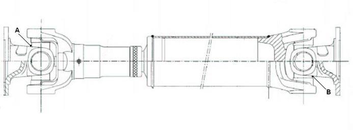
6.10.11. GREASING FRONT / REAR SHAFT
Check grease filling on nipple A and B, if necessary renew.
Greasing Refer to Chapter 6.7.3. Greasing Swing Unit Reduction Gear.
6.11. EVERY 1000 HOURS (6 MONTHS SERVICE)
Perform the 10, 50 250 and 500 hours maintenances before starting this maintenance.
6.11.1. REPLACING SWING UNIT REDUCTION GEAR OIL
Replacing oil Refer to Chapter 6.7.4. Replacing Swing Unit Reduction Gear Oil.
6.11.2. CHANGING PILOT FILTER ELEMENT
For changing pilot filter element, see Chapter 6.7.2. Changing Pilot Filter Element.
6.11.3. CHANGING RETURN FILTER ELEMENT OF HYDRAULIC OIL
For replacing return filter element of hydraulic oil, see Chapter 6.7.1. Replacing Return Filter Element Of Hydraulic Oil.
6.11.4. ENGINE VALVE CLEARANCE CHECK
This check must be performed by a HİDROMEK Authorized Service
6.11.5. STARTER AND ALTERNATOR CHECK AND CLEANING
This check must be performed by a HİDROMEK Authorized Service.
6.11.6. CYLINDER COMPRESSION CHECK
This check must be performed by a HİDROMEK Authorized Service.
6.11.7. ADJUSTMENT OF TENSION OF THE AIR CONDITIONER BELT
IMPORTANT
If the tension of the belt is not correct: The performance of compressor is reduced and the belt and compressor may be damaged. Frictional sound (halt) is generated. Adjust the Vbelt tension. If torn away, replace it. Therefore, check the tension of the air condition belt should any of these abnormalities are found.
Press the center of belt between pulleys with force of 10 kg. If it can be depressed about 7-10 mm, belt tension is normal.
Id tension is to be adjusted, loosen the nut of the idler pulley, and adjust the belt tension with adjusting bolt.
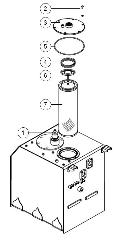
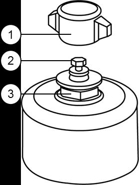
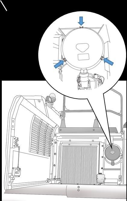
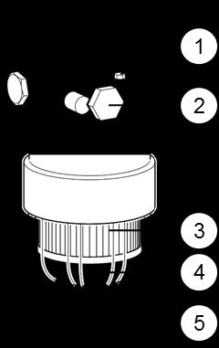
6.11.8. REPLACINGTHE FILTER OFHYDRAULIC TANK BREATHER
In dusty working environments, the hydraulic tank breather will become blocked after a short period of time.
Follow the steps below to replace the filter element of hydraulic tank breather:
1. Remove air breather plastic cap (1) on the air relief valve of the breather.
2. Press the relief valve (2) to release the pressure in hydraulic tank.
3. Remove nut (3), washer (4) and disassemble breather cover (5).
4. Now, remove breather filter element (6).
5. Clean the cover and surrounding and do not let any dirt enter into the hydraulic system.
6. Install new filter (6).
7. Re-mount breather cover and tighten nut to fix it.
8. Install washer and air breather plastic cap to secure the pressure relief valve.

6.12. EVERY 2000 HOURS (ANNUALLY) SERVICE
Perform the 10, 50, 250, 500 and 1000 hours maintenances before starting this maintenance.
6.12.1. REPLACING OIL AND CLEANING OR REPLACING SUCTION FILTER ELEMENT OF HYDRAULIC TANK
Warning
Stop the engine before performing any maintenance and service on the machine. Immediately after stopping the machine, the oil is hot. Allow the oil to cool down. Before removing the drain plug and the suction filter element cover, release the internal pressure of the tank.
Prepare a container with proper capacity to collect the drained oil.
1. Swing the upper frame so that the drain plug at the bottom of the hydraulic tank is located between the left and right tracks.

2. Retract the arm and bucket cylinder to its full stroke, and lower the bucket to the ground.
3. Lock the safety locking system and stop the engine.
12. Fill the hydraulic tank to the proper level through oil filling port (12).
Check the hydraulic oil level through the gauge on side of hydraulic tank. The centerline on the oil level gauge is the correct level.
Follow the procedure in “Chapter 6.5.10. Hydraulic Oil Level Check” to check oil level in tank.
For oil specifications refer to "Chapter 6.2. Oil, Fuel, Coolant and Diesel Exhaust Fluid".
When the machine is delivered from the factory, the hydraulic system is filled with “ISO VG46” grade oil.
4. Release the internal pressure of the tank through the air breather (1).

5. Remove the bolt (2) and washer (3).
6. Remove the bolt (5), then remove the filter element cover (6), the O-Ring (7) and the filter element (8).
If the suction filter element (8) is damaged, replace it with a new one.
7. Put a container under the drain plug (9) to collect the drained oil. Remove the drain plug (9) and drain the oil.
8. Replace the O-Ring (10) on the drain plug (9). After draining the oil, tighten the drain plug (9). Tightening torque of the drain plug is 18 kgf.m.
Caution
When removing drain plug (9), be careful not to be soaked with the drained oil.
9. Remove the suction flange (15) and replace the O-ring (14).
10. Clean the removed parts and assemble the parts in reverse order.
11. Remove the plug (11) and filling plug (12) on the return filter cover (13).
13. Bleed the hydraulic system.
Hydraulic system needs to be bled after below situations:
After replacing the hydraulic oil
After replacing the return filter element
After cleaning/replacing the suction filter element (8).
For more information refer to “Chapter 6.15.8. Bleeding Hydraulic System”.
14. Check the hydraulic oil level through the gauge on side of hydraulic tank.
6.12.2. REPLACING FRONT AND REAR AXLE DIFFERENTIAL OIL
For replacing front and rear axle differential oil, see Chapter 6.7.5. Replacing Front and Rear Axle Differential Oil
6.12.3. REPLACING FRONT AND REAR AXLE PLANETARY GEAR OIL
For replacing front and rear axle planetary gear oil, see 6.7.6. Replacing Front and Rear Axle Planetary Gear Oil
6.12.4. REPLACING TRANSMISSION OIL
For replacing transmission oil, see Chapter 6.7.7. Replacing Transmission Oil.
6.13. EVERY TWO YEARS OF SERVICE
6.13.1. CLEANING COOLING SYSTEM AND REPLACING COOLANT
WARNING
Inspection, filling or replacement of the coolant should be performed after the engine is sufficiently cooled down. Allow the engine to cool down.
Do not loosen or remove the radiator cap or the reservoir cap while the coolant temperature is still high. Hot vapor or boiling water mayburst out and cause a burn.
When the engine has cooled down sufficiently and the coolant temperature has dropped down, cover the cap with a cloth, etc. and loosen it slowly to release the internal pressure, then remove it.
WARNING
Tie up long hair and do not wear loose clothing or dangling jewelry. Do not place your hands or tools near any rotating parts. You may get caught by the rotating parts and serious injury or death could result.

Caution
The water which is mixed with the long-life coolant (LLC) has to be tap water (soft water), not well water or river water.
Use distilled water in the radiator. Do not use water from a well, river, sea and waste water since the cooling system can be damaged. If you add coolant to the system, use coolant in the same concentration with the coolant in the system.
When refilling coolant, flush out the system with distilled water.
Never mix different brands and different classes of antifreeze. For example, never mix standard life ethylene glycol antifreeze with extended life ethylene glycol antifreeze. If they are mixed, the protection level will be reduced.
See "Chapter 6.2. Oil, Fuel, Coolant and Diesel Exhaust Fluid" for more information about Coolant and Water Specifications and their mixing ratios.
WARNING
The antifreeze is flammable, keep away from flames.
WARNING
When removing the drain plug, be careful not to be soaked with the coolant.
WARNING
The coolant is toxic and must not be ingested. If the coolant is mistakenly ingested, immediately vomit it and seek prompt medical attention. When the coolant gets in your eyes, rinse it off immediately with a large amount of water for 15 minutes or longer. Also, if still an abnormality such as irritation is felt, seek medical attention. When the coolant gets on your skin, rinse it off using a soap with a large amount of water. Also, if an abnormality is observed, seek medical attention.
The coolant is flammable. Keep flames away from it. Also, the coolant could catch fire if it comes in contact with a hot surface, such as the exhaust manifold. Pay attention to prevent this from happening.
CAUTION
Replace the coolant periodically. Failure to periodically replace the engine coolant may cause rust due to engine coolant deterioration, possibly resulting in water leakage, clogging of the radiator or heater core, or failure of the urea SCR system.
CAUTION
Do not use the long-life coolant at any concentration other than the one specified. When the long-life coolant concentration is 60% or higher, overheating is likely to occur, while when it is 30% or lower, the anti-corrosion function is not provided sufficiently. Using the long-life coolant at any concentration other than the one specified may reduce the antifreezing performance, and the coolant may freeze. Adjust the concentration of the coolant depending on the situation. If the coolant level decreases rapidly, consult Hidromek Authorized Service for an inspection or repair.
While changing coolant, flush the cooling system with clean water and drain all of the water after flushing. Also, clean the radiator, radiator cap, and intercooler.
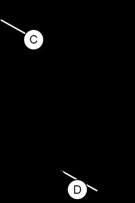
Draining the Cooling System
1. Remove the radiator cap (C).
2. Remove the coolant drain plug (D) of radiator and drain the coolant.
3. Loosen and remove the air bleeding plug (E) on the EGR cooler.
Caution
After the coolant is drained, do not start the engine. If there is no water in the radiator, it could cause engine seizure. Hand tighten the drain plug of the radiator. Tightening with pliers or some other tool could damage it.
Disposal and treatment of the drained coolant must be conducted in accordance with the specified procedure.


Follow the procedure below to change the coolant:
1. Park the machine on a hard and flat ground.
2. Lower the bucket to the ground. Stop the engine and remove the starter key. Disconnect the battery. Allow engine coolant to cool down to avoid burning.
3. Open the engine hood.
4. Place an appropriate container under the radiator and engine to collect the coolant that will be drained.
4. Remove the filling cap of the coolant reservoir.
5. Remove the coolant drain plug of engine located on the right side of the cylinder block, and drain the coolant inside the engine block.
6. Install the coolant drain plug of the radiator and the coolant drain plug of the engine.
7. Install the air bleeding plug on the EGR cooler.
Cleaning the Coolant System
If the cooling system circuit is contaminated due to sludge particles or scaling, cooling efficiency will be lowered. Periodically clean the cooling circuit.
Preferably, add hot water into the radiator which has suitable properties as recommended in Chapter 6.2.
1. Fill the radiator with tap water up to the top of the opening.
2. Check and clean the radiator cap. Replace the cap if it is damaged.
3. Firmly close the radiator cap.
4. Fill the reservoir tank with tap water up to the "MAX" line.
5. Close the cap of the reservoir tank.
6. Start the engine and run at idle speed for 20 minutes, and then stop the engine, wait until it cools down sufficiently, and drain the water. If the water is dirty, repeat this flushing procedure until the coolant appears totally clean.
Filling the Cooling System
Warning
Pay attention to prevent overflowed coolant not to splash onto the exhaust system components. The coolant may catch fire, so make sure to wipe it off completely.
E. Air bleeding plug (4HK1)
1. Mix antifreeze and water in a container. For more information about Long Life Coolant specifications refer to "Chapter 6.2. Oil, Fuel, Coolant and Diesel Exhaust Fluid”.
2. Loosen air bleeding plugs on the water pipe and on the EGR cooler. Then fill Long Life Coolant slowly from the radiator inlet. To avoid air intrusion to the cooling system, the Long Life Coolant should be filled slowly.
Caution
When the air bleeding plug of the water pipe and EGR cooler has been loosened, make sure to replace the packing with a new one.
NOTE
It is not necessary to bleed air from the EGR cooler if the vehicle is equipped with a pressurized reserve tank.
3. Once Long Life Coolant starts to overflow from the air bleeding plugs on the water pipe and EGR cooler, wait until no more air is coming out and then tighten the bleeding plugs.
4HK1
Tightening Torque
4. Fill the radiator with Long Life Coolant to the top of the filler opening.
5. While manually pressing the radiator upper hose several times to bleed any air from within the hose, add an amount of Long Life Coolant equivalent to the amount in which the coolant level has dropped so that the coolant level is up to the brim of the radiator filler neck.
6. Repeat Step 5 until the coolant level no longer decreases.
7. Firmly close the radiator cap.
8. Fill the reservoir tank with the Long Life Coolant up to the "MAX" line and close the cap of the reservoir tank.
9. Bleed the air from the coolant piping of the urea SCR dosing module. Remove the coolant piping connected to one side of the dosing module and check if any coolant is overflowing before reconnecting.
10. Completely wipe up any coolant that has overflowed.
11. Idle the engine for 5 minutes and then stop the engine.
12. After making sure that the coolant has cooled down, remove the radiator cap, and if the coolant level has lowered, add the coolant up to the radiator filler opening. If the coolant level is abnormally low, check for coolant leaks.
13. Firmly close the radiator cap.
14. Start and warm up the engine. Bleed any air from inside the heater circuit. Set the temperature and blower speed to their maximum. Also, warm the engine by accelerating the engine speed to around 1,500rpm or more until the engine coolant temperature gauge stabilizes.
15. Touch the upper hose with the engine running and check whether it has become warm. If it has not become warm, return to Step 14.
16. Idle the engine for 5 minutes and then stop the engine.
Note
When the engine has cooled down, the inside of the radiator will be at a negative pressure and coolant will automatically be supplied to the radiator side from the reserve tank.
17. Remove the radiator cap after confirming that the engine coolant has cooled down and add coolant up to the radiator filler neck if the coolant level has decreased. If it has decreased significantly, inspect for engine coolant leakage. When leakage is found, contact Hidromek Authorized Service.
18. Firmly close the radiator cap.
19. Fill the reservoir tank with Long Life Coolant up to the "MAX" line, and close the cap of the reservoir tank.
Caution
If the coolant in the reservoir tank has decreased the next morning, add engine coolant up to the "MAX" line.
Cleaning the Radiator Exterior
When radiator fins are clogged with filth such as dirt and dry grass, it may interrupt the air flow and cause overheat of the engine cooling system.
Periodically check if the radiator is clogged and when it is clogged clean the radiator fin with steam or pressured water.
If the front of the radiator is clogged with mud or dirt, wash it and ensure that air can flow through the radiator core without obstruction.
Caution
Take care to prevent the spilled coolant from getting into the exhaust system and its components. If you spill coolant, wipe it properly, or this could lead to a fire.
Checking Coolant Level
To release the air in the coolant system, operate the engine about 10~15 minutes at a low idle speed and wait for the coolant temperature reach to proper degree (90~95°C).
Turn on the heater during this warm up.
Stop the engine and wait the engine to cool down until 40 °C.
Check the coolant level in the coolant reservoir after the engine is cooled down. Fill the coolant reservoir to the maximum level.
6.14. EVERY 4500 HOURS
6.14.1. INSPECTING AND CLEANING THE INJECTOR
This maintenance should be performed by Hidromek Authorized Service.
6.14.2. INSPECTING AND CLEANING THE EGR VALVE
This maintenance should be performed by Hidromek Authorized Service.
6.14.3. INSPECTING AND CLEANING THE EGR COOLER
This maintenance should be performed by Hidromek Authorized Service.
6.14.4. INSPECTING THE TURBOCHARGER (IF NECESSARY CLEAN THE BLOWER)
This maintenance should be performed by Hidromek Authorized Service.
6.14.5. INSPECTING THE UREA SCR SYSTEM
This maintenance should be performed by Hidromek Authorized Service.
A. Coolant level gauge
B. Coolant reservoir filling cap
6.15. WHEN REQUIRED
6.15.1. FILLING FUEL (FUEL TRANSFER PUMP)
Important
Stop the engine when refueling. Do not run fuel transfer pump dry for more than 30 seconds, since excessive wear and damage may occur.
Be careful not to block the pump exit by closing the valve or with a folded hose. Check the pump strainer frequently. Do not run the pump with a clogged strainer to prevent cavitation. Dirt will cause overheating and damage the pump. Keep pump away from water and rain. Maximum operation time is 25 minutes, do not exceed. Usage of pump over recommended operation time will cause heating and pump damage.
The pump is used to transfer fuel to the fuel tank.
A cap and a strainer are installed at the end of the suction line hose to prevent any foreign materials to enter the pump and the fuel tank.
To transfer fuel into the fuel tank:
Turn the cap at the end of the hose to counter clockwise to open the holes on the cap.
Dip the suction hose into the fuel source tank to transfer fuel into the fuel tank.
Open the valve.
Turn pump switch to “ON” position.
Note
Pump refueling capacity is 35 l/min. Be careful not to overfill the fuel tank.
When fuel level in the tank becomes full, the red pin floats up.
Turn switch to “OFF” position when refueling is completed.


Take suction hose out from the fuel source tank and run pump for 2 or 3 seconds to drain remaining fuel from suction hose.
Close the valve.
To prevent any foreign materials from entering the hose, turn the cap to clockwise direction and tighten. This will close the fuel holes on the cap. Keep the strainer and the hose clean.
6.15.2. REPLACING AIR CONDITIONER FILTERS
Air conditioner filters are used to prevent foreign materials and smell from coming inside the vehicle and provides a pleasant atmosphere.
If not replaced for a long period, the filters will be blocked by foreign materials and the air flow will extremely decrease. The blower motor may make noise, and bad odor come in through the discharge ports. Check for existence of any of these signs and if necessary clean or replace the filters.
Filters should be frequently checked and replaced depending on the area, device and work site environment where air pollution is serious and dust or smoke is largely generated due to bad road condition.
The air conditioner unit has two types of filters.
External filter: It filters dirt and dust particles outside. If it is clogged, clean it by using pressurized air (below 2 kgf/cm2, 28 psi). If not well cleaned or damaged, use a new filter.
Internal filter: It filters dust particles in the air which is circulated inside the operator’s cab. Check if it is clogged, clean it using pressurized air (below 2 kgf/cm2, 28 psi) or water. If it is still dirty, or damaged then replace it with the new one.
Do not change the orientation of the filters!

IMPORTANT
When water is used to clean a mesh filter, ensure that it is completely dry before installing.
WARNING
All service and inspection of air conditioning system should be performed while the starter switch is in OFF position.
If using compressed air to clean the element, make sure you wear safety glasses.
6.15.3. REPLACING OR IF NECESSARY CLEANING AIR FILTER OUTER ELEMENT
Caution
Never clean or replace the air cleaner while the engine is running. When cleaning the element with compressed air, wear goggles. Never start the engine without air cleaner or with a damaged air cleaner. Shorten the inspection/cleaning and replacement intervals if the engine is used particularly in a dusty environment. Do not clean and reuse the inner element.
6.15.3.1. CHECKING AIR FILTER
Warning
Do not remove the inner element except for replacement. Clean the element with compressed air. Make sure the air pressure does not exceed 150 kPa (1.5 bar).
Never attempt to clean the element by knocking it against another object or by striking it. If the element blackened by oily soot, replace it with a new one irrespective of the specified replacement interval.
Make sure the elements are fitted in securely. If they are not fitted securely, dust or other foreign materials may be sucked into the engine and prevent a normal operation.
When the signal on the instrument panel comes on, it means the air filter is clogged. Replace the outer element. HIDROMEK does not recommend cleaning the outer element, but if it is necessary to clean it consider the following information.
1. Cover
2. Protection cap
3. O-ring
4. Cover
5. Marking
6. Vacuum valve

7. Outer element (main element)

8. Inner element (safety element)
9. Body
6.15.3.2. CLEANING OUTER ELEMENT
Remove the element.
Check the level of contamination in the element, and then clean the element.
Clean the dust bowl.
Blow clean compressed air form inside of the element 150 kPa (1.5 bar) towards the pleats. Do not blow air closer than 25 mm.
When all parts are cleaned, assemble them in the reverse order of the disassembly procedure.
Hold a light source inside the element and inspect the filter media.
Replace the element if the filter paper has small holes, badly abraded areas, or any other damage or if the seal is damaged.
6.15.3.3. REPLACING AIR FILTER INNER ELEMENT
Caution
Shorten the inspection/cleaning and replacement intervals if the engine is used particularly in a dusty environment. Do not clean and reuse the inner element. Replace the outer and inner elements at the same time.
6.15.4. BLEEDING FUEL SYSTEM
If the engine has stalled due to running out of fuel or the fuel filter has been replaced or draining water from the fuel filters then air gets in the fuel system. If air enters into the fuel system, it may cause engine starting difficulty or engine malfunction. Therefore, air in the fuel system needs to be bled before starting the engine.
WARNING
There is a risk of fire. Do not smoke or use a lighter or other open flame and stop the engine before bleeding the fuel system.
Caution
If fuel spills on the exhaust pipe, wipe it up completely. Spilled fuel may start fire due to heat generated by the engine. When bleeding the fuel system, be careful not to get hurt by the parts in the work area that have sharp edges.
INFORMATION
During air bleeding operation, fuel will come out the bleeding plug. To prevent fuel from spilling over the surrounding parts, install a hose in the air bleeding plug to collect spillage in a container. Use a transparent hose so air bubbles inside the fuel could be seen through the hose.
Before Starting the Engine
1. Install a hose to the air bleeding plug (1) on the fuel filter. Fit a tray below the fuel main filter.
2. Turn the starter switch to "ON" position to activate the electromagnetic pump.
3. Loosen the bleeding plug adequately and operate the hand pump (2) until the fuel comes out.
4. Tighten the bleeding plug, and operate the hand pump until the fuel filter is filled with fuel (10 times or more).
5. After waiting for approximately a minute, loosen the plug and bleed out the air in the fuel filter. (This work must be repeated a minimum of three times until no more air comes out from the plug).
6. Tighten the plug firmly and wipe the fuel in the surrounding area.
7. Operate the hand pump (10 to 15 times) till it is filled with fuel and then send fuel to the engine.
Warning
Check the filter case for fuel leakage. Spilled fuel can cause fire.
Start the engine and check the fuel system for leakage. Pay attention to safety as leakage causes fire.
After Starting the Engine
8. Start the engine, but do not raise the engine speed on machine side.
9. If the engine does not start at this time, repeat the procedure from Step 4.
10. After starting, maintain the idle speed for 5 seconds.
11. Slowly increase the engine speed and keep this for three minutes.
12. Operate the engine speed to maximum on the machine side. (Repeat this operation several times)
13. Return to idling speed.
If the air bleeding work is insufficient then it could lead to faults in the engine. Therefore, the procedures after starting the engine should always be implemented.
6.15.5. BLEEDING HYDRAULIC SYSTEM
Hydraulic system should be bled after replacement of hydraulic cylinders or any other part of the hydraulic circuit or changing hydraulic oil.
Set a low engine speed and follow the procedure below:
1. Operate each cylinder 100 mm forward and backward. Repeat this 4 or 5 times.
2. Operate each cylinder at full stroke. Repeat it 34 times.
6.15.6. CHECKING AIR CONDITIONER REFRIGERANT AMOUNT
If the cooling or heating effect of the air conditioner is poor, there may be lack of refrigerant (gas). Contact Hidromek dealer for inspection and repair.
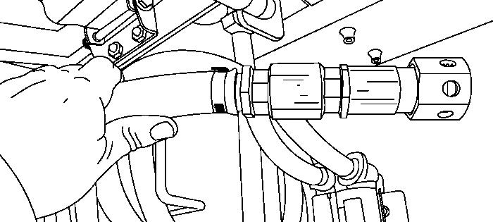
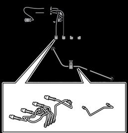
6.15.7. REPLACEMENT OF THE FUEL PIPING
When the fuel injection pipes (high-pressure piping) are removed, do not reuse them again. Because they have metal to metal contact sealing.
If they are reused, the seal surface may be shifted which will cause fuel leakage. Also due to very high pressure in the fuel piping, fuel jet could cause damage or death.
7. SPECIFICATIONS
7.1. TECHNICAL SPECIFICATIONS OF HMK 210 W-4

TECHNICAL SPECIFICATIONS OF HMK 210 W-4
TECHNICAL SPECIFICATIONS OF HMK 210 W-4
ENGINE
Manufacturer ISUZU
Model AR-4HK1X
Emission class 97/68 EC, TIER-4 (StageIV)
Type 4 cylinder, vertical inline, water cooled, direct injection, overhead camshaft, with turbocharger
Gross Power (SAE J1995)
128.4 kW @ 2000 rpm
172.2 HP @ 2000 rpm
Net Power (SAE J1349) 120.7 kW @ 2000 rpm
161.8 HP @ 2000 rpm
Maximum torque 670 Nm, 1600 rpm
Number of cylinder 4
Bore x Stroke Ø115 mm x 125 mm
Total displacement 5193 cc
TECHNICAL SPECIFICATIONS OF HMK 210 W-4
TECHNICAL SPECIFICATIONS OF HMK 210 W-4
OPERATOR'S CAB
Length
1854 mm
Height 1681 mm
Width 1000 mm
ROPS: ISO 12117-2:2008
Safety
Heating and ventilation
Front
Window
FOPS : Level I / ISO 10262
High capacity automatic air conditioner is standard equipment. Fan speed, air temperature and vents can be selected on manual control. Heating system is created to distribute air in the best way.
Fully-open, laminated safety glass
Side Left Sliding open, tempered safety glass Right Fixed, tempered safety glass
Rear Fixed, tempered safety glass
Function
Seat
Adjust
Air suspended weight adjustment, lateral suspension, reclining, seat and seat base fore-aft adjustment, seat pan depth and angle adjustment, 4 position seat height adjustment, headrest height and angle adjustment
Reclining Rear: 70
Horizontal (Seat) 80 mm
Horizontal (Seat Base) 50 mm
Suspension stroke 50 mm
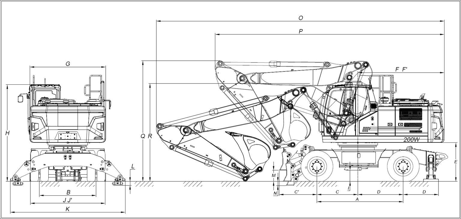
TECHNICAL SPECIFICATIONS OF HMK 210 W-4
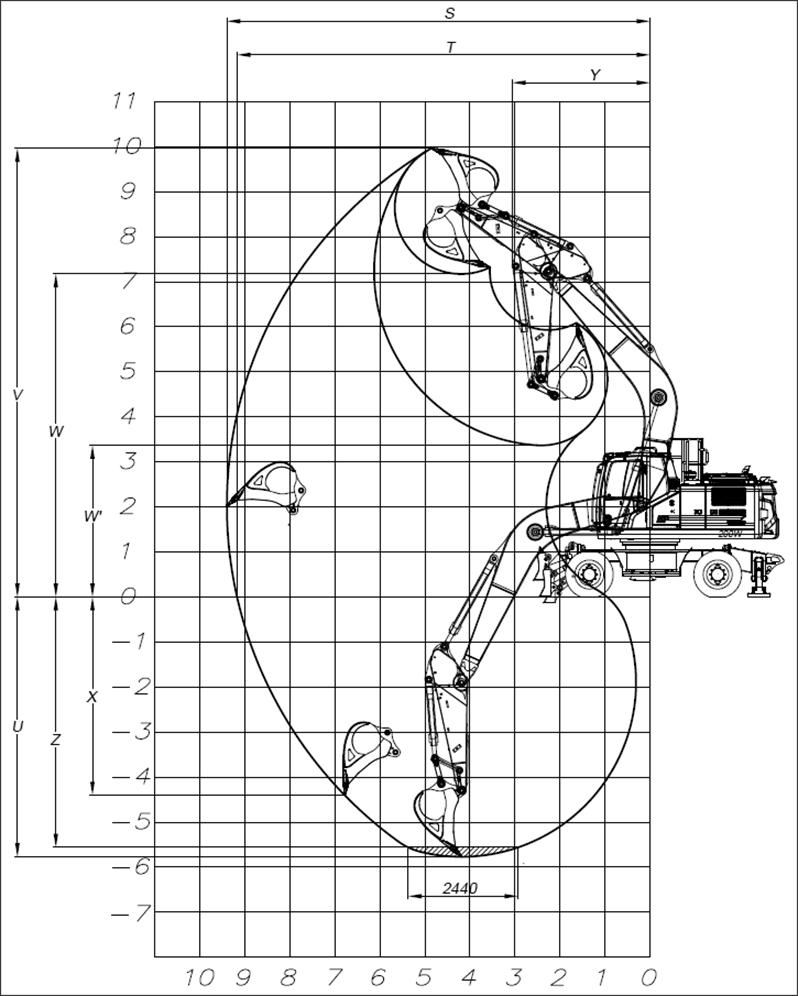
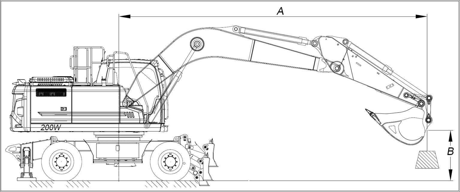
WORKING RANGE (NORMAL BOOM)
WORKING DIMENSIONS, mm
TECHNICAL SPECIFICATIONS OF HMK 210 W-4
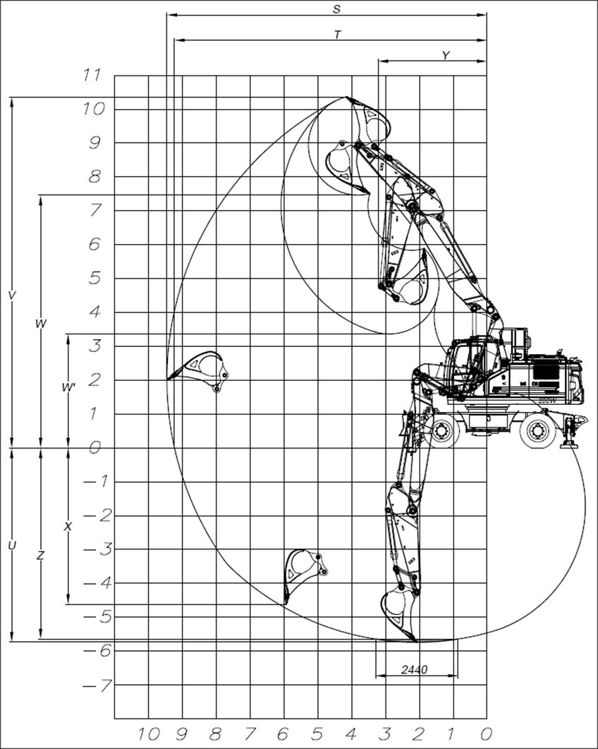
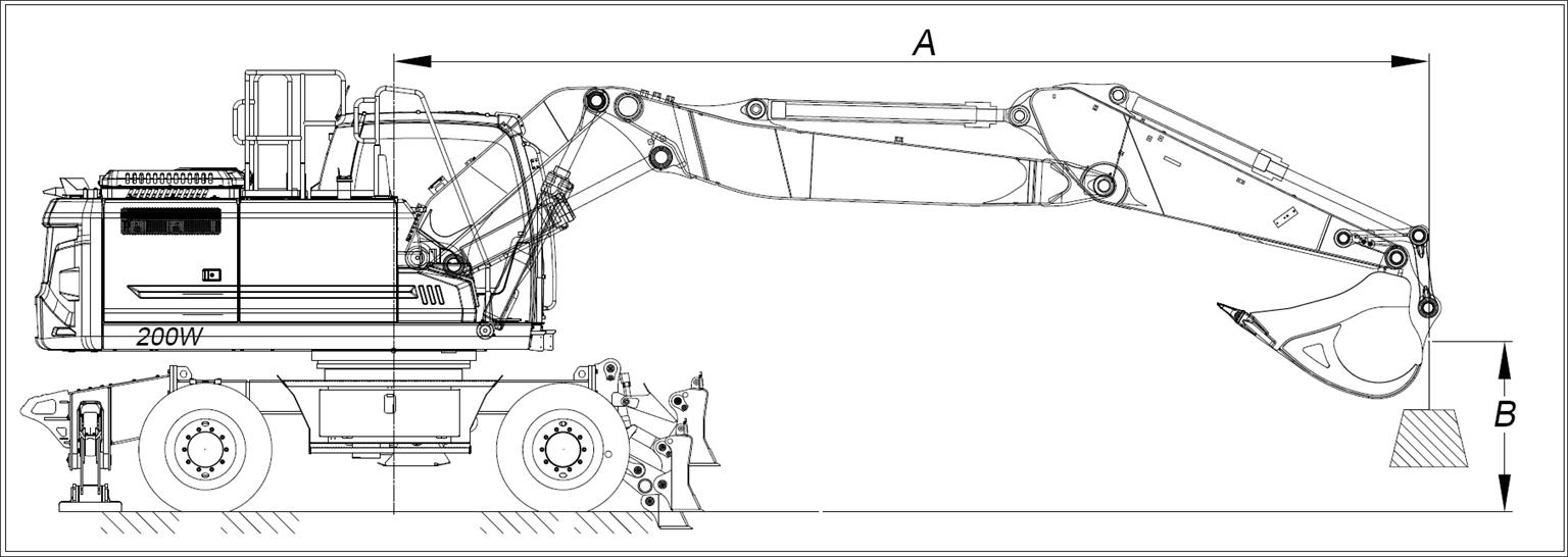
WORKING RANGE (ARTICULATED BOOM)
WORKING DIMENSIONS, mm
TECHNICAL SPECIFICATIONS OF HMK 210 W-4
SOUND AND VIBRATION LEVELS
Sound Level
Sound pressure level (LpA) inside the cab and sound power level (LwA) around the machine comply with 2000/14/EC.
Sound pressure level (LpA) inside the cab: dB (tested based on ISO 6396)
Sound power level (LwA) around the machine: ....... dB (tested based on ISO 6395)
Vibration Level
Declared vibration emission values in accordance with EN 12096 are as in the following.
Hand/arm vibration emission value is less than ...... m/s2 .
Whole body vibration emission value is less than m/s2
Hand/arm and whole body vibration emission values are determined in accordance with EN 1032:2008.
Seat vibration level is determined in accordance with EN ISO 7096.
WARNING
Vibration levels change with various operating conditions such as working mode, structure of ground, speed etc. Do the following tips to minimize the level of vibration emission and to reduce risks. Adjust the operator’s seat according to the operator’s weight.
Make sure that the suspension on various systems of the machine such as the cabin, the tire, the seat are maintained regularly.
Check the hydraulic system and the linkages regularly.
To the extent possible, do not steer, brake, accelerate, shift gears too suddenly; operate the attachments or load the bucket smoothly.
Slow down when traveling on a rough terrain.
TECHNICAL SPECIFICATIONS OF HMK 210 W-4
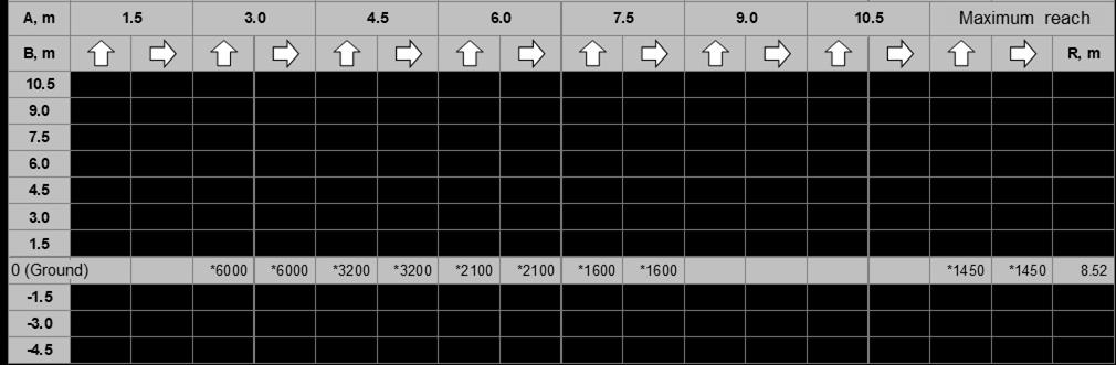
Lifting Capacity
WARNING
Do not exceed the capacity given on the table of lifting capacities posted on the Cabin window. For a safe operation, be sure that the working ground is level and has adequate supporting surface. Do not lift maximum loads given on lifting capacity table when working on non-level, soft and sandy terrain. Otherwise serious accidents may occur.
See the precautions for security given in the Parts 7.7 and 12.13.
Lifting capacities comply with SAE J1097 and ISO 10567. The load point is the load tying point on the bucket.
Lifting capacity do not exceed 87% of hydraulic capacity or %75 of tipping capacity. Bucket weight is excluded in given loads.
(*) Load is limited by hydraulic capacity rather than tipping capacity. Lifting capacities are to be considered for a machine working on a level and firm supporting ground.
Mono Boom
Boom: 5.6 m, Arm 2.4 m, Bucket 0.9 m3, Front dozer and rear outrigger, Counterweight: 3800 kg

: Front attachment is on the forward position.
: Front attachment is turned to the side position.
TECHNICAL SPECIFICATIONS OF HMK 210 W-4
Boom: 5.6 m, Arm 2.92 m, Bucket 0.9 m3, Front dozer and rear outrigger, Counterweight: 3800 kg

: Front attachment is on the forward position.
: Front attachment is turned to the side position.
Articulated Boom
Boom: 5.5 m, Arm 2.4 m, Bucket 0.9 m3, Front dozer and rear outrigger, Counterweight: 3800 kg

: Front attachment is on the forward position.
: Front attachment is turned to the side position.
TECHNICAL SPECIFICATIONS OF HMK 210 W-4
Boom: 5.5 m, Arm 2.92 m, Bucket 0.9 m3, Front dozer and rear outrigger, Counterweight: 3800 kg
: Front attachment is on the forward position.
: Front attachment is turned to the side position.
8. EQUIPMENT AND ATTACHMENTS


8.1. GENERAL PRECAUTIONS
Please use attachments that are supplied or recommended by HİDROMEK. Otherwise the performance and service life of the machine may be affected and safety related problems may arise. If you want to use any other attachment that is not specified in this manual, contact your authorized HİDROMEK dealer or Hidromek Services. Otherwise, possible problems regarding safety and/or performance will be considered as the users own responsibility.
WARNING
Take special care during removing and mounting operations. Make sure to take the following precautions when removing and mounting the work equipment.
Removing and mounting the work equipment should be done on a level and firm surface. When a second person is signaling the operator, both parties mustmake sure that theyunderstand each other without any doubt. For heavy objects, use a crane.
Before removing a heavypart, make sure to block it securely. Be careful of the center of gravity for heavy objects.
Support all lifted parts when working. When removing or mounting the work equipment put it down firmly.
When lifting by a crane or working near lifted attachments, never stand under the lifted object. Be sure to keep away from the lifted object.
WARNING
The crane operation should be done by qualified people who possess an operator license for the equipment he is using. DO NOT let any nonqualified persons to operate it. Refer to assembly-disassembly instructions or consult an authorized HİDROMEK dealer for the removing and mounting works.
8.2. CAUTION WHEN FITTING THE WORKING EQUIPMENT
WARNING
A long-length attachment will reduce the stability of the machine, so when swinging it on a slope, it may overturn due to unbalance. The following operations are very dangerous. Never perform the following: Do not descend with raised equipment.
Do not swing on a slope. If such operations have to be carried out, pile soil to make platform on the slope so that the machine can be kept horizontal when operating.
When a heavy attachment is fitted, swing flow becomes large (the distance from swing start position to swing stop position). Pay special attention to working area. Self-lowering may be increased.
Abnormal attached boom or arm can cause serious damage. Contact the authorized HİDROMEK dealer.
In case of being equipped with a long-length attachment, the work scope becomes large. Pay special attention not to hit against other things due to wrong judgment. In this time, keep sufficient distance from other things.
8.3. SELECTION OF ATTACHMENT
There are very important considerations when choosing and using the attachments. So obey the rules that are specified in this part.
IMPORTANT
Select an attachment suitable for the machine. Attachments that can be used are different from machine to machine. While selecting the attachments, contact your HIDROMEK Authorized Service or Dealer.
8.4. PROTECTION AGAINST FALLING OR FLYING OBJECTS (FOPS)
Install protective guards as required by the working conditions where the operator’s cab is subjected to falling or scattering materials.
When operating a breaker, make sure that you close the front window.
During operation, make sure all personnel are out of range of materials, which may fly off.
IMPORTANT
For protection guards and structures, contact with HIDROMEK Authorized Service or Dealer
Install protective cage when working with a breaker.
Install FOPS (Falling Object Protection Structure) where falling or scattering materials may damage the operator’s cab.
Install falling object guard (FOG) when working at quarries and demolition.
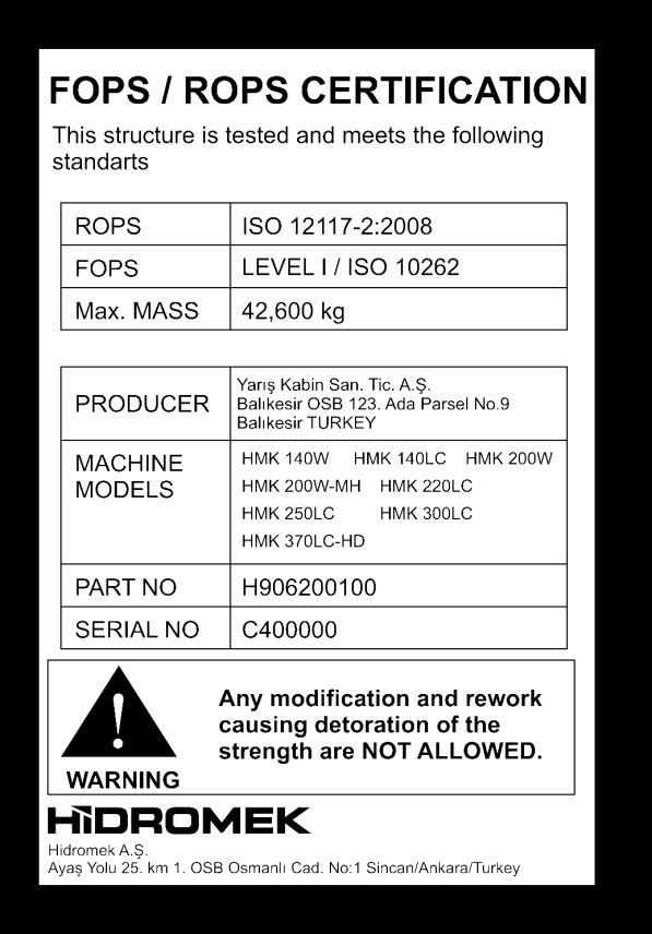
8.5. PROTECTION AGAINST TIPPING AND ROLLING OVER
Operator's cab name plate is hanged inside the operator's cab on the left hand side. Check the name plate to find out if the operator's cab has necessary protection against ROPS (Rolling Over Protection System), FOPS (Falling Over Protection System) or TOPS (Tipping Over Protection System).
DANGER
During working at construction sites where high risk of rolling over exist, like hillsides or slopes, be sure to have an operator's cab compatible with ROPS.
Consult with Hidromek Authorized Service to learn if your operator's cab protection fulfills your machine's operating conditions.
The decal below shows that the operator's cab is compatible with ROPS:
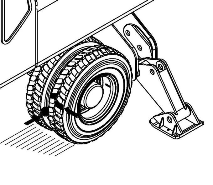
8.6. HANDLING TIRES
8.6.1. TIRE CHANGING PROCEDURE
Caution
Before changing tires, move safety lock lever to locked position. Place a warning tag on controls so that no one begins to operate machine while tires are being changed.
1. Park machine on secure and level ground able to support weight of machine.
2. Raise the carrier with the dozer blade and stabilizer to lift the tire off the ground.
3. Put blocks under the front axle and the rear axle.
4. Lower bucket to ground.
5. Remove wheel nuts (1) and outer tire assembly (2) from hub (3). Examine nuts and washers for wear and damage. Replace if necessary.
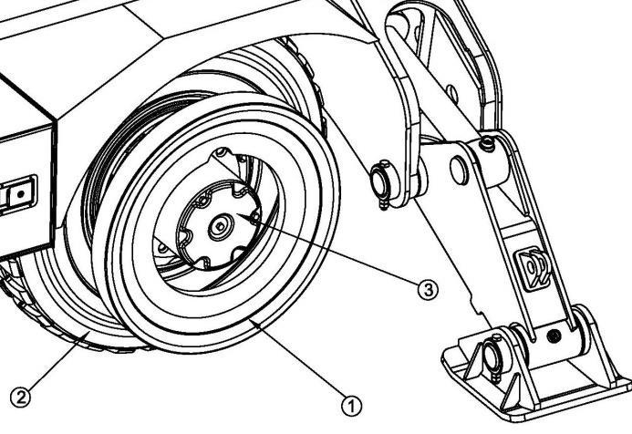
7. Remove inner washers from studs and examine for damage and wear.
8. Examine all parts for excessive wear and damage. Replace all necessary parts.
9. Reassemble parts in following order:
Inner washer
Inner tire
Rubber spacer
Outer tire
Outer washer and wheel nuts
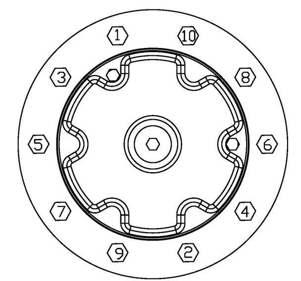
10. Use tightening pattern in figure when tightening wheel nuts.
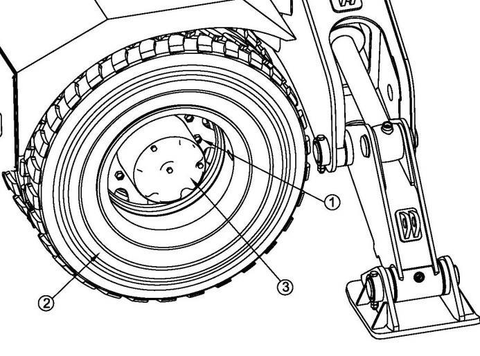
6. Remove rubber spacer (1) and inner tire assembly (2) from hub (3). Examine rubber spacer assembly for wear and damage. Replace if necessary.
11. Run machine forward and backward several times to ensure proper assembly and seating of the washers. Retighten wheel nuts to ensure proper torque.
Refer to Chapter 7. Specifications for tire pressure and wheel nut torque.
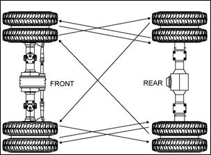
8.6.2. TIRE ROTATION
The wear differently depends on their positions. Therefore, change the mounting position periodically as shown.
8.7. HYDRAULIC BREAKER

Hydraulic breaker should be compatible with the pressure and flow settings of the excavator’s hydraulic system and it wouldn’t disturb balance of the machine. Use only Hidromek approved hydraulic breakers. Contact Hidromek Authorized Dealer to help you in choosing the right hydraulic breaker.
DANGER
As it may cause accidents do not operate hydraulic breaker valves when hydraulic system is under pressure.
Before operating hydraulic breaker valves stop the machine and release the pressure in hydraulic lines.
8.7.1. MAINLY AVAILABLE WORKS
Press the chisel firmly onto the surface at right angle.
1) Breaking stone and rock
2) Demolition work
3) Road repairing
It is widely used in works such as demolition of building, breaking road surfaces, tunneling work, smashing slag, and breaking or cutting stone.

WARNING
If the excavator will be charged in tunneling work, it should have suitable equipment and attachments. In tunneling work hydraulic breaker bracket should be chosen as tunnel type and a Hidromek approved hydraulic breaker should be used. Attachments like boom, arm, hydraulic breaker, hydraulic breaker bracket etc. should only be used after having Hidromek’s written approval or otherwise Hidromek will not be held liable for any failure, loss or damage.
When striking, press the chisel firmly onto the surface, and lift the frame about 5 cm. Never raise the machine unnecessarily high.
If the surface is repeatedly struck but it is not broken within 1 minute, move the breaker to break from the end portion.

The striking direction of chisel and the direction of breaker body are a little deviated. Correct the bucket cylinder so that the direction is always aligned.

Pushing the stones and rocks to move them
Press the chisel properly so blank striking does not occur.
Do not work by swing force.
8.7.2. INCORRECT METHODS
The following methods are prohibited in order to extend the service life of the machine and to work safely.


Never operate the cylinder to its stroke end, leave about 5 cm.
Moving the chisel while striking.
Striking horizontally, or in upward direction.


Twisting the chisel to make a hole in the ground.

Hammering with the breaker.
Raising the machine while the bucket cylinder is fully extended.
Do not operate the breaker to the side of the machine as the machine may tip over on a side and reduce undercarriage component life.


8.7.3. MAINTENANCE FOR HYDRAULIC BREAKER
Maintenance for machine operated with hydraulic breaker is different from maintenance for machine operated in normal working conditions, because the viscosity breakdown and contamination of hydraulic oil is faster. Determine replacement intervals for hydraulic oil, hydraulic oil return filter element and hydraulic breaker return filter element (if exists) according to the following table. Replace the hydraulic breaker return filter element according to hydraulic breaker operating hours.
Hydraulic Oil, Hydraulic Return Filter Element Replacement Intervals
Hydraulic oil
Hydraulic Oil Return Filter Element
HYDRAULİC BREAKER OPERATION RATE (%)
Replace Hydraulic Breaker Return Filter every 250 hydraulic breaker operating hour.
CAUTION
If the machine is used particularly in a dusty or dirty environment like tunnel, quarry, etc. replace the hydraulic breaker return filter (if exists) more frequently than stated above. Check the hydraulic oil to determine the filter replacement interval.
8.8. QUICK COUPLING ATTACHMENT
Quick coupling attachment is equipped with a double effect cylinder. Attachment has a fixed and a swivel jaw in order to engage bucket from bucket pins. Swivel jaw can swing in and out in connection with hydraulic cylinder. To fix swivel jaw, it has to be moved to the inside.
8.8.1. MOUNTING THE BUCKET
Operate the machine and bucket to such a position that the bucket looks to the cab on a straight ground.
Operate the quick coupling attachment to such a position that fixed jaw engages the first pin of the bucket.
Press the quick coupling attachment switch on the right hand side console continuously to open the swivel jaw.
Operate the arm by joystick to such a position that swivel jaw engages the second pin of bucket.
As you release your finger from the switch, jaw moves upwards and engages with the bucket pin.
Reinstall the safety pin to prevent possibility of accidental disengagement of the bucket from the attachment.
8.8.2. DISMOUNTING THE BUCKET
Park the machine on a level ground and rest the bucket on the floor. Remove the safety pin. Press the switch continuously on the right hand side console. While you are pressing, swivel jaw will move downward and bucket pin will be freed.
Caution
Be sure that safety pin and hydraulic system work smooth after installation of the bucket. Otherwise bucket may disengage from the attachment and this can cause an accidents.
WARNING
Before operating the machine be sure that red safety pin is installed on the quick coupling. Otherwise it may cause quick coupling hydraulic valve to be damaged.
WARNING
Be sure that there is no one in the working area of quick coupling attachment installation and adjusting.


