32 minute read
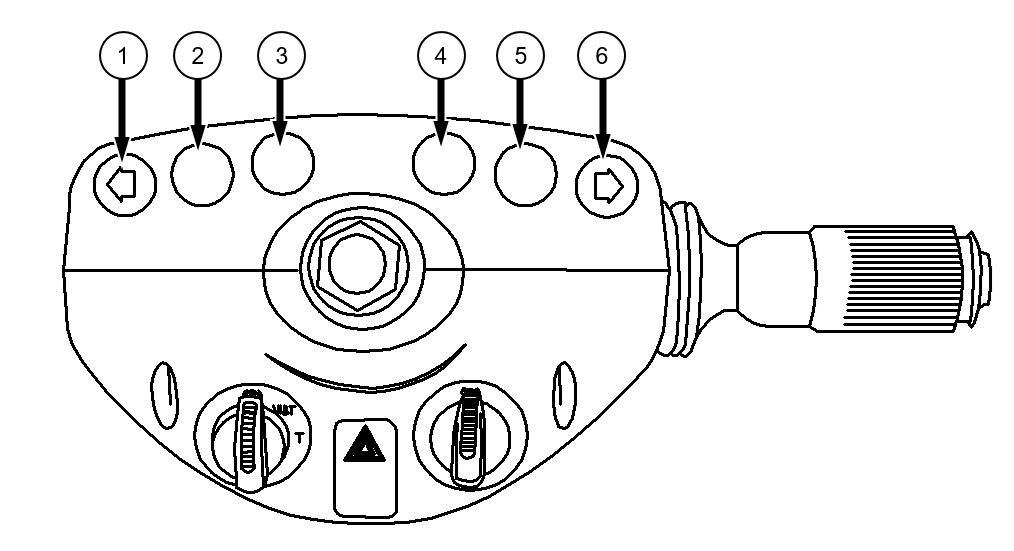
3.16.2. INDICATOR LIGHTS


1. Turn Signal Indicator Light (Left) Indicator light flashes when multi-function lever is pulled backward
4. Axle Lock Indicator Light Indicator light comes on steady when axle lock switch is off If you press the axle lock switch on the opera instrument panel, this light goes off.
3. Brake System Failure Indicator Light Indicator light comes on and buzzer sounds when brake charge pressure is below than required. At the same time “Low Brake Pressure” message comes on the display panel.
5. Flashing Headlight Indicator Light Indicator light comes on when multi-function lever is lifted up half.
6. Turn Signal Indicator Light (Right) Indicator light flashes when multi-function lever is pushed forward.
SPEED CHANGE
There are two speeds available in both forward and reverse. Push the upper side of the switch to select the first gear. Push the lower side of the switch to select the second gear.
Forward or reverse direction is selected by using the 3-position switch behind the Joystick.
DRIVING
Push the upper side of the switch to move forward and machine will move forward.
NEUTRAL POSITION
Center position (N position) of this switch is neutral position.

DRIVING BACKWARD
Push the lower side of the switch to move backwards and machine will move backwards.
Warning
Ensure that the FNR switch is in neutral position and engine is running at idle whenever the machine is stopped. Before changing forward or reverse direction, first stop the machine. When using the drive control switch, pay attention and check the direction of lower frame.
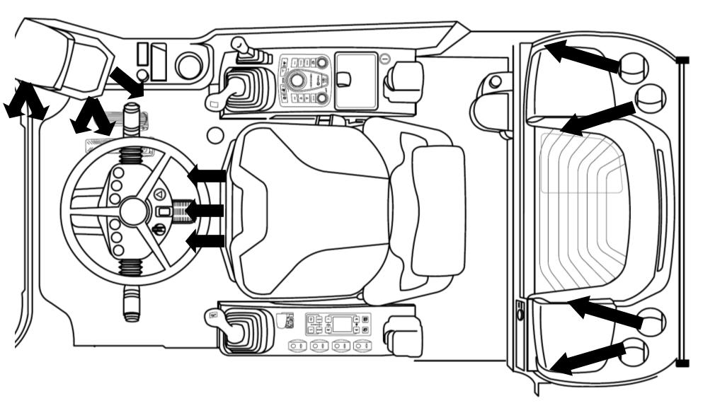
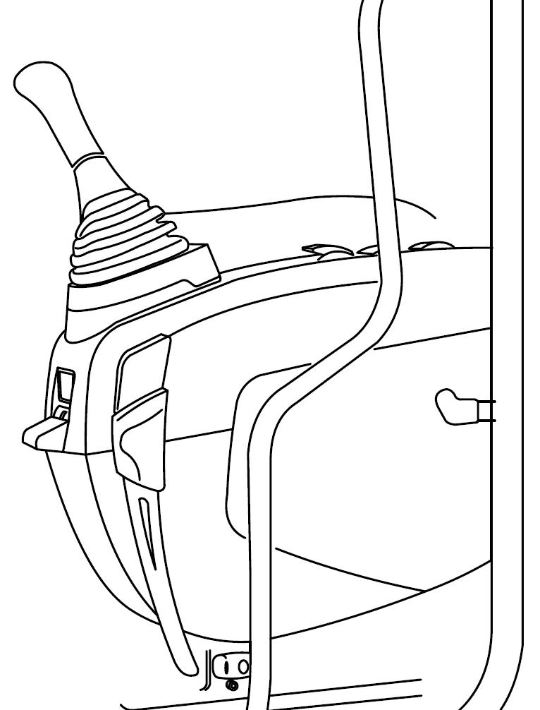
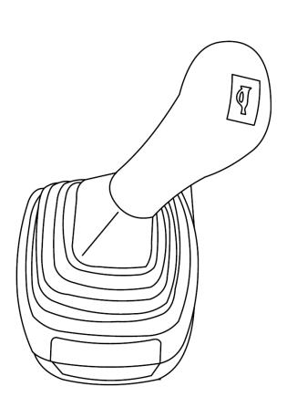
3.16.5. MULTI-FUNCTION LEVER
It is located on the right hand side of the steering column. Switches on lever and their functions are as follows.
RIGHT TURN SIGNAL
To signal a right turn, pull the lever backward. Push the lever forward to turn off the signal.
LEFT TURN SIGNAL
To signal a left turn, push the lever forward. Pull the lever backward to turn off the signal.
FLASHING HEADLIGHTS
Headlights flash when the lever lifted up half.
HIGH BEAM
High beam of headlights is “ON” when the lever is lifted up complete. If the same operation is repeated, high beam headlights will “OFF”.
Caution
Low beam of headlights should be used when driving on public roads in order not to disturb other drivers for safety in traffic. High beam of headlights may disturb the eyes of other drivers and may cause fatal accidents.
HORN
Push the button on the top end of the lever to switch the horn on.
Continuous Windscreen Wiper
"0" Position : Wiper doesn't operate.
"I" Position : When barrel is turned in forward direction wiper operates continuously in slow mode.
"II" Position : When barrel is turned in forward direction again wiper operates continuously in fast mode.
Windscreen Washer
Pull barrel to the steering column to spray water on the windscreen. Windscreen washer button is around the horn button.
Caution
Make sure that there is sufficient amount of washer fluid in the washer reservoir before operating the washer.
Windscreen washer reservoir
Intermittent Windscreen Wiper
"0" Position : Wiper doesn't operate.
"J" Position : When barrel is turned in backward direction wiper operates intermittently.
Switch is located on the left hand side of the steering column. This switch has 3 positions. Positions and their functions are as in the following:
PARK MODE
Select “P” mode, when the machine is in park mode. In this position parking brake is applied. At this position attachment operation and travel operation are not available.
WORK
And Travel Mode
Select “W&T” mode for travel and operation. At this position, do not use Cruise (CR) function. The parking brake is released.
TRAVEL MODE
Select “T” mode, when machine travels without doing operation. Attachment operation is unavailable. CR function is available in this mode. The parking brake is released.
2. Hazard Warning Light Switch
This switch is used to inform emergency to the others during the operating and urgent parking. When this switch is operated, Flasher Hazard Warning Lights on.
1. Mode Selection Switch CAUTION
When the switch is in the “P” or “T” position the control levers are not functional. To avoid unexpected attachment operation, put the mode selection switch in “T” position. Although it is possible to travel with the “W&T” mode, exercise extreme caution since the front attachment will operate if the control lever is accidently touched.
3.17. SAFETY LOCKING DEVICE WARNING
The SAFETY LOCK LEVER must be pulled in LOCKED position to prevent machine controls from an accidental movement. The operator must lock the safety lever before he leaves the operator’s seat and especially during maintenance and repair work unless it is necessary to operate the machine for this purpose. The hydraulic system is disabled to function even though the levers can be moved.
If not, an accidental movement of any control lever will cause the machine or an attachment to move, and will cause serious injury or death. When the safety lock lever is at straight position, the safety locking system is UNLOCKED. Make sure to rotate the safety lock lever down to correctly engage the LOCKED position. Do not use the control levers to get on and off the machine, the machine may suddenly operate and cause serious injury or death.
This system is used to stop the attachment, swing and travel unit. Pull the safety-locking lever equipped on the left control console to lock out the hydraulic control levers. The control levers and travel pedals (levers) are available to move even in the hydraulic "LOCKED" position.
3.18. ADJUSTING ARMREST HEIGHT
Height of the right and left armrests can be adjusted independently There is a star knob at the back of the armrest Turn the star knob to the left. With the aid of the spring armrest will be moved to the top upper position. Press the armrest down and set it to the desired position then tighten the star knob by turning it to the right.
3.19. ARMREST ANGLE ADJUSTMENT
The inclination of the armrests can be modified by turning the adjustment knob. Adjust the armrest to the desired position.
3.20. CONSOLE ANGLE ADJUSTING LEVERS
Angle of the consoles can be adjusted independently by levers at the front Hold the lever with one hand and hold the console with other hand.
Console can be locked at 3 different positions. Adjust the best position and release the lever.
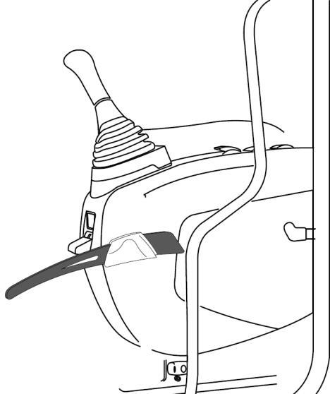
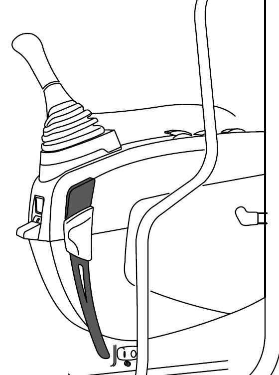
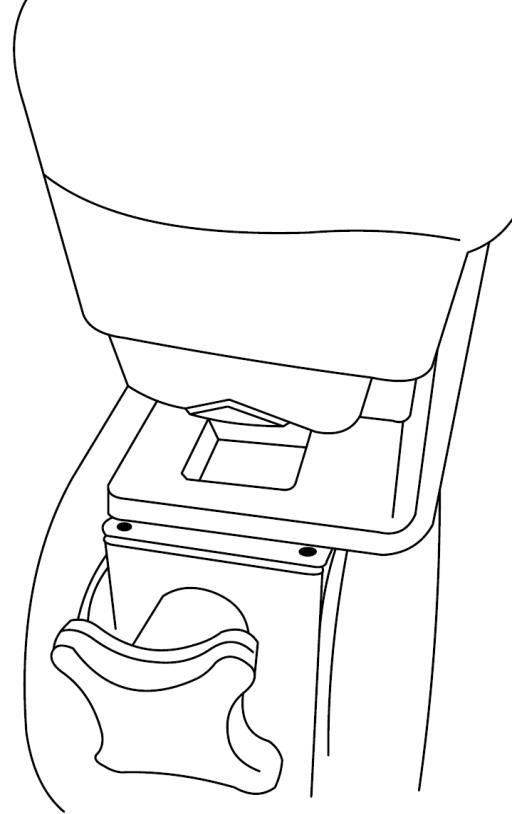
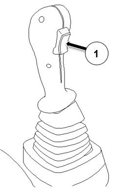
3.21. LEFT CONSOLE LIFTING LEVER
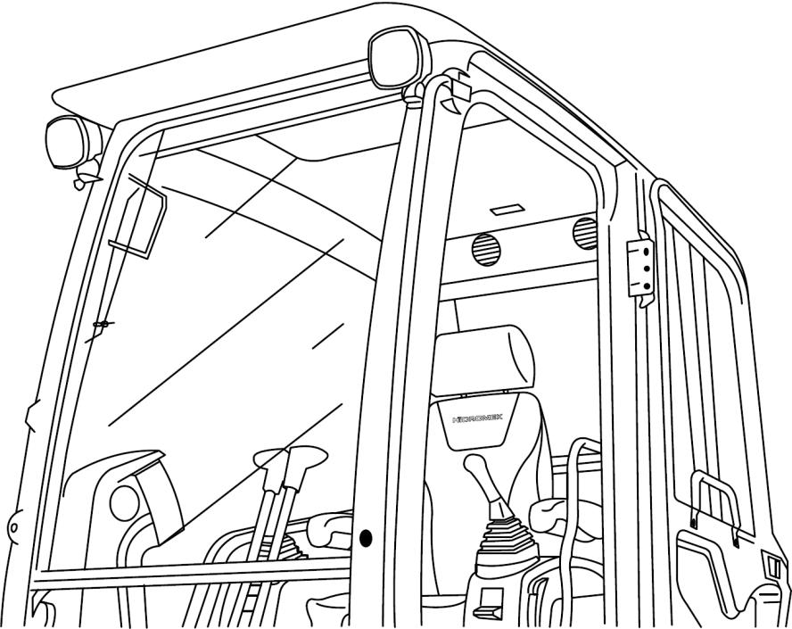
Left console lifting lever is at the back of the left joystick. It is used to provide more space when getting in and out of the operator's cab. After lifting left console all operating and travel levers gets locked even though the safety locking device is in unlocked position. To lift the console pull the lever (1) while sitting on the operator's seat. Console will move from position 1 to position 2.
3.22. LEVERS
3.22.1. OPERATING LEVERS
■ LEFT OPERATING LEVER
This lever controls swing and arm operations. The horn button is located on this lever.
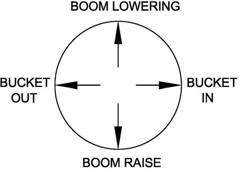
■ RIGHT OPERATING LEVER

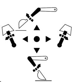
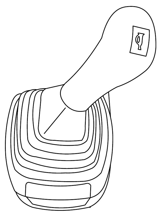
This lever controls the boom and the bucket operations.
There is an optional attachment switch on it.
1. Rotator proportional control (optional)
2. Rotator right turn (optional)
3. Rotator left turn (optional) proportional control (optional)


4.
(optional)
6. Shear close (optional)
FNR (forward reverse direction selection switch)
3.23. SWING LOCK
Before travelling the machine, applythe swing lock. Otherwise swing direction will change according to the probable failure and cause dangerous accidents while traveling.
Caution
Push lock pin down while traveling. Otherwise dangerous accidents can occur.
(ELECTRO-HYDRAULIC SWING LOCK)
Swing lock button (6) is located on the right console. Use the button to hydraulically lock the upper chassis to lower chassis
When upper side of the button is pressed swing motor brake is applied. When lower side of the button is pressed swing motor brake is released. Follow the procedure below to apply swing lock:
1. Swing the upper chassis and align it with lower chassis.
2. Push the swing lock button.
3. Wait for 3 seconds without controlling the attachments.
4. If upper chassis and lower chassis was not aligned to each other, in the control panel a red lamp comes on and "upper chassis is not centered" message appears. Release the swing lock and align the upper chassis with lower chassis until green lamp comes on in the control panel. Then press the button to apply the swing lock.
5. When swing lock is applied symbol comes on in the control panel.
Follow the procedure below to release swing lock:
1. Press the swing lock button.
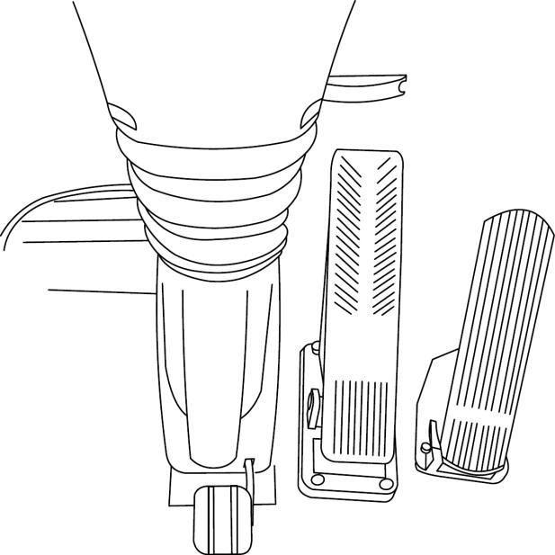
3.24. ACCELERATOR AND BRAKE PEDALS
3.24.1.
Accelerator Pedal
This pedal is located on the right hand side of the steering console. The accelerator pedal controls the engine speed for traveling
When this pedal is depressed during the Speed Selection Switch is at 1st step either forward or reverse, the machine will start off. Machine traveling speed increase or decrease according to the amount of the pedal is depressed.
3.24.2. BRAKE PEDAL
This pedal is located on the right hand side of the steering console.
Brake pedal operates the brake system. When the pedal is pressed to its maximum position, it will lock into position. To release the brake pedal from the locked position, press down on the release pedal. It is used to slow down and stop the machine.
Caution
If upper body is turned 180, the machine is handled in the opposite direction of the forward and reverse. Therefore, before depressing the pedal, confirm the direction of the upper body.
Warning
Prior to excavating depress the brake pedal and engage the latch mechanism to lock the service brake in the applied position. If parking brake has been manually released do not rely on the locked service brakes to hold the machine.
For safety and protection of brake system, lower the dozer blade and stabilizer to the ground and support the machine before working. Do not use the service brakes unnecessarily since over-heating could occur, causing brake performance to deteriorate.
When finishing work or parking the machine always releases the service brake pedal. Before starting work, always check the performance of the service brakes.
The service brake is used to prevent the machine from being pulled or pushed when excavating. The service brake is locked and released by latch as shown in figure.
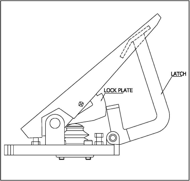
When working, lock the service brake.
Emergency Braking:
At a service brake failure, the braking effect of the hydrostatic drive is also additionally acting. This braking is not adjustable and cannot be influenced by the operator.
3.24.3. BRAKE SYSTEM TEST PROCEDURE
• Start the engine and select power mode “P”.
• Run the engine for about 5-10 minutes to warmup and stop the engine.
• Turn the ignition key to “ON” position without starting engine.
• "Brake pressure low" warning light must not come ON. In this mode press the brake pedal fully and release. Repeat the process several times with some waiting periods between pedal operations. Pedal must be pressed at least 3 times before the "brake pressure low" warning light comes ON. If not, the accumulator may be faulty. Do not move the machine and call Hidromek Authorized Service for help.
Warning
Do not operate a machine whose brakes are faulty.
All maintenance and repair works on the brake system must be performed only by an authorized Hidromek service.
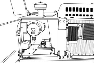
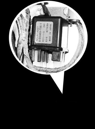
3.25. FUSE / RELAY BOX
Fuses are equipped to protect the electric system from an electrical overload. Fuse box cover is under the mat of convenient storage.
Important
When replacing fuses, make sure to turn the starter key to “stop” (OFF) position. When replacing fuses, ensure that they are of the same capacity.
Replacement Method
Open the cover placed at heater cover. Remove the burnt fuse using a fuse holder tool. Install a new fuse, which has the same capacity as the old one.
Placement of fuses and relays is shown in the figure.


3.26. AUTOMATIC/MANUAL MODE SWITCH
Should the instrument panel fail to work, press manual switch to operate the system in manual mode. In this mode machine electronic control unit is deactivated and engine speed can be set by throttle control dial manually.

WARNING
Use manual mode only in emergency situations to move the machine out of the danger zone. Do not operate attachments in this mode. Consult HIDROMEK AUTHORIZED SERVICE to have the problem fixed as soon as possible.
WARNING
Operating the engine in manual mode stops the after treatment functioning and will cause severe damage to the exhaust system components: DPD, DOC, SCR.
3.27. BATTERY RELAY
Battery relay is located under the air filter. When the operator stops the engine, it will automatically cut off the circuit after 7-8 seconds and an audio warning will be heard.
It will automatically cut the power off in case of an electrical short circuit or overload. This will prevent the electric wiring and components from burning or damage.
3.28. BATTERY MASTER SWITCH

Caution
"Start" is available only when the master switch is at "ON" position. When checking electric system or parking the machine, ensure that the master switch is at "OFF" position for safety and to prevent battery discharge. Never put the master switch at "OFF" position while running the engine. In case of cut off, battery can't be charged or malfunction of electric system may occur.
The battery master switch is installed inside the toolbox located at the right hand side of the machine.
ON Position: Turn the key clockwise to supply power to the electrical system.
OFF Position: Turn the keycounter clockwise to cut off electric power to the machine.
When battery disconnect switch is set in OFF position, running engine will be stopped. Use this switch in case of an emergency.
Allow 10 minutes after the engine has stopped before you turn the battery disconnect switch off.
Systems such as the engine controller (ECM) and SCR controller (DCU) continue to operate for approximately 10 minutes after the engine is stopped. This systems may malfunction if the battery power is turned off while these systems are still operating.
Disconnecting the battery power too soon may prevent cooling of the DEF/AdBlue® system and purging of the (DEF/AdBlue®) lines after the engine is shut down. Not allowing the DEF/AdBlue® system to be cooled can damage the system. Not allowing the DEF/AdBlue® purge to be performed can damage the DEF/AdBlue® system.
To restart the engine, set battery disconnect switch in ON position, then turn the starting switch key to START position.
1.
Figure. Battery master switch
3.29. HEATER AND AIR CONDITION
HEATER AND AIR CONDITIONER VENTS
3.29.1. CONTROL UNIT
The air conditioner installed in your machine is automatic. The automatic air conditioner is controlled through the air conditioner control panel which is on the left console in the operator cabinet. The condition of the air conditioner system can be monitored easily via the lamps on the buttons of the climate control panel.
1. Power button
2. Defroster button
5.
6.
7.
8.

9. “Blower speed selection button” / “Air conditioner automatic mode ON/OFF” button control button” / “Air conditioner ON/OFF” button
10.
5.
The lamp on the button lights up and the indoor recirculation mode is activated when this button is pressed. Air can not enter the operator’s cab from outside. Blower circulates the air inside the operator’s cab. This function is used particularly in dusty environments.
The outside air intake mode is activated when the button is pressed again. In this mode blower draws in the outdoor air and circulates it in the cabin.
7. Face/Rear vent button: Press this button to direct the blowed air from the front and back vents of the operator’s cab
8. Foot vent button: Press this button to direct the blowed air from the foot vents of the operator’s cab
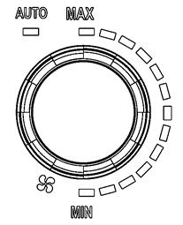
9. “Blower speed selection button” / “Air conditioner automatic mode ON/OFF” button:
Increasing blower speed: Turn the button to the left for increasing the blower fan speed. Adjusted level is indicated by the lamps around the button.
Decreasing blower speed: Turn the button to the right for decreasing the blower fan speed. Adjusted level is indicated by the lamps around the button.
Air conditioner automatic mode: Press the button to switch ON or OFF the air conditioner automatic mode. In automatic mode, air conditioner automatically adjusts the open vents, blown air temperature and fan speed with respect to the temperature inside the operator’s cab.
10. “Temperature control button” / “Air conditionerON/OFF”button
Increasing temperature: Turn the button to the right to increase the temperature of the blown air. Adjusted air temperature is indicated by the lamps around the button.
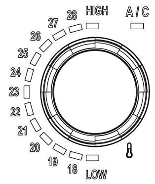
Decreasing temperature: Turn the button to the left to decrease the temperature of the blown air. Adjusted air temperature is indicated by the lamps around the button.
Air conditioner ON/OFF: Press the button to start or stop the air conditioner.
3.30. LIGHTER
There is a Cigarette Lighter placed on the rear console. Press it down to start the heater; it will eject in a few seconds. When it returns to its initial position, it is ready to use.
DANGER
If the Cigarette Lighter does not eject, do not leave it pressed down. Remove the Cigarette Lighter and contact Hidromek Authorized Service.
Lighter socket can be used as a power supply for 24 Volt devices.
3.31. BOTTLE HOLDER
On the front side of rear console there is a bottle holder.
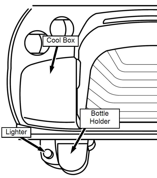
3.32. COOL BOX
It is possible to keep food and drinks cool in the cool box while A/C works.
3.33. CONVENIENT STORAGE AND CONVENIENT STORAGE BOX
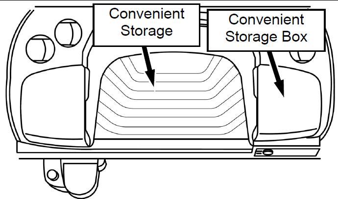
There is a convenient storage place and a storage box on the rear console.
3.34. EMERGENCY EXIT
The door and the rear window are the emergency exits of the operator's cab.
Take the emergency hammer from the pillar at the rear left hand side of the cab and break the windows.
Make available a first-aid kit and instruction booklet on the convenient storage place.
Display the names and telephone numbers of personnel to contact in case of an emergency.
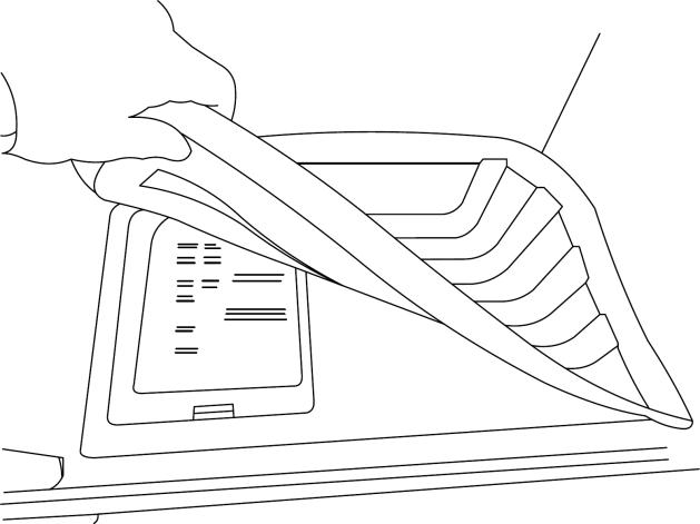
3.36. FRONT WINDSHIELD
Upper part of the window shield of the operator’s cab can be fully opened by sliding and parking it under the roof. Be careful and hold firmly when opening or closing the rear window as it is sliding.
Warning
The SAFETY LOCK LEVER must be pulled in LOCKED position to prevent machine controls from an accidental movement. The operator must lock the safety lever before he leaves the operator’s seat and especially during maintenance and repair work unless it is necessary to operate the machine for this purpose.
If not, an accidental movement of any control lever will cause the machine or an attachment to move, and will cause serious injury or death. When the safety lock lever is at straight position, the safety locking system is UNLOCKED. Make sure to rotate safety lock lever down to LOCKED position.
See Chapter 3.17. “SAFETY LOCKING DEVICE".
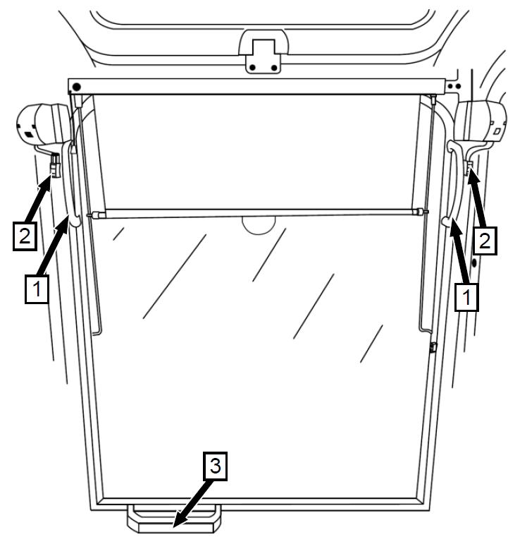
OPENING THE FRONT WINDSHIELD
A) Hold the handles (1) at each side so that the latches are against your pointing fingers
B) Pull to unlock the latches (2) Hold one of the side handle (1) and the bottom handle (3) and pull the windshield upwards and slide the windshield until it is latched under the roof in horizontal position.
C) After the windshield is stowed under the roof, check if the latches are secure and windshield is stable.
CLOSING THE FRONT WINDSHIELD
A) Hold one of the handles (1) and press the unlock latch (4) at the back side of the operator's cab
B) Windshield will move to the front by itself Move the windshield all the way to close it.
C) Windshield will become in vertical angle and it will lock into its place. Since the front windshield is heavy pay attention to stand in suitable position when sliding the windshield
3.37. DOOR
Press the latch of the door handle (1) and open the door
If the door is locked, unlock the door with the starter key (2).
Lock (2) the door with the key before leaving the machine.
Pull the latch (3) and push the door outside to open the door from inside the cab.
3.38. DOOR LOCK MECHANISM
It is used to keep the operators cab door in full open state.
Open the door and fully rotate 180 degrees until it snaps into the lock mechanism on the rear side of the cab.

Verify that it is securely fixed. Press the handle inside the operator’s cab to release the door.
3.39. SIDE WINDOW
Side window is on the left hand side of the operator's cab. This window may get opened to let air come in.
To open the rear side of the left window, press the latch with your thumb and slide the window forward.
To open the front side of the left window, press the latch with your thumb and slide the window backward.
3.40. FIRE EXTINGUISHER (OPTIONAL)
Fire extinguisher should be mounted on the right hand side rear panel of operator's cab.
Connect the fire extinguisher mounting bracket to the panel with its screws and place the fire extinguisher.
Make available a fire extinguisher, and read carefully the directions for use.
Display the measures to be taken in case of fire or accident.
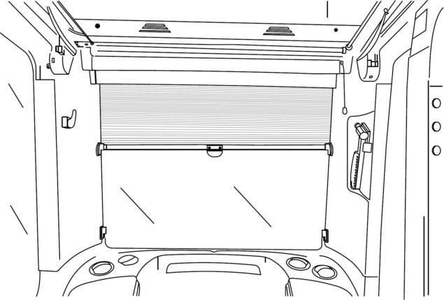
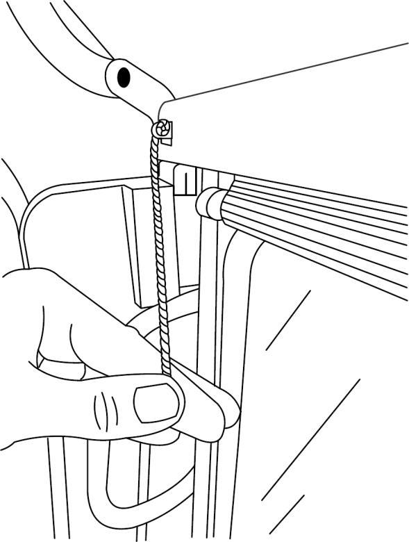
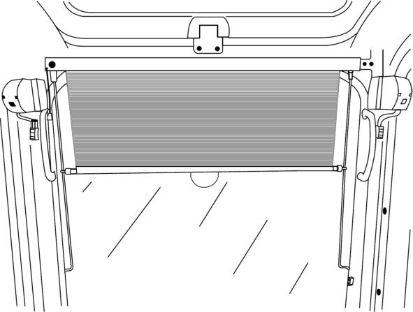
Front curtain mechanism is attached to the front windshield. Pull the front curtain down and leave it in the desired position. Pull the string on the left hand side of the curtain to roll the curtain back. When pulling the string with one hand, hold the curtain with other hand, adjust the curtain and releasing the string to lock the curtain.
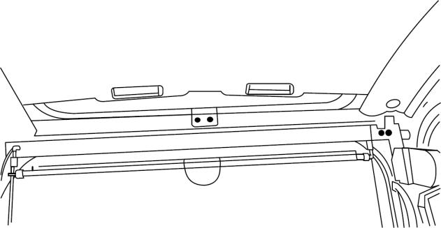
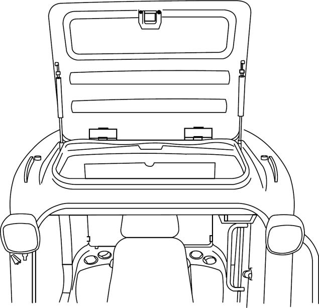
Unlock the latch and push the sunroof up to open.
3.43.
Shade under the sunroof can be opened to look up or let the sunlight in. backward by holding from its handles.
Interior light of the operator’s cabin is located on the rear side of the ceiling.
Switch of interior lightning has three positions.
1. Light is turned "OFF" Light turns "ON" when operator's cab door opens
2. Light is always turned "OFF".
3. Light is always turned "ON"
3.45.
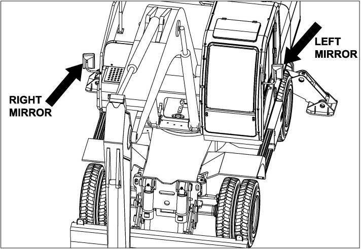
Adjust right and left mirror, so that the right and left side end of the machine can be seen on a part of mirrors.
3.46. OPERATOR’SSEATADJUSTMENT
Adjust operator’s seat before operating the machine to obtain the most comfortable position.
1.
Hold the headrest (1) with two hands and adjust the height and angle.

2.
Turn adjusting knob (2) until the indicated weight corresponds to your own weight.
DANGER
To prevent damage to health, the setting for the driver’s weight must be checked and adjusted as necessary before the vehicle is driven.
To adjust the depth of the seat cushion, lift the R/H handle (3). By moving the seat cushion backwards or forwards the desired seating position can be reached.
To adjust the angle of the seat pan, lift the L/H handle (4). By exerting pressure on or off the seat pan it can be moved to the desired angle position.
Adjust desired distance forward and backward using adjustment lever of seat distance (5). Lift the lever, slide the seat to desired position, and release it to fix.
DANGER
After setting the desired position try to move the seat and be sure that the locking lever is in its position. Otherwise the seat can move out of control and may cause severe injury.

6.
Adjust desired distance forward and backward using adjustment lever of seat base distance (6). Lift the lever, slide the seat to desired position, and release it to fix.
7.
Lift lever (7) to position the backrest at desired angle, and release the lever to fix.
DANGER
The locking lever must latch into the desired position. It should not be possible to move the backrest into another position when it is locked.
By turning the adjustment knob (8) to the left or right, both the height and curvature of the backrest cushion can be individually adjusted. This increases both the seating comfort and the performance of the driver.
9. Height adjustment


The seat height can be adjusted with several settings. Raise the driver seat to the required height until it audibly latches into place. When the seat is raised above the highest setting (end stop), it drops back down to the lowest position.
Warning
If there is any problem with your seat, call your service. Never try to fix it on your own.
3.47. SEAT BELT
Seatbelts must be fastened before driving.
Check the conditions of the seatbelt and its parts every time you get in the machine.
If it is worn or involved in an accident or used in any other situation that might cause tension on the seatbelt, or if its attaching parts (loosening, swinging etc.) are not correctly fit, do not operate the machine before the problem is fixed.
Replace the seatbelts every 3 years periodically even if they have no apparent problems.
Do not make, or allow anybody to make any modifications to the seatbelt and its parts. Seatbelts and their parts cannot be repaired. Replace them if necessary.
If it is necessary to clean the seatbelt, you can wash it with natural soap and water. Leave it dry outside of its box and put back in the box correctly.
3.47.1. FASTENING THE SEAT BELT
Adjust the operator’s seat to allow full travel lever stroke with operators back against the seat back.
After adjusting the seat, insert hook (2) into buckle (1). Pull them with both hands to check whether they are locked securely.
To remove the belt, push button (4) of buckle (1).
When removing the seatbelt, hold the seatbelt with your right hand and push the button with your left hand. Otherwise, the seatbelt may fly out and may cause unexpected accidents.
3.47.2. ADJUSTING LENGTH OF THE BELT
To lengthen, pull the belt by turning hook (2) to your body as illustrated.
To shorten, pull the free end of the belt at hook (2). Adjust the belt length suitable to your body and ensure the belt webbing is not twisted.
4.1. INSPECTIONS BEFORE STARTING THE ENGINE
For operator safety, comfortable operation and for an extended service life of the machine, keep track of the engine operation hours and the conditions of the machine parts during operation, and perform inspections at appropriate intervals, and provide maintenance works in accordance with the findings of the inspections. When an inspection reveals an abnormality or there was an abnormality found during operation in the previous day or time, have the machine repaired at a Hidromek Authorized Service before it is operated again. If checks and inspections are not performed, serious problems may occur.
Before operation check the following items every dayto ensure operator safetyand extended service life of the machine:
Caution
Before operating the machine, read and understand this Operation and Maintenance Manual thoroughly in order to use the machine effectively and safely. Keep this manual in the operator’s cab in the pocket beside the right hand side console for quick reference.
If the Operation and Maintenance Manual is lost or damaged, contact your Hidromek Authorized Dealer to order a new one.
Perform “Every 10 Hours inspection and maintenance” before daily operation of the machine.
Check under and around the machine and inspect for below items:
Open the right hand side door of the machine and check for below items:
1. Drain water from fuel filters
Open the left hand side door of the machine and check for below items:
1. Check looseness and corrosion on battery terminals
2. Check battery electrolyte level
3. Turn the battery switch to "ON" position.
Get into the operator’s cab and check for below items:
1. Check if the horn is operating.
2. Fasten seat belt. Check for proper functionality and condition.
Turn the starter key to “ON” position and check for below items:
1. Check engine failure indicators.
2. Check all warning lamps and indicators on the instrument panel.
3. Check the fuel level indicator.
4. Check the air filter clogged indicator on the instrument panel. If it is ON, immediately replace the air filter outer element. Replacing the air filter outer element ► Refer to Chapter 6.16.6. “Checking, changing, and if necessary cleaning air filter outer element”.
10. Check for loose terminal or connector, or open circuit in electrical wiring
11. Check for looseness of bolts or nuts, the leakage of oil, fuel, or coolant, and the condition of attachment or hydraulic system around and under the machine.
12. Check looseness of cables and connectors and dust on high temperature parts
13. Check fuel level
Climb to the machine, open the engine hood and check for below items:
1. Check engine oil level and contamination
2. Add engine oil if necessary
3. Check fan belt looseness and damage
4. Check coolant level from the coolant expansion tank
Figure. Air filter clogged indicator
5. Confirm that the engine emergency stop switch is turned "OFF" before starting the engine.
6. Before starting the engine, confirm that all controls are at neutral position and each switch such as windshield wiper, lighting, and air conditioner is turned off.
7. Ensure that if the left console is at the locked position.
Sound the horn, start the engine and check for below items:
1. Check engine starting condition and abnormal noise.
2. Check operation of lamps.
3. Check all warning lamps and indicators on the instrument panel.
4. Check attachment movements.
5. Depress switches to check whether head lights, working lamps and interior lamp light.
Sound the horn, travel the machine slowly and check for below items:
1. Check machine traveling speed.
Stop the engine and check for below items:
1. Check leakage of fuel, coolant and engine oil
4.2. STARTING THE ENGINE
4.2.1. STARTING AT NORMAL TEMPERATURE
WARNING
After checking for personnel and obstructions around the machine, sound the horn and start the engine.
WARNING
Do not keep the starter switch turned to “START” for 20 seconds or longer. Operating the starter for too long might cause battery failure or might result in overheating and even a fire. When starting the engine, make sure that no flammable material is present in the direction of exhaust outlet. If a flammable material is present, it is very dangerous because such material may be deformed, discolored or ignited, leading to a fire.
1. Place the accelerator, throttle and operation levers to the idling position.
CAUTION
Never operate the control levers and button switches when starting.
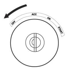
2. Turn the starter switch to the "ON" position. Also, when the preheat indicator light comes on, wait for 0 - 8 seconds until it turns off. This may not come on depending on the conditions.
CAUTION
Do not perform the starting operation while the preheat indicator light is on.
3. After confirming that the preheat indicator light has gone out, turn the starter switch to the "START" position to start the engine.
CAUTION
When an abnormal sound is heard from the starter motor, if the starting operation is continued, the starter motor can be burned out. After disconnecting the batterycables, charge the battery from an external power source. When the starting operation is performed repeatedly, starting the next motion without waiting for the starter motor to stop completely may damage or break the starter pinion and the engine ring gear.

Starter failure may occur if the engine is started when the battery has not been sufficiently charged.
5. When the engine is not started after the starting operating is performed repeatedly, an abnormality in the starting system can be suspected, so inspect the related parts.
CAUTION
Do not turn the starter switch to the "OFF" position while the engine is running. Depending on the machine on which the engine is installed, this may cause a failure such as a malfunction of meters and battery charging failure. Do not apply a starting aid to the intake system. This may damage the engine.
NOTE
In the cold season, when the engine is cold, the exhaust smoke (white smoke) may increase.
4. When the engine is not started with one operation, turn the battery and starter switch to "OFF". Have a break of 60 seconds or longer for starter functionality recovery and engine controller (ECM) communication process, and then perform the starting operation again.

6. After starting the engine, follow steps in “Warming Up”.
CAUTION
While the engine is running, the urea SCR system is purging, and immediately after operating, the exhaust piping is extremely hot. Make sure that there are no flammable items such as plants, dry grass, paper waste, oil, or old tires nearby. Take extra caution when operating the machine indoors.
Be careful of the exhaust gas heat generated while the engine is idling, and especially while the urea SCR system is purging.
4.2.2. STARTING IN COLD WEATHER
Before starting the engine, be sure to perform preheating. When it is difficult to start the engine, let it stand for a while to allow the batteryto recover, perform adequate preheating, and then start the engine.
Warning
After performing a safety check for people and obstructions around the machine, honk the horn and start the engine.
Insert the key into the starter switch and turn the key to ON position. Wait until the preheat indicator turns off, then, turn the key to START position.
As an engine starting aid, pre-heating is required in cold weather starting. This system allows to start easily in cold weather and to reduce white smoke and noise at starting. When turning key switch to ON, glow plugs will grow red-hot to pre-heat the engine. At this time, check pre-heat indicator, if it is OFF. Pre-heating time is about 1 to 15 seconds depending on engine coolant temperature.
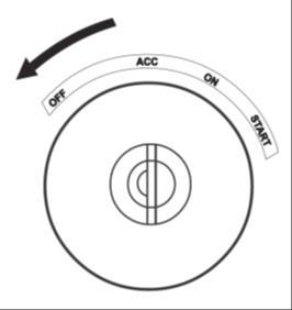
Release the key immediately after starting the engine. The starter switch returns to ON position automatically.
If the engine does not start, try to start the engine and start again.
If the engine does not start at all, check the electric system and contact HIDROMEK.
Important
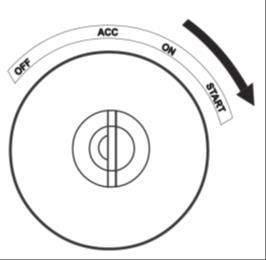
If the engine does not start even after the starter switch is turned to START position, return to STOP (OFF) position again. Do not hold the key in the START position for more than 20 seconds without an interruption, as this could seriously damage the starting system. In 2 minutes, try to start the engine again. If abnormal sounds, excessive vibration, or abnormal operation occurs, turn the key to STOP (OFF) position immediately to stop the engine.
After starting the engine, follow steps in “Warming Up”.
Caution
In cold season, immediately after the engine is started, the operating sound of the engine may be slightly louder than when it is warmed up and the smoke of the exhaust gas may slightly increase, but this is not abnormal. When the engine is not sufficiently warmed up, the engine oil is not supplied adequately, and a breakdown may result. Be practically careful in the cold season.
4.3. WARM-UP OPERATION
Caution
Avoid a quick increase of engine speed or load immediately after the engine is started. First, idle the engine for about 10 minutes, and then check the operating status of instruments and warning lights. Also, check for abnormal vibration from the engine, noise, and the conditions of smell and color in the exhaust gas.
4.3.1. AUTOMATIC WARM-UP OPERATION
If the hydraulic oil temperature and the engine coolant temperature are low, the control system will start automatic warm-up operation. This will be observed particularly in cold weather operations. Warm-up is necessary to prevent damage to the hydraulic system and the engine.
Proceed with the following steps for warming:
Important
If abnormal sounds, excessive vibration, or abnormal operation occurs, turn the key to OFF position immediately to stop the engine.
1. After starting the engine, “Engine Warm Up” message appears on MED to indicate that the engine cooling system and hydraulic system is warming-up. Message displays until the temperatures reach minimum required values.
2. While engine is automatically warming-up, the engine rpm is gradually increased to 1200 rpm and cannot exceed this value until the system is warm enough.
3. Engine warm-up operation may take up to 15 minutes depending on the external temperature.
4. In case it is necessary for emergency or maintenance needs, operator may cancel preheat function by pressing 3 seconds auto warm up stop switch to cancel pre-heat.
4.3.2. WARMING-UP HYDRAULICS
1. Lower the left control console to release the safety locking system,

2. Raise the bucket from the ground.
3. Slowly move attachments without a load for five minutes, swing clockwise / counterclockwise a few times, to circulate the oil through the system. Travel forward and reverse at low speed for about two revolutions of the drive sprocket.
4. If any abnormal operation such as delayed response occurs in any operation, warm up the hydraulics as described.
WARNING
The SAFETY LOCK LEVER must be pushed in LOCKED position to prevent machine controls from an accidental movement.
When the safety lock lever is at straight position, the safety locking system is UNLOCKED. Make sure to rotate safety lock lever down to correctly engage the LOCKED position.
See chapter 3.15. "SAFETY LOCKING DEVICE".
IMPORTANT
Never operate the control levers with higher stroke when the hydraulic oil temperature is low. Always perform the warm-up procedures to raise hydraulic oil temperature.
4.4. INSPECTIONS AFTER STARTING THE ENGINE
After warming up, check whether the gauges, warning lamps and pilot lamps are as in the following.
4.4.1. “ENGINE OIL PRESSURE IS LOW”
WARNING LAMP
Status: OFF
After the engine is warmed up, confirm that the engine oil low indicator is turned off.
CAUTION
Since the oil pressure is low immediately after the engine is started, take measurements after the engine is warmed up.
CAUTION
For the following cases, immediately stop the engine, check the oil level and inspect for an oil leakage: The oil pressure warning light flashes or comes on
When the oil level is normal and no oil leak is found, a failure in the hydraulic system can be suspected. Promptly consult a Hidromek Authorized Service
4.4.2. ENGINE WARNING LIGHT
Status: OFF
CAUTION
When the failure indicator light comes on, or the engine failure code is indicated in the liquid crystal display (LCD) on the actual machine, promptly contact a Hidromek Authorized Service.
4.4.3. BATTERY CHARGE WARNING LAMP
Status: OFF
CAUTION
Make sure to confirm that the alternator warning light turns off.
4.4.4. ENGINE TEMPERATURE GAUGE
Status: NORMAL
4.4.5. HYDRAULIC OIL TEMPERATURE GAUGE
Status: NORMAL
4.4.6. FUEL LEVEL GAUGE
Status: NORMAL
4.4.7. AIR CLEANER IS CLOGGED INDICATOR
Status: OFF
4.4.8. AUTO WARM UP INDICATOR
Status: OFF
4.4.9. DEF/AdBlue® INJECTION SYSTEM
WARNING LIGHT
Status: OFF
4.4.10. REDUCED ENGINE POWER INDICATOR
LIGHT
Status: OFF
4.4.11. PARKING INDICATOR
Status: OFF
4.4.12. LOW BRAKE PRESSURE
Status: OFF
4.4.14. ABNORMAL NOISE OF ENGINE AND COLOR OF EXHAUST SMOKE
CAUTION
Immediately after the engine is started, the engine sound is louder compared to the sound after the engine is warmed up, and also the color of the exhaust smoke becomes more whitened or more blackened than the smoke discharged during the normal operation. The engine sound and the color of the exhaust smoke turn to normal after the engine is warmed up.
During urea SCR system purging and its cancellation, the sound may change, but this does not indicate a failure.
If an abnormality is found in the engine sound or the color of the exhaust, immediately contact a Hidromek Authorized Service.
4.4.14.1. ABNORMAL NOISE OF ENGINE
Listen to the engine sound carefully, and if an abnormal noise is heard, check the engine and identify the possible cause.
4.4.14.2. COLOR OF EXHAUST SMOKE
Check the combustion state of the fuel and the urea SCR system condition by observing the color of the exhaust smoke.
After the engine is warmed up, the color of the exhaust smoke becomes as follows without any load applied.
Also, inspect the exhaust pipe for leakage.
CAUTION
During urea SCR system purging, white smoke may be emitted temporarily, but this is not a failure.
When the engine is started in a low temperature, moisture vapor may be generated temporarily, but this is not a failure.
4.4.15. BRAKE TEST
Perform brake test as told in the chapter 3.24.3
4.4.13. AXLE LOCK INDICATOR
Status: OFF
4.4.16. COOLANT TEMPERATURE
Both too high and too low temperatures of the coolant can cause an engine malfunction. The temperature in the range of approx. 75~90°C (167~194°F) is suitable.
When the engine coolant temperature gauge reads a value exceeding the appropriate temperature, or when the coolant temperature warning light comes on, a dangerous condition of substantially heated engine can be suspected.
When the temperature of the coolant exceeds the appropriate temperature, the fuel flow is restricted. After stopping the machine operation, decrease the engine speed to the level equal to the idling speed, and then confirm that the coolant temperature has dropped to the appropriate temperature before stopping the engine.
Caution
Avoid stopping the engine when it is overheated. Operating the engine for a long period of time with a low coolant temperature not only increases the oil and fuel consumptions but also accelerates the engine wear, resulting in an engine failure.
4.4.17. HOUR METER (CUMULATIVE OPERATING HOUR COUNTER)
The cumulative time during engine operation is counted. Confirm that it is always operating while driving. Perform inspection and maintenance on each part in accordance with the time count displayed in this hour meter.
CAUTION
The hour meter cannot be reset.
4.4.18. BE CAREFUL WITH THE TOO COLD ENGINE
When the engine is too cold, in addition to engine wear, it will also deteriorate fuel economy. While operating the machine, when the coolant temperature does not reach the appropriate temperature (approx. 75 - 90 °C (167 - 194 °F)) indefinitely, take an appropriate action such as inspecting or replacing the thermostat.
4.4.19. WHEN THE WARNING LIGHT COMES ON
4.4.20.
When The Engine Coolant Is Hot
Do not loosen or remove the radiator cap. Doing so would be dangerous because steam and hot air will spurt out.
Caution
It is dangerous to ignore the warning light and continue operating the machine. Perform an inspection and take appropriate actions. When the meter shows an abnormality, take necessary actions.
4.5. OPERATING THE MACHINE
4.5.1. FORWARD TRAVEL WARNING
Make sure to read and understand all operating controls, Cautions, and Warnings before traveling.
Obey all traffic rules and regulations. Do not travel faster than conditions allow.
Before putting the machine into gear, make sure in which direction the machine is facing. Locate the front section of the excavator and select the appropriate gear for the direction of travel desired.
Before moving, make sure that there are no personnel in the way or on the machine. Sound the horn to alert workers that you are above to move the machine.
Be sure the path is clear during travel, especially when traveling in reverse gear.
If an alarm buzzer sounds or a warning light turns “ON”, stop machine and determine the cause of the problem.
If an unusual sound or smell is noticed, immediately stop the machine and determine the cause of the problem. Avoid sudden stops or turns. The machine is top heavy. Make sure to make turns at a slow speed.
Take extreme caution when traveling on road shoulders or narrow streets.
Before leaving the operators seat, make sure to lock out all control systems and shut down the engine to avoid accidental activation.
4.5.2. BEFORE TRAVELING
1) Raise the outrigger and dozer blade and make safe.
2) Before putting the machine into gear, make sure in which direction the machine is facing. Locate the front section of the excavator and select the appropriate gear for the direction of travel desired
3) Before moving the excavator, make sure that the swing lock pin has been engaged. This will prevent the excavator from accidentally rotating during traveling.
4) Before traveling make sure that axle lock switch is set to the OFF position.
5) Set the mode selection switch in the “T”, travel position.


Warning
The SAFETY LOCK LEVER must be pulled in LOCKED position to prevent machine controls from an accidental movement. The operator must lock the safety lever before he leaves the operator’s seat and especially during maintenance and repair work unless it is necessary to operate the machine for this purpose. If not, an accidental movement of any control lever will cause the machine or an attachment to move, and will cause serious injury or death.
4.5.3. TRAVELING PROCEDURES
1. Make sure that “Brake System Failure Indicator Light”, buzzer and “Low Brake Pressure” message is off.
2. After making sure the front attachment is facing forward, set the mode selection switch in the “T”, travel position.

3. Using the FNR Switch, select forward or reverse travel direction and step on the accelerator pedal.
4. Test the brakes before beginning over the road travel.
5. During forward motion you can shift from speed range 1, to speed range 2 with using FNR Switch on the steering console. Downshifting from speed range 2 to speed range 1 should not be done if the machine is traveling at high rate of speed. Damage to the transmission could result.
6. To stop the machine, release slowly the accelerator pedal. The dynamic braking action of the machine’s momentum against the engine’s backpressure will begin to slow the machine. Step on the brake to bring the machine to stop.
Important
Never drive down a slope with speed range 2; otherwise dynamic braking action of the machine’s momentum will be insufficient. Drive down a slope with a speed range 1 and low speed traveling position. It can be impossible to stop the machine when brake failure is occur.
7. After traveling a long distance, front attachment, outriggers or dozer blade may begin to drift due to normal internal hydraulic leakage. Position the machine in a safe location and reposition the front attachment, outriggers or dozer blade.
4.5.4. PARKING PROCEDURE
1. Slowly release the pressure on the accelerator pedal.
2. Step on the brake to fully stop the machine.
3. Move the FNR Switch to the “N”, neutral position.
4. Reduce the engine speed to idle level from the instrument panel.
5. Lower the bucket and the dozer blade to the ground.
6. Pull the safety lock lever.
7. Move the mode selection switch to “P” park mode.
8. Shut the engine down.
9. If the machine is parked on a slope, insert the wheel chocks on the downhill side of the wheels to secure the machine.
NOTE:
As the brake pedal is applied and if it is pressed all the way to the floor, a mechanical lock will engage and hold the pedal in the fully applied position.
4.6. TRAVEL DIRECTION CONTROL
Caution
Before putting the machine into gear, make sure in which direction the machine is facing. Locate the front section of the excavator and select the appropriate gear for the direction of travel desired. Never change the travel direction rapidly.
4.6.1. STEERING
This machine can be turned by turning steering wheel to the desired direction.
4.7. SWINGING THE MACHINE
WARNING
Check for personnel or obstructions around the machine before swinging.
Operate the left control lever to swing.
4.6.2. DRIVING FORWARD AND REVERSE
DRIVING FORWARD
Push this lever forward (F direction) and machine will move forward.
NEUTRAL POSITION
Center position (N position) of this lever is neutral position.
DRIVING BACKWARD
Pull this lever to the backward (R direction) and machine will move backward.


