TMS800E OPERATOR’S MANUAL 6.
SET-UP AND INSTALLATION
Remove retainer clip (1, Figure 4-15) from the pin attaching the 7m (23 ft) section to the base section.
.
9.
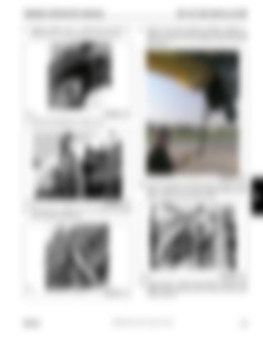
Remove the boom extension stowage controller (1, Figure 4-18) from behind the seat in the superstructure cab and connect it to the electrical plug (2) near the boom nose.
2
1
6642-5
7.
FIGURE 4-15
Remove the stowage pin (1,Figure 4-16).
1
FIGURE 4-18
10. Use the controller to pivot the boom extension so that lugs (1, Figure 4-19) on boom extension align with the holes in the lugs (2) on the boom nose. 1
6642-6
8.
FIGURE 4-16
Stow the pin (1, Figure 4-17) in pin holder (2) provided on the swingaway extension.
2
1
2
6642-11
6642-7
1
GROVE
FIGURE 4-17
FIGURE 4-19
11. Remove pins (1, Figure 4-20) stowed in extension and install in holes (right side of boom nose) and secure with retainer clips (2).
Published 09-14-2012, Control # 132-07
4-15
4


