4 minute read
TMS800E OPERATOR’S MANUALSET-UP AND INSTALLATION


• Use an auxiliary crane to couple the holding device to the connection eyes (3) on the auxiliary boom nose and lift it to the left onto the main boom head.
• Align the auxiliary single-sheave boom nose so that the bearing point (2) lines up to the front bore holes in the holding device.
Advertisement
• Secure the auxiliary single-sheave boom nose to the holding device using a pin (1).
• Secure the pin (1) with a retaining pin (4).
• Depending on the application, bring the auxiliary singlesheave boom nose into transport position or working position.
Removing the Auxiliary Single-Sheave Boom Nose
• Remove the retaining pins and draw all the pins out of the bores and bearing points.
• In the transport position, the auxiliary single-sheave boom nose is positioned to the side of the main boom head and is fastened with two pins.
• Lift the auxiliary single-sheave boom nose from the head of the main boom.
• Insert the two thin pins (1) and (3) into the bearing points (2) and (4) on the auxiliary single-sheave boom nose Figure4-70.
• Insert the two pins (5) into the mounting brackets (6) in front on the auxiliary single-sheave boom nose.
• Secure all pins using retainer pins.
RIGGING THE AUXILIARY SINGLE-SHEAVE BOOM NOSE
Rigging in Transport Position
• Attach an auxiliary crane to the connection eyes of the boom nose.
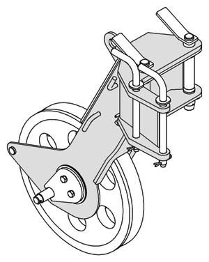
In the working position, the auxiliary single-sheave boom nose is positioned in front of the main boom head and is fastened with three pins (1) Figure4-69.
• Remove the retaining pins and draw all the pins out of the bores and bearing points.
In the transport position, the auxiliary single-sheave boom nose is positioned to the side of the main boom head and is fastened with two pins.
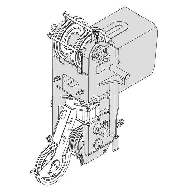
On the left side of the main boom head there is a holding device. In transport position, the boom nose is connected to the rear bore holes on the holding device Figure4-71.
Published 09-14-2012, Control # 132-07
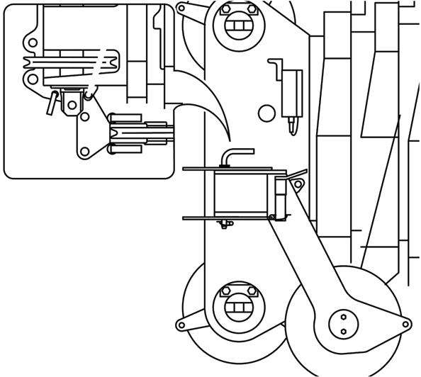
• Remove the retaining pins and take both pins (1) out of the bearing points (2) at the front of the main boom head Figure4-72.
• Insert both pins into the holders (3) and secure them with retaining pins.
• Release the retaining pin and remove the thin pin from the bearing point (4).
• Slew the auxiliary boom nose to the side of the main boom head.
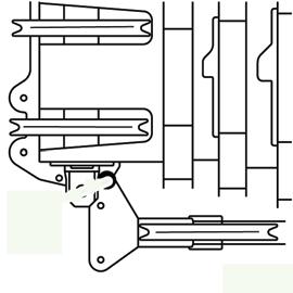
• Using the thin pin (1), fasten the auxiliary single-sheave boom nose to the bearing point (2) Figure4-73.
• Secure the pin with a retaining pin.
• The auxiliary single-sheave boom nose is now in transport position.
Rigging in Working Position
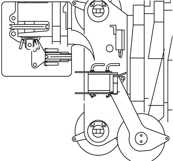
On the left side of the main boom head, there is a holding device. In working position, the auxiliary single-sheave boom nose is attached to the main boom head at both bore holes Figure4-74.
• Release the retaining pin and remove the thin pin from the bearing point Figure4-75.
• Swing the auxiliary single-sheave boom nose in front of the main boom head.
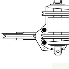
• Remove the retaining pin and take out both thick pins from the holders Figure4-76.
• Insert both pins into the pivot points at the front of the main boom head and secure them with retaining pins.
• Insert the thin pin into the bearing point and secure it with a retaining pin.
The auxiliary single-sheave boom nose is now in working position.
Attaching and Removing Hoist Cable
• When reeving, guide the hoist cable over the left hand upper sheave of the main boom.
• Insert the rope holding rod into the appropriate bore holes and secure them with the corresponding retaining pins.
• Fasten the cable end clamp on the hook tackle or the hook block.
Reverse the sequence of operations to remove the hoist cable before slewing the auxiliary boom nose into transport position.
Possible Reeving Methods on the Auxiliary Single-Sheave Boom Nose
NOTE: The hoist cable may only be simply reeved (single drop).
• maximum load bearing capacity:
• for single-reeving 16,000 lbs (7.3 t)
Lifting Limit Switch In Operation
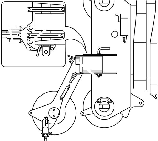
• Remove the cable holding rods from the head of the main boom and from the auxiliary single-sheave boom nose Figure4-77.
• Pull the plug of the connecting cable from the dummy socket (2) Figure4-78.
• Unwind the connecting cable from the holders (3).
• Insert the plug of the connecting cable into the socket (1) on the main boom head.
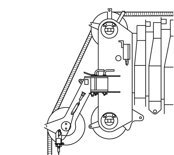
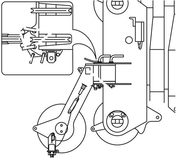
• Guide the hoist cable through the lifting limit switch weight.
Published 09-14-2012, Control # 132-07
During Transport
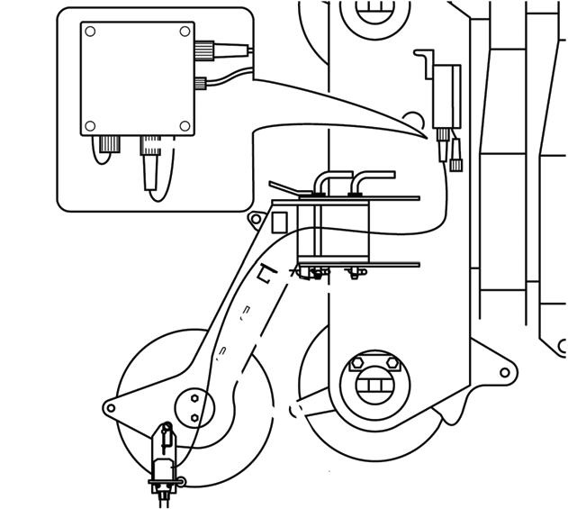
• Insert the plug of the connecting cable into the dummy socket (2) Figure4-79
• Wind the connecting cable onto the holders (3).
• Plug the short-circuit plug into the socket (1).
Telescoping With Rigged Lattice Extension
Caution
The main boom may become overloaded!
If you telescope the main boom with a rigged lattice extension or boom extension. You must not rotate the superstructure at the same time. This prevents the main boom being subjected to additional side forces and increased vibration and becoming overloaded.
NOTE: Do not actuate the slewing gear when telescoping.
Operating With The Lattice Extension
NOTE: The information in this section also applies to operation with the boom extension. Observe the following safety instruction before working with the boom extension.
Caution
Risk of overturning when working with the boom extension!
Raising And Setting Down The Main Boom With Rigged Lattice Extension
NOTE: The information in this section also applies for raising and setting down the main boom with a rigged boom extension.
To raise and lower the main boom with a rigged lattice extension, the main boom must be fully retracted.
For raising and lowering, the following prerequisites must be fulfilled:
- Apart from the hook block there is no load on the lattice extension.
When lifting over the swingaway and/or jib combinations, deduct the total weight of all load handling devices reeved over the main boom nose directly from the swingaway or jib capacity.
NOTE: The hoisting, lowering, swinging, lifting and telescoping movements are done in the same way as when operating with the main boom. Telescoping is permitted only at main boom angles of approximately 75° - 80°, depending on the length of the lattice extension.
Procedure if the Permissible Wind Speed is Exceeded
Strong winds can overstrain the crane. Therefore, closely observe the instructions in table.
If the maximum permissible wind speed according to the lifting capacity table is exceeded during the main boom operation, proceed per the following table (Table 4-2):
Published 09-14-2012, Control # 132-07