7 minute read
TMS800E OPERATOR’S MANUALSET-UP AND INSTALLATION


5. Extend boom approximately 60.9 cm (2 feet).
6. Raise boom above horizontal.
Advertisement
NOTE: Step 7 is stowing with the 7 m (23 ft) section and 10.1 m (33 ft) section together. If the 7 m (23 ft) section remained on the boom, proceed to step 9.
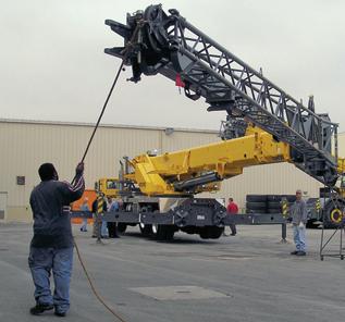
7. Use the tag line to maintain control of the boom extension, and swing the extension into the stowed position Figure4-46.
11. Lower the boom.
Danger
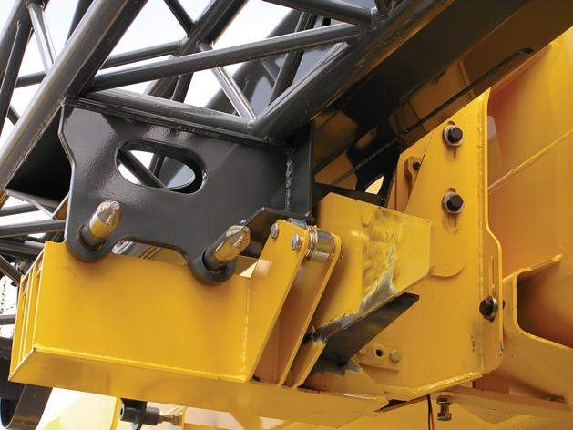
If the 33 ft lattice extension (1, Figure4-47) does not engage the ramp (2, Figure Figure4-47) correctly or does not align with the front stowage bracket (2, Figure4-48) correctly, STOP. DO NOT continue to stow the boom extensions until they are properly secured at these two points.
DO NOT climb onto decking or walk under boom extensions.
Sever injury or death may occur if the front stowage bracket and ramp are not properly attached to the boom extensions; the boom extensions may fall or swing away from the main boom stowage brackets.
Contact Manitowoc CraneCARE for correct adjustments if unable to align the lattice extension with the stowage brackets.
NOTE: Step 8 is with the 7 m (23 ft) section stowed on boom. If stowing the 7 m (23 ft) section and 10.1 m (33 ft) section together, proceed to step 10.
8. Use the tag line to maintain control of the boom extension Figure4-46, and swing the extension into stowed position until tag line can be attached to superstructure.
9. Raise the boom to ensure wear pad rests against bumper plate on ramp Figure 4-47.
10. Completely retract boom so that the boom extension (1, Figure4-47) stows on the ramp (2) and front stowage brackets.
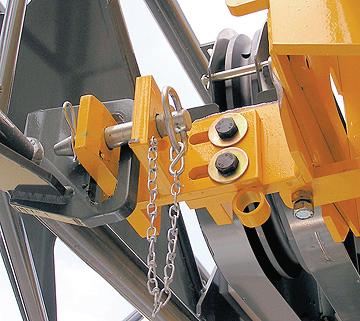
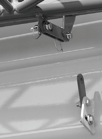
12. Remove the stowage pin from the holder at the front mount. Secure the lattice extension (1, Figure 4-48) to boom front stowage bracket (2) using stowage pin (3) and clip pin (4).
Danger
Never remove the stowage pins from the right side boom nose lugs (1, Figure4-49) until the 10.1 (33 ft) lattice extension has been properly secured to the stowage ramp (2, Figure4-47) and front stowage bracket (2, Figure 4-48).
Sever injury or death may occur, boom extensions will fall from the main boom if not secured properly.
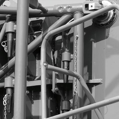
13. Remove pins from right side boom nose lugs (1, Figure4-49). Stow the pins in pin holders (2) on boom extension and install retainer clips.
Published 09-14-2012, Control # 132-07 a. If the 7 m (23 ft) was left stowed, use controller to pivot boom extension in towards boom so that the lugs on 10.1 m (33 ft) section align with 7 m (23 ft) section. b. If using both the 10.1 m (33 feet) and 7 m (23 ft) sections, use the controller to pivot boom extension towards boom such that the lugs on the 7 m (23 ft) section align with rear stowage bracket.
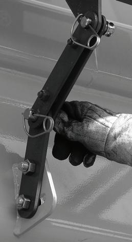
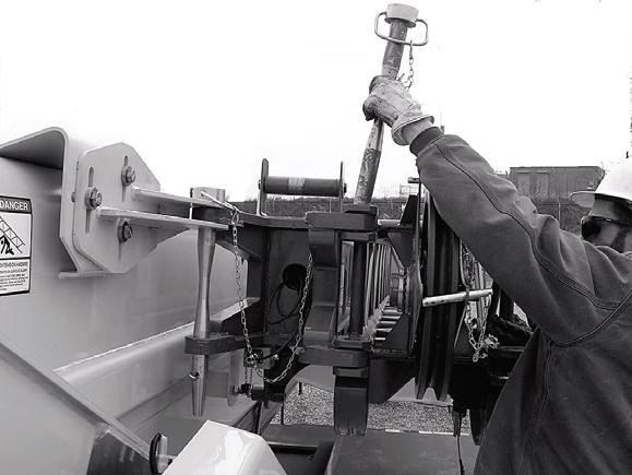
15. If the bi-fold 7m (23 ft) section was not used, remove bifold stowage pin (1, Figure4-51) from bi-fold and install at the lattice/bi-fold connection. Install retainer clip to pin.
NOTE: Perform steps 14 and 15 if stowing the 10.1 m (33 ft) section when the 7 m (23 ft) section remained on the boom, otherwise proceed to step 19.
14. If the bi-fold 7m (23 ft) section was not used, remove pin (1, Figure4-50, photo 6642-9) from the base section locking bar (2). Move locking bar (3, Figure4-50, photo 6642-8) to the 7 m (23 ft) section (4) and install pin (1). Secure with retaining pin.
NOTE: Step 16 applies when the 7m (23 ft) section was erected with the 10.1 m (33 ft) section.
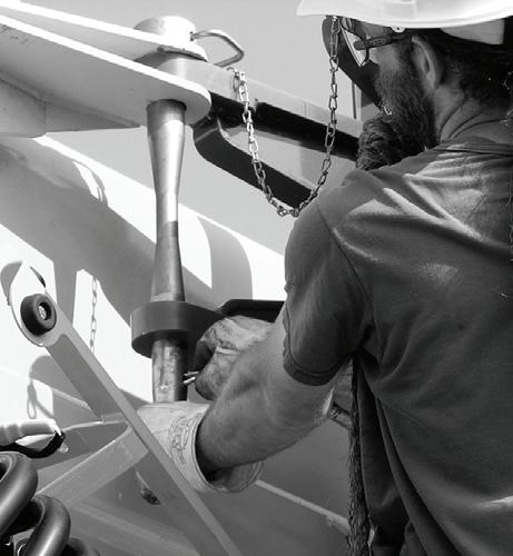
16. Install rear stowage pin (1, Figure4-52) and retainer clip (2).
17. Lower boom.
18. Remove tag line. Reeve the hoist cable as described in this section
Raising and Lowering the Hydraulic Boom Extension
NOTE: For more information on operation of the boom extension switches, refer to Section 3 - Operating Controls and Procedures.
When erecting
To remotely raise or lower the lattice extension when erecting there are two control units each with two push buttons on the 33 ft (10.1 m) section.
• Press the top push-button to raise the lattice extension (1).
• Press the bottom push-button to lower the lattice extension (2).
During operation
During operation the lattice extension is raised or lowered from the crane cab. The lattice extension can be raised or lowered, only when the power for the lattice extension is switched on.
When the power is switched on:
- The indicator lamp in the on/off rocker switch on the lattice extension lights up brightly.
- Activation of the power is shown on the RCL display.
• If necessary, switch on the power of the lattice extension, by pressing the lattice extension on/off rocker switch.
To raise, press the switch to the rear.
To lower, press the switch to the front.
Transportation on a Separate Vehicle
Danger
Risk of accidents from a falling lattice extension. Only attach the lattice extension in such a way that it is positioned in the center of gravity and always use lifting gear with sufficient lifting capacity. This prevents the lattice extension from fallin g and injuring people while loading.
• Check if all the required connections for transport condition are established.
• For transportation, place the lattice extension on the skid at the front and onto the lower cross strut at the rear of the 33 ft (10.1 m) section.
• Always secure the lattice extension on the separate vehicle with belts as well as to prevent slipping and overturning.
Caution
Risk of damaging the lattice extension. Always secure the lattice extension by tying it down with suitable belts when it is transported on the separate vehicle. This prevents the two-stage swingaway lattice extension tipping and becoming damaged during transportation.
Lifting Limit Switch on the Lattice Extension
The functions raise hoist, extend main boom and lower main boom are monitored during operation with the lattice extension by the lifting switch on the lattice extension and are switched off when the lifting limit switch is actuated.
NOTE: The same lifting limit switch is used for lattice extension and main boom.
Overriding Connection on Main Boom
For operation with the lattice extension you must remove the lifting limit switch on the main boom and override the connection.
• Insert the short-circuit plug (1) in the socket for the connection of the lifting limit switch Figure4-53. The connection is now overridden.
On 33 ft (10.1 m) swingaway lattice extension
• Attach the lifting limit switch (3) in the holder (4) and secure it with a retaining pin. Figure4-53
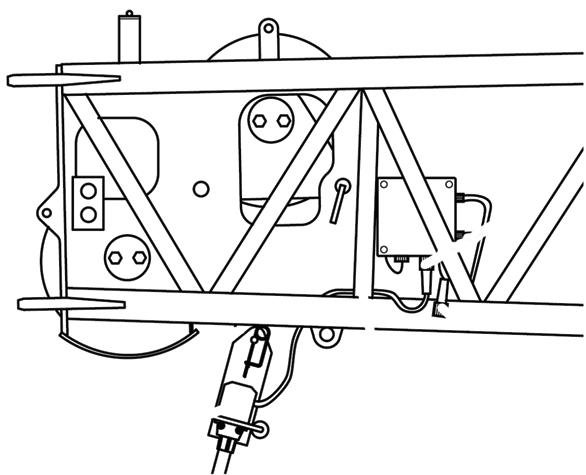
• Remove the short-circuit plug (2) from the socket (1).
• Connect the lifting limit switch on the socket (1).
• When unrigging you must insert the short-circuit plug (2) back in the socket (1).
Published 09-14-2012, Control # 132-07
On the 56 ft (17.1 m) Two-Stage Swingaway Lattice Extension
On the 33 ft (10.1 m) section, there is a deflection sheave at the rear (1) Figure4-55. Fold out the deflection sheave if the boom extension offset angle is 20° or 40°.
NOTE: For zero (0) degree offset, leave the mast assembly in the stowed position.
The sheave must be folded out:
• for operation with the swingaway lattice extension,
• for operation with the 56 ft (17.1 m) two-stage swingaway lattice extension.
For transportation the mast sheave must be folded in.
Folding Rear Deflection Sheave
Danger
w1525a FIGURE4-54
NOTE: For operation with the 56 ft (17.1 m) two-stage swingaway lattice extension the connection for the lifting limit switch on the 33 ft (10.1 m) section must be overridden with a short-circuit plug.
• Attach the lifting limit switch (2) on the shackle (1) and secure it with a retaining pin Figure4-54.
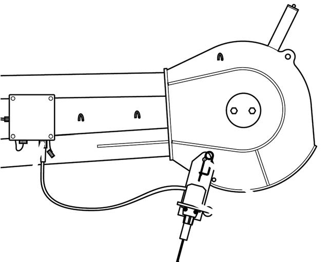
• Connect the lifting limit switch on the socket (3).
• When stowing, close the socket (3) with the protective cap.
Folding Out/In the Deflection Sheaves on the 33 ft (10.1 m) Section
Risk of crushing.
Always hold the deflection sheave by the handle, when removing the pin. You might get your fingers crushed if you hold the sheave by the side plates.
Folding Out Deflection Sheave
To prevent the hoist rope dragging on the main boom or lattice extension during operation with the lattice extension or boom extension, the hoist rope is guided via deflection sheaves.
• Remove the pin (2) from the bore (1).Figure4-56
• Fold the deflection sheave up and secure it with the pin in the bore (3).
• Secure the pin with a retaining pin.
Folding In Deflection Sheave
• Remove the pin (2) from the bore (3).
• Fold the deflection sheave down and insert the pin in the bore (1).
• Secure the pin with a retaining pin.
Positioning/Remove the Hoist Cable
Danger
Risk of accidents due to falling parts. Always secure the hoist cable holding rollers and rods with retaining pin. This prevents elements from coming loose, falling down and injuring people.
Positioning Hoist Cable
• Remove the hoist cable holding rollers and rod (1) Figure4-57.
• Guide the hoist rope via the deflection sheaves (3) and via the head sheave (2) on the 33 ft (10.1 m) section or on the 23 ft (7 m) section. Put all hoist cable holding rollers and rods back in place and secure these with retaining pins.
• Attach the overhaul ball.
• Install the A2B weight assembly.
Removing Hoist Cable
• Unpin the overhaul ball.
• Remove the hoist cable holding rollers and rods (1).
• Take the hoist cable off the head sheave (2) and the deflection sheaves (3) and place it onto the ground on the left side.
Setting the Folding Swingaway Extension Offset
Danger
Ensure any blocking material used is adequate to support the weight of the extension assembly without tipping or falling.
1. Extend and set the outriggers and swing the boom to over the front. Position the boom to above horizontal.
Figure4-58
2. Block up under the tip of the extension assembly section.
3. To set the offset from a lesser degree to higher degree, perform the following procedures.
Caution
Do not overload the extension anchor fittings or the extension base section when lowering the boom. FIGURE4-57
Published 09-14-2012, Control # 132-07 a. Slowly lower the boom until the pressure is relieved on the offset link pins. b. Remove the offset link clip pins and attach pins securing the offset links in the lesser degree offset position. If going to maximum offset, stow them in the stowage lugs. If going to the intermediate (20 degree) offset, install them in the offset links for that degree of offset. c. Slowly elevate and telescope the boom at the same time so that the extension does not move off of the blocking until the offset links take the full weight of the extension. d. Reeve the hoist cable as described under normal erecting procedures.
To obtain maximum degree offset, remove pin and stow in lug.
NOTE: For 20 or 40 degree offset, make sure the mast is in the raised position.
REMOVING THE BI-FOLD MANUAL BOOM EXTENSION
Danger
To prevent serious injury or death, always wear personal protective equipment; i.e., a hard hat, eye protection, gloves and metatarsal boots.
1. Before removing the boom extension make sure the crane is set up on outriggers using normal setup procedures. Refer to Section 3 - OPERATING CONTROLS and PROCEDURES.
NOTE: An auxiliary crane with sling is required to remove the bi-fold boom extension.