6 minute read
TMS800E OPERATOR’S MANUALSET-UP AND INSTALLATION


General
This section provides procedures for installing the hoist cable on the hoist drum, cable reeving, and erecting and stowing the boom extension.
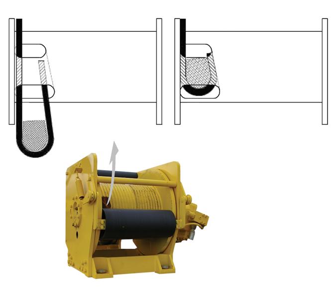
INSTALLING CABLE ON THE HOIST
Caution
If cable is wound from the storage drum, the reel should be rotated in the same direction as the hoist.
NOTE: The cable should preferably be straightened before installation on the hoist drum.
Install cable on the hoist drum in accordance with the following procedure.
1. Position the cable over the boom nose sheave and route to the hoist drum.
2. Position the hoist drum with the cable anchor slot on top.
3. Insert the cable through the slot and position around the anchor wedge (1) Figure4-1.
NOTE: The end of the cable should be even with the bottom of the slot for the anchor wedge.
line pull, multi-part lines allow the operator to raise a greater load than can be raised with a single part line. Various cable reeving (part line) is possible with the boom nose and hook block Figure 4-6 and Figure 4-7. This reeving should be accomplished by a qualified rigger using standard rigging procedures.
Caution
Do not reeve Auxiliary Hoist rope through the rope grab. Do reeve the Main Hoist rope through the rope grab. If both Main & Auxiliary Hoists are being reeved, neither one may be reeved trough the rope grab. Keep it in the down position. Figure 4-2
4. Position the anchor wedge in the drum slot; pull firmly on the free end (2) of the cable to secure the wedge.
NOTE: If the wedge does not seat securely in the slot, carefully tap (3) the top of the wedge with a mallet.
NOTE: Also use the rope grab when using the Main Hoist with lattice extensions. To quick reeve the hook block without removing the wedge socket on the end of the cable refer to Figure 4-3.
5. Slowly rotate the drum, ensuring the first layer of cable is evenly wound onto the drum.
6. Install the remainder of the cable, as applicable.
Cable Reeving
NOTE: There are two types of cable (wire rope) available on this crane; 6 x 36 WS and 35 x 7 (non-rotating).
Within the limits of the load and range charts and permissible
DEAD-END RIGGING/WEDGE SOCKETS
Wedge socket assemblies are popular rigging accessories and have been successfully used for decades to terminate wire ropes on mobile cranes. A wedge socket assembly is easily installed and dismantled but it must be installed and used correctly. It is essential to use only a wedge and socket of the correct size for the rope fitted. Failure to do so may result in the rope pulling through the fitting.
Since state and local laws may vary, alternate attachment methods may be necessary depending upon work conditions. If alternate methods are selected, the user is responsible and should proceed in compliance with the regulations in force. If there are any questions, contact your local Grove Distributor or Manitowoc Crane Care.
Do not mix components from different manufacturers. The selection, installation and use of a wedge socket assembly must be in accordance with the requirements of the wedge socket manufacturer and the wire rope manufacturer upon whose wire rope the wedge socket assembly will be used.
Manitowoc/Grove Crane specifies the size, type, class and line pulls for wire rope, predominately rotation resistant wire rope, and rigging accessories such as overhaul balls and hook blocks for use with each new crane that it manufactures. Other wire ropes and rigging accessories are available from various vendors. Different wire rope manufacturers have differing requirements for the construction, handling, cutting, seizing, installation, termination, inspection and replacement of the wire ropes they produce. Their advice should be sought for each specific type of wire rope a crane user intends to install on a mobile crane.
When assembly is complete, raise the boom to a working position with a load suspended to firmly seat the wedge and rope into the socket before the crane is used operationally.
Caution
If the socket is not positioned with the flat face away from the boom sections, structural damage will occur.
When anchoring the socket to the boom, ensure the flat face of the socket is in position, as shown, away from the boom sections Figure 4-4.
Wedge Socket Installation
1. Inspect the wedge and socket. Remove any rough edges and burrs.
2. The end of the wire rope should be seized using soft, or annealed wire or strand. If the end of the rope is welded, the welded end should be cut off. Do not weld on size 6X37 rope. This will allow the distortion of the rope strands, caused by the bend around the wedge, to adjust themselves at the end of the line. Refer to SECTION 1 - INTRODUCTION in the Service Manual for wire rope procedures.
3. Make sure the live-end (Figure4-5) of the rope is directly in line with the ears of the socket and the direction of pull to which the rope will be subjected. If the rope is loaded into the socket incorrectly, under a load the rope will bend as it leaves the socket, and the edge of the socket will wear into the rope causing damage to the rope and eventual failure.
4. Insert the end of the wire rope into the socket, form a loop in the rope, and route the rope back through the socket allowing the dead-end (Figure4-5) to protrude from the socket. Ensure the dead-end of the rope is of
Published 09-14-2012, Control # 132-07 sufficient length to apply end treatment to the dead-end after the wedge has been seated.
5. Insert the wedge into the loop and pull the live-end of the rope until the wedge and rope are snug inside the socket. It is recommended that the wedge be seated inside the socket to properly secure the wire rope by using the crane’s hoist to first apply a light load to the live-end.
6. After final pin connections are made, increase the loads gradually until the wedge is properly seated.
7. The wire rope and wedge must be properly secured inside the socket before placing the crane into lifting service. It is the wedge that secures the wire rope inside the socket. The dead-end treatment is used to restrain the wedge from becoming dislodged from the socket should the rope suddenly become unloaded due to the headache ball or hook block striking the ground, etc; refer to “Dead-end Rigging” on page 2-4.
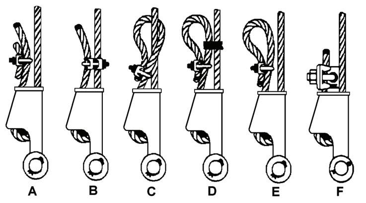
Dead-end Rigging
Sketches A through F (Figure4-6) illustrate various ANSI approved methods for treating the dead-ends of wire ropes which exit a wedge socket assembly. While use of the loopback method is acceptable, care must be exercised to avoid the loop becoming entangled with tree branches and other components during crane transport and with the anti-two block system and other components during use of the crane.
Of the methods shown below, Manitowoc prefers that method A or F be used, i.e., clipping a short piece of wire rope to the dead-end or using a commercially available specialty wedge. Typically, it is recommended that the tail length of the dead-end should be a minimum of 6 rope diameters but not less that 6in (15.2cm) for standard 6 to 8 strand ropes and 20 rope diameters but not less than 6in (15.2cm) for rotation resistant wire ropes.
When using method A, place a wire rope clip around the dead end by clamping a short extra piece of rope to the rope dead end. DO NOT CLAMP THE LIVE END. The U-bolt should bear against the dead end. The saddle of the clip should bear against the short extra piece. Torque the U-bolts according to the table titled Wire Rope Clip Torque Values (Table 4-1).
Other sources for information with which crane users should be familiar and follow is provided by the American Society of Mechanical Engineers, American National Standard, ASME B30.5, latest revised. ASME (formerly ANSI) B30.5 applies to cableways, cranes, derricks, hoists, hooks, jacks, and slings. It states, in section 5-1.7.3 , “(c) Swaged, compressed, or wedge socket fittings shall be applied as recommended by the rope, crane or fitting manufacturer.” Wire ropes are addressed in ASME B30.5, section 5-1.7.2, ROPES, it states, in pertinent part, “(a) The ropes shall be of a construction recommended by the rope or crane manufacturer, or person qualified for that service.” Additional information is published by the Wire Rope Technical Board in the Wire Rope Users Manual, latest revised edition.
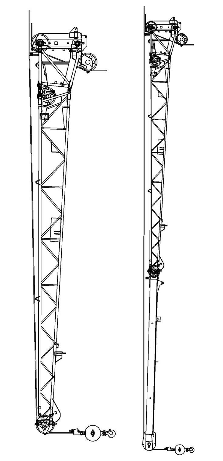
Upper Boom Nose Sheaves
9 PARTS LINE
To Main Hoist
Published 09-14-2012, Control # 132-07
Lower Boom Nose Sheaves